1. Introduction
Transfer zones are integral components of continental rifts, connecting basin boundary faults and transferring the throw from one fault to the other (Gibbs, Reference Gibbs1984; Gomes et al. Reference Gomes, Fossen, Almeida and Salmoni2018). Transfer zones are regarded as transversely oriented to moderately oblique fault zones with strike-slip motion in some literature (Gibbs, Reference Gibbs1984; Faulds & Varga, Reference Faulds and Varga1998). Several geometrically different types of transfer zones have been described in previous studies (Gibbs, Reference Gibbs1984; Morley et al. Reference Morley, Nelson, Patton and Munn1990; Gawthorpe & Hurst, Reference Gawthorpe and Hurst1993; Faulds & Varga, Reference Faulds and Varga1998), and the conjugate overlapping transfer zone (Morley et al. Reference Morley, Nelson, Patton and Munn1990) which forms between two oppositely dipping master faults is common in rift basins.
Previous studies of transfer zones in extensional basins have generally highlighted the geometrical structure and influence on sedimentation under a simple extensional background (Morley et al. Reference Morley, Nelson, Patton and Munn1990; Gawthorpe & Hurst, Reference Gawthorpe and Hurst1993; Moustafa, Reference Moustafa2002; Younes & McClay, Reference Younes and McClay2002; Wang et al. Reference Wang, Lu, Fu, Sun, Wang and Li2013; Moustafa & Khalil, Reference Moustafa and Khalil2017). However, many rift basins are documented to have developed through multiphase extension, possibly also with a different extension direction during each rift phase (Morley et al. Reference Morley, Haranya, Phoosongsee, Pongwapee, Kornsawan and Wonganan2004; Nixon et al. Reference Nixon, Sanderson, Dee, Bull, Humphreys and Swanson2014; Whipp et al. Reference Whipp, Jackson, Gawthorpe, Dreyer and Quinn2014; Duffy et al. Reference Duffy, Bell, Jackson, Gawthorpe and Whipp2015). These basins are commonly characterized by different fault orientations, fault styles and basin architectures, as observed in natural examples (Frankowicz & McClay, Reference Frankowicz and McClay2010; Nixon et al. Reference Nixon, Sanderson, Dee, Bull, Humphreys and Swanson2014; Whipp et al. Reference Whipp, Jackson, Gawthorpe, Dreyer and Quinn2014; Duffy et al. Reference Duffy, Bell, Jackson, Gawthorpe and Whipp2015) and physical models (Bonini et al. Reference Bonini, Souriot, Boccaletti and Brun1997; Keep & McClay, Reference Keep and McClay1997; Bellahsen & Daniel, Reference Bellahsen and Daniel2005; Henza et al. Reference Henza, Withjack and Schlische2010, Reference Henza, Withjack and Schlische2011). It is reasonable to assume that a later transfer zone is either inherited from an early transfer zone or is newly formed between later normal faults. In this study we consider a key area in the Bohai Bay Basin (BBB) in order to define the development and evolutionary stages of transfer zones under a two-phase rift, and to clarify the influence of these transfer zones on sedimentation patterns.
The BBB is one of the most petroliferous basins in northern China, and can be divided into several sags and uplifts (Fig. 1a, b). The sags are generally bounded by normal faults on one or several sides (Fig. 1b, c). At several locations, transfer zones result from the interference between the normal faults, and are preferred sites for hydrocarbon accumulation (Qi, Reference Qi2007; Yang, Reference Yang2009). The BBB underwent multiphase rifting stages during Palaeogene time, and fault geometries and displacement patterns significantly changed between the Eocene and Oligocene phases (Qi et al. Reference Qi, Zhang, Lu and Yang1995; Dai et al. Reference Dai, Lu, Qi and Chen1998; Qi, Reference Qi2004; Liang et al. Reference Liang, Wang, Bai, Ji and Duo2016). However, little is known about the development and evolutionary stages of transfer zones during multiphase rifting in the BBB.

Fig. 1. Simplified structural map illustrating the regional setting of the Baxian Sag. (a) Regional tectonic framework and location of the Bohai Bay Basin (BBB) (modified from Suo et al. Reference Suo, Li, Yu, Somerville, Liu, Zhao and Dai2014). (b) Tectonic map showing the Cenozoic subdivision of the BBB, including depressions and uplifts (modified from Qi & Yang, Reference Qi and Yang2010). The study area is bounded by a green rectangle, including the Baxian Sag, SE Langgu Sag, northern Niutuozhen uplift, and northern Raoyang Sag. JZD – Jizhong Depression. (c) The Cenozoic subdivision of the Jizhong Depression, including sags, uplifts and major faults (modified from Zhang et al. Reference Zhang, Yang, Chen, Qian, Zhang and Liu2008; Min et al. Reference Min, Xin, Zhang, Lv and Li2015). BXS – Baxian Sag; CXU – Cangxian Uplift; DCU – Dacheng Uplift; DXU – Daxing Uplift; LGS – Langgu Sag; NTZU – Niutuozhen Uplift; RYS – Raoyang Sag; WQS – Wuqing Sag.
The Baxian and Raoyang sags lie onshore in the BBB, and show an along-strike change in half-graben polarity (Figs 1c, 2). The study area consists of the Baxian Sag and northern Raoyang Sag, which is bounded by an S-type boundary faults (Wu, Reference Wu1986; Yang et al. Reference Yang, Liu, Sun and Cui2002a–c), consisting of the Niudong and Maxi faults (Figs 1c, 2). Several conclusions have been proposed within oil company reports. (1) Yang et al. (Reference Yang, Liu, Sun and Cui2002a, c) initially identified the NW–SE-trending transfer zone between the Baxian and Raoyang sags, and discussed the influences on the Palaeogene extensional deformation. (2) Xie & Deng (Reference Xie and Deng2008) and Lao et al. (Reference Lao, Wu and Chen2010, Reference Lao, Wu, Chen and Wu2012) further discussed the effects of this transfer zone on sedimentary facies and hydrocarbon accumulation. However, several important questions remain. How did the transfer zones form and evolve in time and space during multiphase rifting during Palaeogene time? The internal structural styles and architecture of the transfer zones, as well as their control on sediments, are still poorly known. In addition, an understanding of the close relationship between the transfer zone geometries, internal architecture and sediment distribution is crucial in hydrocarbon exploration. In this study, we consider two key syn-rift sequences and stratigraphic surface to define the positions, architectures and deformation styles of the transfer zones during the two-phase rift, and to clarify the impact of these zones on syn-rift sedimentation. This study also aims to address the significance of the transfer zones in terms of hydrocarbon exploration.
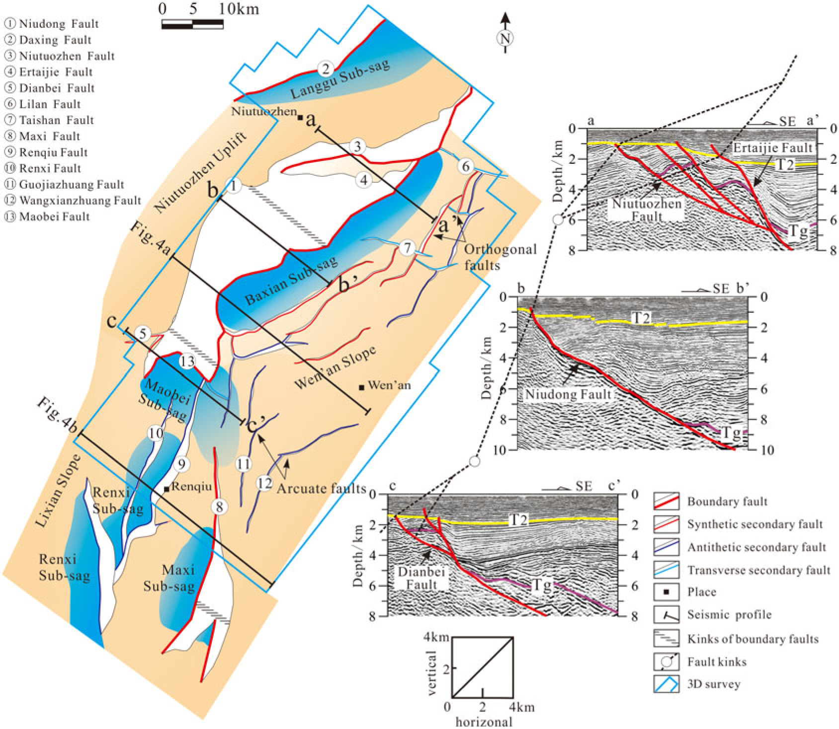
Fig. 2. Simplified structural map of the Baxian Sag and its adjacent areas showing the main faults and the main structural units (based on the top basement; refer to the pre-Cenozoic). The major depositional units are blue (the Langgu, Baxian, Maobei, Renxi and Maxi sub-sags); other units include the Niutuozhen Uplift and Wen’an Slope. The white areas on the structural map represent the fault planes. The Niudong Fault can be divided into three segments according to the strike; the north mainly includes Niutuozhen and Ertaijie faults, and the south is also known as the Dianbei Fault. Three seismic profiles (a–a’, b–b’, c–c’) are included to illustrate the geometry of different segments of the Niudong Fault. The Maxi Fault can be divided into the north and south segments according to the fault kink. T2 – the bottom reflection layer of the Neogene stratigraphy; Tg – the bottom reflection layer of the Palaeogene stratigraphy.
2. Geological setting
2.a. Structural geometries of the Baxian Sag
The study area consists of the Baxian Sag and northern part of Raoyang Sag, located in the middle of the eastern part of Jizhong Depression (one of the depressions in the BBB, including several sags and small-scale uplifts; Fig. 1c) and onshore part of the NW BBB (Fig. 1b, c). The structural framework of the Jizhong Depression is characterized by NE–SW-trending linear basement highs covered with Neogene or only a thin layer of Palaeogene sediments and bounded by normal faults (Zhao & Windley, Reference Zhao and Windley1990; Qi & Yang, Reference Qi and Yang2010; Fig. 1c). The Baxian Sag is bounded by the Niutuozhen Uplift to the west and the Dacheng Uplift to the east, while the southern and northern margins are connected to the Raoyang and Wuqing sags, respectively (Figs 1c, 2).
Petroleum exploration data confirm that regional normal faults form the sag boundaries (Qi, Reference Qi2007), namely the bounding faults. Two major bounding faults in the study area include the Niudong and Maxi faults, bounding the Baxian Sag and Maxi Sub-sag, respectively (Figs 1c, 2). The Niudong boundary fault is a growth fault that changes its orientation along-strike from ENE–WSW-trending in the north to NNE–SSW-trending in the south, while the Maxi Fault trends N–S along its northern end and changes into a more NNE–SSW trend southwards. Although these two major bounding faults do not link up, the two faults together form an S-shape in plan view (Fig. 2). Along the axis of the Baxian–Raoyang extensional province, the geometry of bounding faults and structural styles of half-grabens varies. The chain of the two half-grabens is separated by transverse faulted structural zone, also known as the transfer zone (Morley et al. Reference Morley, Nelson, Patton and Munn1990; Gawthorpe & Hurst, Reference Gawthorpe and Hurst1993; Yang et al. Reference Yang, Liu, Sun and Cui2002a, c; Xie & Deng, Reference Xie and Deng2008; Lao et al. Reference Lao, Wu, Chen and Wu2012). The Niudong Fault dips overall to the east while the Maxi Fault has the opposite polarity, and the two faults form an S-type fault system in the Baxian–Raoyang extensional province (Wu, Reference Wu1986; Yang et al. Reference Yang, Liu, Sun and Cui2002a, c; Figs 1c, 2). The major faults form the Cenozoic half-graben sags in the study area (Figs 3, 4). The Niudong Fault, controlling the formation of the Baxian Sag, developed in the west with hanging-wall block tapering to the east (Fig. 4a); the Raoyang Sag demonstrates the reverse (Fig. 4b).

Fig. 3. Stratigraphy and depositional environments in the Baxian Sag (modified from Zhao et al. Reference Zhao, Liu, Jin, Jin and Zhang2015). Ek – Kongdian Formation; Es – Shahejie Formation; Ed – Dongying Formation; Ng – Guantao Formation; Nm – Minghuazhen Formation; Qp – Pingyuan Formation; Mz – Mesozoic; Pz – Palaeozoic.
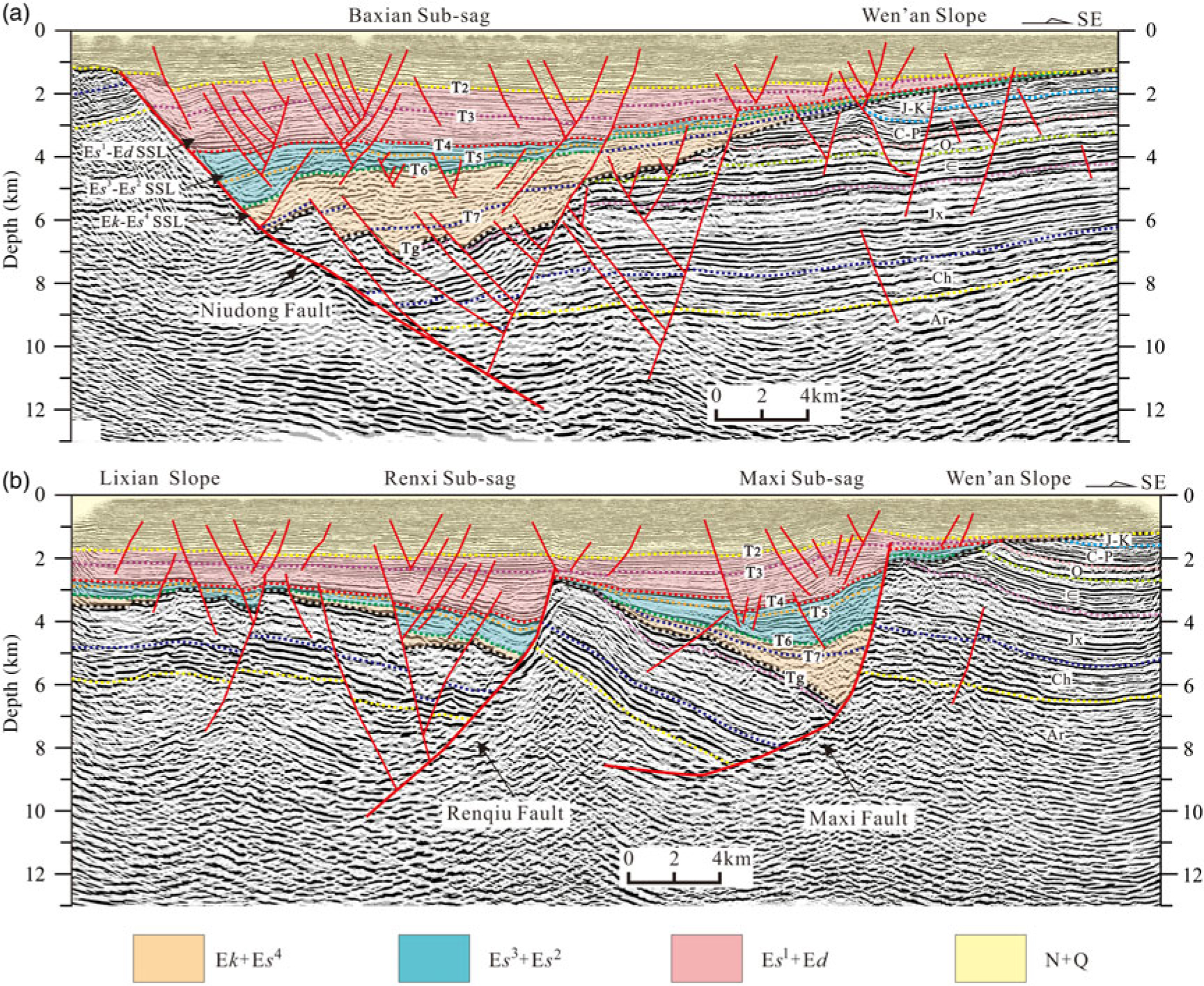
Fig. 4. Geoseismic sections illustrating the basin architecture and fault system across the (a) Baxian Sag and (b) Raoyang Sag. Locations are shown in Figure 2. Ar – Archaeozoic; C-P – Carboniferous and Permian; Ch – Changcheng of Proterozoic; J-K – Jurassic and Cretaceous; Jx – Jixian of Proterozoic; N+Q – Neogene and Quaternary; O – Ordovician; SSL – substructural layer; ∈ – Cambrian.
2.b. Structural-stratigraphic evolution of the Baxian Sag
The Baxian Sag is a NE–SW-trending asymmetrical half-graben (Fig. 2), and one of the most important oil- and gas-bearing areas in the BBB (Xie & Deng, Reference Xie and Deng2008; Zhao et al. Reference Zhao, Zhao, Liu, Wang and Ren2009; Feng et al. Reference Feng, Zhou, Ren, Zhen and Miao2010; Lu et al. Reference Lu, Liu, Wang, Zhang and Lian2010; Min et al. Reference Min, Xin, Zhang, Lv and Li2015). Petroleum exploration data have revealed that the basin sequences contain several unconformities (Figs 3, 4). There are two major regional unconformities: an angular unconformity between the Palaeogene and pre-Cenozoic stratigraphy (Tg in Fig. 4), representing an important tectonic event that marked the beginning of the rifting stage (Figs 3, 4); and an angular unconformity between the Neogene and Palaeogene stratigraphy (T2 in Fig. 4), marking the termination of the rifting stage and the onset of the post-rifting stage (Qi et al. Reference Qi, Zhang, Lu and Yang1995; Qi & Yang, Reference Qi and Yang2010; Figs 3, 4). Three tectono-stratigraphic levels have been divided according to the two major regional unconformities, which are (from bottom to top): the pre-Cenozoic basement, the Palaeogene syn-rift sequences, and the Neogene–Quaternary post-rift sequences (Figs 3, 4). The Palaeogene syn-rift sequences can be further subdivided into three substructural layers (SSLs) that represent the three syn-rift stages (Figs 3, 4).
The structural-stratigraphic evolution of Baxian Sag as summarized by previous studies is as follows (Dai et al. Reference Dai, Lu, Qi and Chen1998; Min et al. Reference Min, Xin, Zhang, Lv and Li2015; Chen et al. Reference Chen, Hao, Guo, Yin, Cao and Zou2018) (Fig. 3). (1) The pre-Cenozoic basement lay at the E-dipping limb of an ancient anticline formed before Cenozoic rifting, which consisted of Mesozoic, Permian, Carboniferous and Cambrian sedimentary and crystalline-metamorphic rocks (Zhao et al. Reference Zhao, Liu, Jin, Jin and Zhang2015). (2) The first rift stage (rifting I) initiated during late Palaeocene time and ceased during middle Eocene time, which corresponds to the deposition of the Kongdian Formation (Ek in Fig. 3) and the fourth member of the Shahejie Formation (Es 4 in Fig. 3). Basin deposition began with initially localized lacustrine and alluvial deposition during late Palaeogene – early Eocene time. Delta and lacustrine were then subsequently deposited. (3) The second rift stage (rifting II) initiated during middle–late Eocene time, and the third (Es 3) to second (Es 2) members of the Shahejie Formation, wide lacustrine and delta sediments, were deposited during this phase. (4) The third rift stage (rifting III) initiated at the beginning of Oligocene Epoch and resulted in the deposition of the first member of the Shahejie Formation (Es 1) and Dongying Formation (Ed). The sedimentary facies changed from delta and lacustrine to fluvial deposits. (5) The post-rifting thermal subsidence resulted in the deposition of Guantao (Ng), Minghuazhen (Nm) and Pingyuan (Qp) formations, which are mainly composed of fluvial deposits.
The BBB underwent three rift stages during the Palaeogene Period; the deformation styles, stratigraphic structures and fault systems of the first two stages are similar but those of the third stages are quite different (Qi & Yang, Reference Qi and Yang2010; Tong et al. Reference Tong, Zhao, Cao, Liu, Xiaomei and Zhao2013; Liang et al. Reference Liang, Yu, Liu, Wang, Li and Ma2014; Chen et al. Reference Chen, Ren, Xin, Zhang and Wu2015). In other words, there are two relatively independent structural deformation systems among the Palaeogene sequences in the BBB: the Eocene and Oligocene structural deformation systems (Qi & Yang, Reference Qi and Yang2010; Tong et al. Reference Tong, Zhao, Cao, Liu, Xiaomei and Zhao2013). The fault features and structural frameworks of the Eocene and Oligocene sequences are different (Huang et al. Reference Huang, Liu, Zhou and Wang2012a, Reference Huang, Wang and Wub, 2015; Tong et al. Reference Tong, Zhao, Cao, Liu, Xiaomei and Zhao2013; Liang et al. Reference Liang, Yu, Liu, Wang, Li and Ma2014; Chen et al. Reference Chen, Ren, Xin, Zhang and Wu2015; Zhang et al. Reference Zhang, Wu, Zhou, Niu, Li, Ren and Zhang2017). We therefore combine the first two stages and roughly divide the Palaeogene rift stages into two phases (Eocene and Oligocene). The two-phase transfer zones are recognized in the Eocene and Oligocene fault systems accordingly. Here we compile several structural maps and isopach maps to describe the differences between the two deformation systems and the development of two-phase transfer zones.
2.c. Fault systems in the Baxian Sag
Extensional fault systems are typical structural elements in the study area, and the faults predominantly trend NNE, NE, ENE and NW with their attitudes varying in different tectonic settings (Fig. 2). NE–SW- and ENE–WSW-striking faults prevail and NW–SE-striking faults are scarce. Previous studies on the properties of faults suggest that most faults are normal with only a few strike-slip faults (Zhang & Su, Reference Zhang and Su1999; Qi & Yang, Reference Qi and Yang2010).
The Niudong Fault changes its orientation along-strike from ENE–WSW-trending in the north to NNE–SSW-trending in the south in plan view, and shows a listric (concave) fault in section view (Figs 2, 4). According to the differences in strike direction and geometries, the Niudong Fault can be divided into three segments: north, central and south (Fig. 2). The north segments consist of a series of NE–ENE-striking and SE–ESE-dipping faults in a terrace zone, which are bounded by the Niutuozhen and Ertaijie faults (section a–a’ in Fig. 2). The central segment presents as a NNE–striking single fault (section b–b’ in Fig. 2), and the south segment consists of several secondary NE–ENE-striking faults (section c–c’ in Fig. 2). However, the Maxi Fault is a N–S- to NE–SW-striking bounding fault with opposing dip in the Raoyang Sag (Fig. 2). The Maxi Fault can be divided into northern and southern segments separated by the fault kink (Fig. 2).
In rift basins, it is logical to assume that major bounding faults, synthetic or antithetic secondary faults and transverse faults may be rigidly or softly linked with, or terminated by, detachment faults (Gibbs, Reference Gibbs1990). The linked extensional fault systems play an important role in controlling deposition of syn-rift sequences (Dawers & Underhill, Reference Dawers and Underhill2000). There are major secondary faults with different strikes in this region, such as the Lilan, Taishan and Renqiu faults (Fig. 2). These faults are closely related to the Niudong and Maxi faults. The Niudong Fault and these major secondary faults form an extensional fault system, which controls the structural framework and sediment deposition. The geometries of the secondary faults change along the strike of the boundary fault (Fig. 2). There are two groups of faults (NNE-striking and NW-striking) on the northern part of the Wen’an Slope, and their strikes are almost orthogonal (labelled ‘orthogonal faults’ on Fig. 2). The NE-trending parallel faults form along the central segment. The two NE–NNE-trending arcuate faults (Guojiazhuang Fault and Wangxianzhuang Fault, referred to as F1 and F2, respectively) developed on the southern Wen’an Slope, and the southern tips of arcuate faults are almost parallel to the Maxi Fault (Fig. 2), showing the change in deformation style from the Baxian Sag to the Raoyang Sag.
Based on the geometry and activity of the Niudong Fault, the Baxian Sag can be further divided into several tectonic units: the Baxian Sub-sag, Maobei Sub-sag and Wen’an Slope (Fig. 2). The northern Raoyang Sag, bordering the Baxian Sag to the south, comprises the Maxi and Renxi sub-sags controlled by the Maxi and Renqiu faults, respectively (Fig. 2).
3. Dataset and methodology
A three-dimensional (3D) seismic reflection survey, covering c. 2552 km2 (Fig. 3), was used in this study area. The seismic data were obtained from the PetroChina Huabei Oilfield Company. The survey has an in-line and cross-line spacing of 20 m; in-lines are orientated NW–SE, approximately perpendicular to the overall fault strike, and cross-lines are orientated NE–SW, approximately parallel to the fault strike. The time-migrated seismic lines have a record of 6000 ms two-way travel time (TWT), while the depth-migrated seismic lines have a record of 13 000 m.
The two representative seismic reflection surfaces, six representative thickness maps and several seismic profiles are used to describe the structural-stratigraphic architectures, identify the two-phase transfer zones and investigate the deformation features within the transfer zones during multiphase rifting. Two representative sandstone percentage contours in the Eocene and Oligocene sequences are used to reveal the temporal and spatial distribution of syn-rift sediments. We recognize the two-phase transfer zones based on the rift-parallel boundary faults during Eocene and Oligocene time. We identify the rift-parallel fault from the depocentre in the hanging wall. Finally, we propose a model of the formation and evolution of the transfer zones in time and space during the Palaeogene rifting for the Baxian–Raoyang province, and we discuss the deformation and sedimentary distribution within the two transfer zones during the Palaeogene rift.
4. Eocene structural-stratigraphic features
4.a. Eocene structural-stratigraphic architecture of the study area
The top basement structural map of the study area (Fig. 5) describes the structural characteristics of the Eocene sequences. The basin geometry in the study area consists of the Baxian and Raoyang half-graben basins that display stratal dip polarities to the NW and SE, respectively (Figs 2, 5). The two basins are separated by a NW–SE-trending transfer zone (referred to as the ‘Eocene transfer zone’), which has been previously defined in the literature (Yang et al. Reference Yang, Liu, Sun and Cui2002a, Reference Yang, Liu, Yang and Zhaoc; Lao et al. Reference Lao, Wu, Chen and Wu2012). The western margin of the Baxian Sag is bounded by the Niudong Fault, oriented from N5°E to N75°E and dipping to the SE. The eastern margin of the northern Raoyang Sag is bounded by the N–S-striking, W-dipping Maxi Fault. The secondary faults mapped in the top basement are characterized by long length and high displacement. Strikes of these major faults vary from north to south. The major faults are approximately oriented N30°E, N60°E and nearly N–S in the north, central and south parts, respectively (Fig. 5).

Fig. 5. Depth structure map of the bottom of the Palaeogene stratigraphy in the Baxian Sag and northern Raoyang Sag (based on the Tg reflection). Top left, formation model of the Eocene transfer zone. MXF – Maxi Fault; NDF – Niudong Fault; RQF – Renqiu Fault; TZ – transfer zone. Simplified structural map (within black rectangle, 3D survey) modified from Song (Reference Song2010).
The Eocene sequence consists of four subsequences: Ek (Fig. 6a), Es 4 (Fig. 6b), Es 3 (Fig. 6c) and Es 2 (Fig. 6d). These four thickness maps illustrate the Eocene stratigraphic architecture. The stratigraphic thickness of the Ek sequence generally decreases from NW to SE in the Baxian Sag, while the Ek sequence in the Raoyang Sag is thin and sporadic (Fig. 6a). Two major depocentres are deposited adjacent to the Niudong Fault in the Baxian Sag, with depocentre axes trending in the NE and NNE directions from north to south; they increase in thickness from 2000 m to 2400 m thick from north to south (Fig. 6a). The Maxi Fault had little influence on the deposits in the Raoyang Sag, and the Renqiu Fault had little influence on the stratigraphic architecture (Fig. 6a). The stratigraphic architecture of the Es 4 sequence is similar to that of the Ek sequence (Fig. 6b). There are two major depocentres associated with the Niudong Fault, with axes trending in the NNE direction. However, the tiny depocentres are observed in association with the Maxi and Renqiu faults; the maximum thickness is approximately 500 m (Fig. 6b). Sequence Es 3 is present across the entire basin. The Es 3 isopach map (Fig. 6c) is a good description of the general features of the entire Eocene stratigraphic architecture. The strata thickness decreases from the western Niudong boundary fault to the eastern Wen’an Slope in the Baxian Sag, while the hanging-wall deposits thin towards the opposite direction in the northern Raoyang Sag (Fig. 6c).

Fig. 6. Isopach maps of the Eocene sequences: (a) Ek; (b) Es 4; (c) Es 3; and (d) Es 2. C – central segment; N – north segment; S – south segment of the Niudong Fault. ETZ – Eocene transfer zone.
Four major depocentres are observed in association with the Niudong, Renqiu and Maxi faults (Fig. 6c). Two major depocentres are deposited adjacent to the NE–ENE-striking central segment of the Niudong Fault in the Baxian Sag, with depocentre axes trending in NE and NNE directions from north to south; these decrease in thickness from c. 1800 m to 1600 m from north to south. Two NE- to N–S-striking depocentres are observed adjacent to the Renqiu and Maxi faults in the northern Raoyang Sag. The western depocentre near the Renqiu Fault has a maximum thickness of up to 1200 m, while the thickness of the eastern depocentre is estimated as 1000 m (Fig. 6c). The Eocene transfer zone has relatively thin strata, which links the northern and southern half-grabens and separates the northern and southern depocentres. Sequence Es 2 is present across the entire basin, and its stratigraphic architecture is similar to that of sequence Es 3 (Fig. 6d). However, two major depocentres are observed in the study area: one is located in the central segment of the Niudong Fault and is up to 1000 m thick; the other is associated with the Maxi Fault and is up to 600 m thick. Although each map has slightly different features, they share overall similarities. The depocentres are generally associated with the three major faults and the depocentre axes mostly trend in NE and NNE directions (Fig. 6). The previous depocentres associated with the Renqiu Fault almost disappear (Fig. 6), and the thickness within the transfer zone is fluctuating.
4.b. Structural-stratigraphic architecture within the Eocene transfer zone
The Eocene transfer zone links two discrete arrays of the oppositely tilted fault segments between extended terranes (Fig. 5). One important component of the transfer zone geometries is based upon the boundary fault geometries. The transfer zone includes the transfer of deformation and/or displacement between the two boundary faults. The two bounding faults show different structural patterns within the transfer zone, enabling the abrupt change in geometry (Fig. 5). The Niudong Fault changes in strike from NNE to NE–ENE towards the south, splays into several secondary faults at the south terminations and develops a transverse fault at the deep zone of interaction (Maobei Fault in Figs 5, 7d). The Maxi Fault extends northwards (Fig. 5) and terminates at the Maobei Sub-sag, which extends to the southern termination of the Niudong Fault (Figs 2, 5).

Fig. 7. Series of seismic profiles and geoseismic sections illustrating key structural characteristics of the Eocene transfer zone. Locations are shown in Figure 5.
The transfer zone incorporates the transfer of deformation and displacement between the two bounding Niudong and Maxi faults, and includes deformation of the secondary faults. The secondary faults change in strike from the NE–NNE to N–S towards south, which is related to the change in strike from the Niudong Fault to the Maxi Fault (Fig. 5). Particularly for the two arcuate faults (F1 and F2 on Fig. 5) developed on the Wen’an Slope, the change in strike reflects a change in structural characteristics from the Baxian Sag to the Raoyang Sag (Figs 2, 5). A series of NNE-trending secondary faults, such as the Renqiu Fault, extend northwards and interact with the transverse faults to transfer displacement (Fig. 5). It is noteworthy that the ENE- or N–S-striking secondary faults are linked by several NW-striking faults within the transfer zone (Fig. 5).
The Eocene stratigraphic architecture within the transfer zone varies from north to south on the composite seismic profiles (Fig. 7). On the north profile, the Eocene strata (Ek, Es 4, Es 3, Es 2) are observed as a wedge-shaped half-graben thinning out from west to east, controlled by the western Niudong Fault (Fig. 7a). In the central profile, the Eocene strata become thin from the centre to both sides (Fig. 7b). The Dianbei Fault had little effect on the Eocene deposits, which are slightly influenced by several other faults (e.g. the Renqiu Fault and F1; Fig. 7b). The pre-Cenozoic basement is overlain by the dish-like Eocene sequences in the south (Fig. 7c). The Niudong Fault disappears, and evidence of the strengthening influence on the Eocene strata of several major faults (e.g. F1 and F2) is provided by the observation that the sequences in the hanging walls are much thicker than those of the footwalls (Fig. 7c). On the NE–SW-trending profile (Fig. 7d), the Eocene strata and lower part of the Oligocene strata are thicken suddenly along the southern Niudong Fault; a steeply dipping fault (Maobei Fault) is observed to develop and link with the southern Niudong Fault (Dianbei Fault). The Maobei Fault plays an important role of transferring displacement and deformation with strike-slip motion in the linked fault system.
5. Oligocene structural-stratigraphic features
5.a. Oligocene structural-stratigraphic architecture of the study area
The features of the Oligocene structural map are different from the top basement structural map (Figs 5, 8). First, the deepest depocentre migrates from along the NNE- or NE-striking fault segment to along the ENE-striking Ertaijie Fault, and the distribution orientation changes from NNE to almost E–W. Second, the Niutuozhen Fault, one of the north segments of the Niudong Fault, and the transverse fault tip of the south segment (Maobei Fault in Fig. 5) do not develop in the upper structural map (Fig. 8). Third, several NE/NNE-striking, long-strike-length, high-displacement faults disappear or decrease in the upper surface, while numerous, NE/ENE-striking, short-strike-length, low-displacement faults occur; some of these abut against the early major faults, for example, the Niudong Fault, Maxi Fault, F1 and F2 (Fig. 8).

Fig. 8. Depth structure map of the bottom of Ed in the Baxian Sag and northern Raoyang Sag (based on the T3 reflection). Top left, formation model of the Oligocene transfer zone, which indicates the relationship of the fault systems locations. MXF – Maxi Fault; NDF – Niudong Fault; RQF – Renqiu Fault. Simplified structural map (within black rectangle, 3D survey) is modified from Song (Reference Song2010).
The Oligocene sequences include two subsequences, the Es 1 (Fig. 9a) and Ed (Fig. 9b). Sequence Es 1 is present across the entire basin (Fig. 9a). Two large-scale depocentres are observed in the study area: one is located in the northern part of the Niudong Fault with depocentre axis trending in the ENE direction, and a maximum thickness of 1600 m, and the other is associated with the south-central segment of the Niudong Fault and is up to 1600 m thick. The two depocentres are separated by the N–S-trending Oligocene transfer zone. In addition, two small depocentres are observed in association with the Renqiu and Maxi faults (Fig. 9a). The stratigraphic architecture of sequence Es 1 and Ed is similar. The thickest E–W-striking depocentre develops in the hanging wall of the nearly E–W-striking Ertaijie Fault in the Baxian Sag, with a maximum thickness of 2000 m. The hanging-wall deposits of the south segment of the Niudong Fault represent another relatively deep and large subsidence area with a maximum thickness of 1200 m (Fig. 9b). Compared with the Es 1 isopach map, there are several small differences evident in the Ed isopach map: (1) the northern large-scale thickest depocentre is located eastwards; (2) the southern large-scale depocentre along the central segment of the Niudong Fault is located southwards; and (3) two small-scale depocentres in association with the Renqiu and Maxi faults are smaller or disappear (Fig. 9b).

Fig. 9. Isopach maps of the Oligocene sequences: (a) Es 1; and (b) Ed. C – central segment; N – north segment; S – south segment of the Niudong Fault. OTZ – Oligocene transfer zone.
The stratigraphic architecture is distinctly different between the Eocene and Oligocene sequences. The depocentres migrate from the NE-striking central segment to the ENE-striking north and south segments of the Niudong Fault in the Baxian Sag, and orientations of the depocentres change from NE/NNE to almost E–W (Figs 6, 9). An eastwards reduction in thickness can also be observed in the Oligocene sequences; a decrease in thickness southwards is another distinctive characteristic compared with the Eocene isopach maps (Figs 6, 9). There is a N–S-trending relatively thin belt (Oligocene transfer zone) along the central segment in the hanging wall in the Baxian Sag (Fig. 9). In the Raoyang Sag, the thickest deposits are still deposited in the hanging walls of the two major faults (the Maxi and Renqiu faults). However, the influence of the two faults on deposits is significantly weakened from the Eocene to the Oligocene sequences, evident from the observation that the associated depocentres become smaller and thinner (Figs 6, 9).
5.b. Structural-stratigraphic architecture within the Oligocene transfer zone
The Oligocene transfer zone occurs between the two inward fault kinks of the two bounding faults (Fig. 8). The transfer zone can be divided into a northern and southern part according to the differences in fault geometries (Fig. 8). The northern part is mainly influenced by the Niudong Fault, while the south part is mainly affected by the Maxi Fault. There is large difference in structural characteristics from north to south within the Oligocene transfer zone. The north part is characterized by a N–S-striking gentle anticline uplift (compared with the east and west sides; the depth is the shallowest according to the change of colour in Fig. 8) dissected by numerous NE/ENE-striking secondary faults which form en échelon fault complex (‘en échelon fault’ in Fig. 8). The southern part is characterized by a W-dipping faulted slope, which develops a series of NE-trending secondary faults, NS-trending major faults and additional small S-type faults. Numerous NE-trending faults abut ENE/S–N-trending major faults, forming either feather or horsetail faults.
The Oligocene transfer zone has a number of characteristics that are consistent from north to south on the seismic profiles (Fig. 10). First, onlap and pinch-out relations are common near the transfer zone. The T2 seismic reflector displays local angular unconformities within the transfer zone, that is, denudation occurs at the top of Ed in the transfer zone. Second, the strata deformation between the Eocene (mainly Ek, Es 4, Es 3, Es 2) and Oligocene sequences (Es 1 and Ed) differs within the transfer zone. The Eocene sequences are cut off and form a fault terrace zone, while the relatively uniform Oligocene sequences are cut off by a large number of conjugate faults to form small grabens and horsts.

Fig. 10. Series of seismic profiles and geoseismic sections illustrating key structural characteristics of the Oligocene transfer zone (locations of sections are shown in Figure 8).
However, the Oligocene transfer zone also shows significant differences between the north and south on the seismic profiles (Fig. 10). Generally, the northern part is characterized by deep-state and shallow-state hierarchical fault systems (Fig. 10a). The deep-state faults cut through basement and lower Palaeogene sediments (mostly Ek, Es 4), and deposits in the hanging walls are thicker than those in the footwalls (Fig. 10a). The shallow-state conjugate faults occur in the upper sequence (mostly Es 1, Ed), and have little control on deposits (Fig. 10a). The hierarchical fault characteristic does not exist on the second seismic profile (Fig. 10b). Many faults cut through the whole Palaeogene sequences. Several steep basement-involved faults (e.g. F1) and secondary faults link together to form the Y-shape fault complex within the transfer zone (Fig. 10b).
The fault characteristics and stratigraphic architecture change in the southern Oligocene transfer zone (Fig. 10c, d). First, several subvertical basement-involved faults (e.g. the Maxi Fault, F1 and F2) and part of the shallow secondary faults link and form a negative flower structure on the E–W-aligned profiles (Fig. 10c, d). Similar phenomena also occur on the NW–SE profile (Maxi Fault, F1 and F2 in Fig. 7c). Second, the stratigraphic architecture is characterized by the superposition of tabular Oligocene strata over the dish-like Eocene strata, and the Oligocene sequences are gently inclined to the west (Fig. 10c, d). Even though the Eocene stratigraphic architecture on the southern profile (Fig. 10c, d) varies significantly, the Oligocene stratigraphic architecture is consistent. The major faults were continuously active during the rift stages (Fig. 10c, d). These observations suggest that the major faults controlled the deposits and basin architecture during Eocene time, but had a much reduced effect on basin architecture during Oligocene time.
6. Discussion
6.a. Formation of the two-phase transfer zones
Transfer zones commonly link spatially separated domains of extension, allowing the accommodation of extension between basin-scale fault segments in rift basins (Morley et al. Reference Morley, Nelson, Patton and Munn1990; Gawthorpe & Hurst, Reference Gawthorpe and Hurst1993; Faulds & Varga, Reference Faulds and Varga1998; Moustafa & Khalil, Reference Moustafa and Khalil2017). According to Gibbs (Reference Gibbs1984) and Faulds & Varga (Reference Faulds and Varga1998), transfer zones are generally regarded as transversely oriented to moderately oblique fault zones with strike-slip motion. Based on the basin architectures, boundary geometries and associated depocentres, the two-phase transfer zones in the Baxian–Raoyang sags could be recognized in the different Eocene and Oligocene basin architectures.
In this study, the boundary faults and their associated depocentres have different characteristics between the Eocene and Oligocene sequences (Fig. 11), which is very helpful in identifying the two-phase transfer zones. The observations that the depocentres develop along the NNE/S–N-trending boundary fault segments in the Eocene isopach maps (Fig. 6) imply that the NNE-striking central–south segment of the Niudong Fault and the northern N–S-trending Maxi Fault segment can be regarded as approximately rift-parallel faults during Eocene time (Fig. 11a). As a result, the northern west-tilted Baxian Block moved eastwards, while the southern east-tilted Raoyang Block moved in the opposite direction (Fig. 11a). The NW–SE-trending Eocene transfer zone was regarded as the interaction of the two rift-parallel fault segments during Eocene time, and linked the two separate oppositely tilted half-grabens. Previous studies identified the NW–SE-trending transfer zone between the Baxian and Raoyang sags during the entire rift phases (Yang et al. Reference Yang, Liu, Sun and Cui2002a, c; Lao et al. Reference Lao, Wu and Chen2010, Reference Lao, Wu, Chen and Wu2012). We propose that the transfer zone played an important role in the transfer of deformation in the Eocene sequences.

Fig. 11. Formation models depicting the topography and basin architecture of the Baxian and Raoyang sags, and locations of the two-phase transfer zones during (a) Eocene and (b) Oligocene time. The full extent of the models is based on Figure 2. BXS – Baxian Sag; MXF – Maxi Fault; NDF – Niudong Fault; RYS – Raoyang Sag. The blue arrows represent the movement directions of the faults block.
The observation that the thickest depocentre in the Baxian Sag migrated from the NE/NNE-striking fault segment to the ENE-striking fault segment (Figs 6, 9) during Oligocene time suggests that the ENE-trending Ertaijie Fault acted as a rift-parallel fault. At the same time, the southern ENE-trending Maxi Fault acted as a rift-parallel fault and controlled the depocentres (Fig. 11b). The directions of movement the hanging-wall blocks changed during Oligocene time; the N-tilted hanging-wall block of the Niudong Fault moved south, whereas the S-tilted hanging-wall block of the Maxi Fault moved north (Fig. 11b). The activity of the two boundary faults also changed significantly during Oligocene time (Yang et al. Reference Yang, Liu, Sun and Cui2002a; Zhang et al. Reference Zhang, Dai, Wang, Zou and Zhong2014). The NNE/NE-striking segments of the boundary faults were strongly active during Eocene time, while the activity of the ENE-striking segments became stronger during Oligocene time (Yang et al. Reference Yang, Liu, Sun and Cui2002a; Zhang et al. Reference Zhang, Dai, Wang, Zou and Zhong2014). If we do not consider the earlier rifting stage and the syn-rift layers in the study area, and only take the Oligocene syn-rift sequences and the two boundary faults into account, the Oligocene transfer zone can be recognized in the central part of the S-type fault system, which is affected by the approaching convergent bounding faults segments with opposite polarity (Fig. 11b). The transfer zone consists of the north and south parts with different structural geometries. The northern part is similar to the internal transfer zone and is affected by the curved major fault in SW Lake Rukwa (Morley et al. Reference Morley, Nelson, Patton and Munn1990), while the southern part is similar to the rift-margin transfer zone (Faulds & Varga, Reference Faulds and Varga1998).
After the Eocene rift phase, a mature fault system was established. The geometry and maturity of the first-phase fault systems directly control the size and strike orientation of fault systems that form during subsequent phases of extension (Henza et al. Reference Henza, Withjack and Schlische2010; Whipp et al. Reference Whipp, Jackson, Gawthorpe, Dreyer and Quinn2014). This may be the reason why previous studies only identified the NW–SE-trending transfer zone (Yang et al. Reference Yang, Liu, Sun and Cui2002a, Reference Yang, Liu, Yang and Zhaoc; Lao et al. Reference Lao, Wu and Chen2010, Reference Lao, Wu, Chen and Wu2012) in the study area. However, the boundary fault geometries, fault activity (Yang et al. Reference Yang, Liu, Sun and Cui2002a; Zhang et al. Reference Zhang, Dai, Wang, Zou and Zhong2014) and basin architecture change between the Eocene and Oligocene rift phases. The Oligocene transfer zone played an important role in accommodating the deformation under the new boundary fault system during the subsequent Oligocene rift phase.
The formation of the two-phase transfer zones is relevant to the transformation of the structural-stratigraphic architecture, which may be related to the change in the direction of extension. The transfer zone with opposite rift-parallel fault domains is usually parallel or oblique to the extensional direction; examples include the Suez rift and NW Red Sea (Moustafa, Reference Moustafa2002; Younes & McClay, Reference Younes and McClay2002), SE Gulf of Aden (Bellahsen et al. Reference Bellahsen, Leroy, Autin, Razin, D’acremont, Sloan, Pik, Ahmed and Khanbari2013), NW Turkey (Erkül, Reference Erkül2010), and La Serre Horst of eastern France (Lacombe et al. Reference Lacombe, Angelier, Byrne and Dupin1993; Madritsch et al. Reference Madritsch, Kounov, Schmid and Fabbri2009). However, the formation model and extension direction of the BBB are controversial; previous publications have reported how the rift basin model was caused by NW–SE extension (Ye et al. Reference Ye, Zhang and Mao1987; Qi et al. Reference Qi, Zhang, Lu and Yang1995), N–S extension (Zhou & Zhou, Reference Zhou and Zhou2006; Yu & Koyi, Reference Yu and Koyi2016), NW–SE extension superimposed by N–S extension (Tong et al. Reference Tong, Zhao, Cao, Liu, Xiaomei and Zhao2013; Zhang et al. Reference Zhang, Wu, Zhou, Niu, Li, Ren and Zhang2017), as well as NW–SE extension superimposed by dextral strike-slip (Qi & Yang, Reference Qi and Yang2010), a two-phase dextral transtension basin (Allen et al. Reference Allen, Macdonald, Xun, Vincent and Brouet-Menzies1997), or a pull-apart basin (Hou et al. Reference Hou, Qian and Song1998). In addition, some authors reported how the rift-bounding faults and associated depocentres did not clearly indicate the extension directions (Zwaan et al. Reference Zwaan, Schreurs, Naliboff and Buiter2016; Zwaan & Schreurs, Reference Zwaan and Schreurs2017). However, most models are consistent with our results, which imply that the extension directions changed during the multiphase rift stages.
6.b. Fault geometries within the two-phase transfer zones
Within most extended terranes, transfer zones most commonly comprise steeply dipping faults that accommodate a significant component of strike-slip motion (Gawthorpe & Hurst, Reference Gawthorpe and Hurst1993; Faulds & Varga, Reference Faulds and Varga1998). Based on the boundary fault geometries and relevant fault linkage styles within the transfer zones, the fault geometries related to strike-slip motion are discussed.
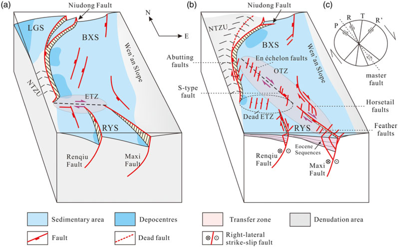
The boundary faults commonly curve into transfer segments with strike-slip or oblique-slip components within the two-phase transfer zones (Faulds & Varga, Reference Faulds and Varga1998). The transverse faults mainly formed in the transfer zone in the appropriate time and space in this study. The Niudong Fault includes the NW–SE-trending transfer segments (Maobei Fault) with oblique-slip or strike-slip motion within the Eocene transfer zone (Figs 5, 7d, 12a); however, the transfer segment does not inherit from the deep sequences (Tg) in the shallow surface (T3) (Figs 7d, 8, 12b). The northern N–S-trending Maxi Fault acts as the transverse segment with strike-slip motion in the Oligocene succession (Figs 10c, 11b, 12b). Movement along the transfer fault generally accommodates the relative motion, rather than the apparent separation, between adjoining domains (Faulds & Varga, Reference Faulds and Varga1998). The Maxi Fault is therefore observed as a dextral strike-slip fault according to the movement directions of the two walls of the fault blocks (Fig. 11b). In addition, the fault linkage styles between the Maxi Fault and the secondary faults also suggest dextral strike-slip motion.

Fig. 12. Simplified models showing fault geometries during (a) Eocene and (b) Oligocene time in the study area. BXS – Baxian Sag; ETZ – Eocene transfer zone; LGS – Langgu Sag; NTZU – Niutuozhen Uplift; OTZ – Oligocene transfer zone; RYS – Raoyang Sag. The small arrows represent the strike-slip direction of faults or strata. (c) Fracture structures superimposed on a dextral strain ellipse. P – P shear (secondary synthetic shear); R – Riedel shear; R′ – conjugate Riedel shear; T – tension fracture.
The internal fault styles are also different between the Eocene and Oligocene surfaces within the two transfer zones (Figs 5, 8). In the Eocene transfer zone, the NW-striking and NNE-striking faults interact and link to form an orthogonal fault complex in the deep surface (Figs 5, 12a), while numerous NE-striking conjugate faults form in the shallow part (Figs 8, 12b). The displacement of the Niudong Fault is transferred to Renqiu and Maxi faults through the NW-striking and NNE-striking linking faults. The NW-striking faults act as minor transfer faults linking NNE-striking normal faults. In the Oligocene transfer zone, the characteristics of fault superposition are different between the north and south parts. In the north part, new sets of numerous, short-strike-length, low-displacement faults (Fig. 12b) are superimposed on several NE-trending, long-strike-length, high-displacement faults which are nearly parallel (Fig. 12a). The observation that part of the NE-striking secondary faults abut the NNE-striking central segment of the Niudong Fault (‘abutting faults’ in Fig. 12b) at an angle of 45–80° in the Oligocene surface (Figs 8, 12b) suggests that the central segment is the dextral oblique-slip fault with a strike-slip component (Fig. 12b). This is because the central segment can be regarded as a dextral master fault while the abutting faults could be composed partly of T fractures and R′ shears (Fig. 12c). In addition, many NE-striking secondary faults comprise en échelon fault belts (Figs 8, 12b) within the northern Oligocene transfer zone (Figs 8, 12b), indicating a dextral strike-slip motion. In the south part of the transfer zone, the deep surface is characterized by several approximately N–S-striking faults and a few NW–SE-striking faults that only form in the Eocene transfer zone (Figs 5, 12a). However, new sets of numerous, short-strike-length, low-displacement ENE-striking faults intersect the early S–N-trending faults at a large angle (60–80°) and form S-type, feather or horsetail faults in the Oligocene sequence (Figs 8, 12b). The secondary fault groups could be composed partly of T fractures and R′ shears together under a dextral strike-slip motion (Fig. 12c).
Transfer zones most commonly comprise steeply dipping faults that include boundary fault segments and minor faults with a strike-slip component (Gawthorpe & Hurst, Reference Gawthorpe and Hurst1993; Faulds & Varga, Reference Faulds and Varga1998). The Eocene and Oligocene transfer zones include different transverse boundary fault segments with strike-slip motion in the surfaces (Fig. 12). The transverse boundary fault tip transfers strain directly when and where the transfer zone forms. The boundary fault segments, that is, the central segment of the Niudong Fault and the northern Maxi Fault, are evident as rift-parallel faults in the Eocene and strike-slip faults in the Oligocene sequences. As for the internal faults, the fault styles which are related to strike-slip motion only occur in the sequence where the transfer zone forms, such as the NW-striking minor transfer faults within the orthogonal fault complex (Moustafa, Reference Moustafa2002; Yang, Reference Yang2009) in the Eocene sequences, en échelon step faulting (Moustafa, Reference Moustafa2002) in the northern Oligocene transfer zone, and S-type, feather or horsetail faults in the southern Oligocene transfer zone.
The characteristics of structural frameworks and fault systems are different between the Eocene and Oligocene sequences (Huang et al. 2012b; Tong et al. Reference Tong, Zhao, Cao, Liu, Xiaomei and Zhao2013; Liang et al. Reference Liang, Yu, Liu, Wang, Li and Ma2014; Chen et al. Reference Chen, Ren, Xin, Zhang and Wu2015; Zhang et al. Reference Zhang, Wu, Zhou, Niu, Li, Ren and Zhang2017). Transfer zones result from the heterogeneous distribution of strain within extended terranes and commonly serve as transform-like structures that link spatially distinct domains of extension (Faulds & Varga, Reference Faulds and Varga1998). Based on the analysis of the basin architectures and fault geometries between the two-phase rift sequences, we recognized the two-phase transfer zones in the Eocene and Oligocene sequences. The two-phase transfer zone also provides valuable understanding of fault geometry evolution and the formation mechanism of the two-phase faults in the two-phase rift. The defined two-phase transfer zone in this example may be used as a model when studying fault geometries in multiphase rift basins elsewhere, especially where the extension direction varies with each rift phase. Caution must be exercised when using the proposed models in new multiphase rift basins; the existence of curved, basin-controlled boundary faults is a necessary condition, as these have a significant influence on the internal fault geometries during multiphase rift. For example, the model is not applicable to rift basins that develop widespread major fault arrays (e.g. the Bonaparte Basin in Australia; Frankowicz & McClay, Reference Frankowicz and McClay2010).
6.c. Influence of the two-phase transfer zones on sedimentation
Normal faults in rift basins are often connected to a linked fault system (Gibbs, Reference Gibbs1990) that has a significant influence on sediment deposition (Schlische, Reference Schlische1991; Gawthorpe & Leeder, Reference Gawthorpe and Leeder2000; Scholz & Hutchinson, Reference Scholz and Hutchinson2000; Contreras & Scholz, Reference Contreras and Scholz2001; Athmer & Luthi, Reference Athmer and Luthi2011; Ge et al. Reference Ge, Zhu, Wang, Jones and Chen2018). As displacement on the two divergent faults progressively decreases toward the transfer zone, two oppositely tilted half-grabens, the upthrown parts of individual fault blocks and major footwall uplifts along the margins of the extended terrane collectively terminate in the along-strike dimension. The transfer zone therefore represents structural and topographic highs with respect to the two half-grabens, and structural and topographic lows relative to the upthrown parts of fault blocks and footwall uplifts. Drainage development, sediment transport pathways and entry points will undoubtedly be affected by extensional fault systems in rift basins, and the transfer zone often acts as an entry point for syn-rift deltas and fan deltas that prograde axially into an adjacent half-graben (Faulds & Varga, Reference Faulds and Varga1998; Younes & McClay, Reference Younes and McClay2002; Qi, Reference Qi2007; Hou et al. Reference Hou and Sheng2010; Wang et al. Reference Wang, Wang, Ren, Xiao and Pu2010; Moustafa & Khalil, Reference Moustafa and Khalil2017). However, the basin architecture changed during the two-phase rift in this study, so that the new transfer zone did not inherit from the previous transfer zone but formed in a new location. Based on the above results, we can infer that the transfer zone does not continuously influence the sedimentation in the whole rift stage, but mainly affects the sedimentation in the period of formation. Two representative contour map examples of sandstone percentage are presented in Figure 13 to show the distribution characteristics of sandstone, with particular emphasis on the difference of drainage catchments within the transfer zones during Eocene and Oligocene time. The first example is from a contour map of Es 4s (the upper submember of Es 4), representative of Eocene structural layers. The second example is from a contour map of Ed 3 (the third member of Dongying Formation), typical of Oligocene structural layers. It is difficult to understand the whole evolution process of drainage catchments based on only two maps; we have therefore emphasized the differences between drainage catchments and considered the influence of the transfer zone on sedimentation.
The characteristics of the drainage catchments in the west of the Eocene transfer zone are useful to understand the influence of the transfer zone on sedimentation during multiphase rift. The lobed sandstone sediments, which developed in the west part of the Eocene transfer zone and extend to the subsidence area, are observed to have different properties regarding the percentage content of sandstone and sediment dispersal paths in the sandstone percentage contour maps (Fig. 13). (1) The fan-shaped sandstone sediments drained into the Eocene transfer zone from the west with a maximum sandstone percentage of 40–50% in the deep sequence (Fig. 13a) and 20–30% in the shallow sequence (Fig. 13b). (2) The fan-shaped range (e.g. > 10%) in the shallow sequence is smaller than that of Es 4s. (3) The lobed sandstone sediments and the related entry point moved south from the deep sequence to the shallow sequence. (4) The sediments drained into the subsidence area in three directions during Eocene time (in the hanging walls of the Baxian Sag and Raoyang Sag, and the centre of the transfer zone), while pushing towards the area in two directions during Oligocene time (in the hanging wall of the Renqiu Fault). These differences imply that there was a large drainage system during Eocene time in the SW of the Eocene transfer zone where the delta or fan-delta constantly pushed either forwards or backwards (Xie & Deng, Reference Xie and Deng2008), while early sediment transport pathways gradually migrated southwards and became obsolete during Oligocene time. The transfer zone is therefore an important entry point for lager alluvial fans, fan deltas and sand-rich deposits, where the zone acts as an efficient transfer of strain from normal-fault systems.

Fig. 13. Sandstone percentage contour maps of (a) Es 4 and (b) Ed 3 in the study area. C – central segment; N – north segment; S – south segment of the Niudong Fault. ETZ – Eocene transfer zone; OTZ – Oligocene transfer zone.
6.d. Implications for hydrocarbon exploration
Palaeogene rifting in the Baxian Sag created a petroleum system that is in its mature exploration phase (Min et al. Reference Min, Xin, Zhang, Lv and Li2015). The structural pattern, distribution area and thickness of the sandstone were affected by the transfer zone, which further affected reservoir properties. The central and north (Ertaijie Fault) segments of the Niudong Fault controlled the early south depocentre and the later NE depocentre, respectively (Figs 6, 9), and further controlled the range of source rocks (Zhao et al. Reference Zhao, Liu, Jin, Jin and Zhang2015). Mature source rocks are mainly found in the Es 4 and Es 3 in the early depocentres, and the low mature source rocks in Es 1 are located in the later depocentre in the Baxian Sag (Zhao et al. Reference Zhao, Liu, Jin, Jin and Zhang2015). Hydrocarbon reservoir rocks vary in age and lithology, including pre-rift fractured limestone and syn-rift Cenozoic sandstone (Zhao et al. Reference Zhao, Jin, Cui, Han, Zeng, Wang and Guo2012; Zhang et al. Reference Zhang, Li, Zhai, Wang, Liu, Nie and Zhou2012). Top seals are dominantly pre-rift shales and tight carbonate rocks in addition to syn-rift shales (Zhao et al. Reference Zhao, Jin, Cui, Han, Zeng, Wang and Guo2012).
A large number of normal, strike-slip and oblique-slip faults formed in the transfer zones to transfer displacement of the two bounding faults (Figs 5, 8). Many faults occur in the Eocene sequences and basement within the Eocene transfer zone. All of these faults induced multiple tectonic fractures in the basal carbonate strata (e.g. Cambrian and Ordovician), which formed the interconnected fracture network system (Lao et al. Reference Lao, Wu, Chen and Wu2012). The multistage faulting is helpful in increasing space and thickness in the carbonate reservoir. These types of reservoirs are good oil and gas accumulation areas in deep carbonate-buried hills (Lao et al. Reference Lao, Wu, Chen and Wu2012; Zhao et al. Reference Zhao, Jin, Cui, Han, Zeng, Wang and Guo2012, Reference Zhao, Liu, Jin, Jin and Zhang2015).
The evolution of the Eocene transfer zone also resulted in distinct differences in the characteristics of the sandstone bodies and physical properties of the reservoir. The delta distributary channels extended to the Eocene transfer zone (Fig. 13a), in which the single sand body is characterized by a large thickness and high ratio of sand to shale during Eocene time (Lao et al. Reference Lao, Wu, Chen and Wu2012). However, the distributary channels are characterized by rapid migration, thinner single sand body thicknesses and thinner reservoir thicknesses during Oligocene time (Lao et al. Reference Lao, Wu, Chen and Wu2012; Fig. 13b). Petroleum companies have confirmed that the Eocene formations are the more favourable for hydrocarbon accumulation within the transfer zone.
The Oligocene transfer zone is characterized by the N–S-striking gentle anticline uplifting superimposed on the early depocentre in the Baxian Sag, which primarily deposited fine-grained mudstone in the Eocene sequences (Zhao et al. Reference Zhao, Jin, Wang, Zhang, Wang and Bai2011) and many lobate sandstone bodies with good reservoir properties in the Oligocene sequences (Xie & Deng, Reference Xie and Deng2008; Fig. 10b). A large number of normal and strike-slip faults generate within the north part of the Oligocene transfer zone (Fig. 7), and some cut into the source rocks of Es 4 and Es 3 (Zhao et al. Reference Zhao, Jin, Wang, Zhang, Wang and Bai2011). These faults improved the physical reservoir properties, but also connected the shallow reservoirs and the deep source rocks, which is beneficial to hydrocarbon accumulation.
Transfer zones have been proven to be good locations for hydrocarbon traps in rifts in many natural examples (Morley et al. Reference Morley, Nelson, Patton and Munn1990; Gawthorpe & Hurst, Reference Gawthorpe and Hurst1993; Wang et al. Reference Wang, Lu, Fu, Sun, Wang and Li2013; Qi, Reference Qi2007; Moustafa & Khalil, Reference Moustafa and Khalil2017). However, little is known about the relationship between the location of the hydrocarbon traps and the location of the transfer zone during each sub-rift phase of a multiphase rift. In this study, the Eocene and Oligocene transfer zones are validated as the optimum location for hydrocarbon accumulation in the Eocene and Oligocene sequences, respectively. The formation and evolution of the transfer zone, as well as the impact on structural geometries and sedimentary patterns, should therefore be the focus for hydrocarbon exploration in multiphase rift basins.
7. Conclusions
(1) The structural-stratigraphic architectures of the Baxian and Raoyang sags changed during Eocene–Oligocene time to an oppositely tilted S-type fault system, which may be related to the change of extension direction. The two-phase transfer zones are identified based on the two different structural-stratigraphic architectures and fault systems in the Eocene and Oligocene sequences.
(2) The transfer zones form in the juxtaposition of differentially extended domains in different periods. The NW–SE-trending Eocene transfer zone links the northern W-tilted Baxian Block and E-tilted Raoyang Block in the Eocene sequences, whereas the N–S-trending Oligocene transfer zone results from the interference between the eastern N-tilted and western S-tilted fault domains. The latter formed along the inner kinks of the S-type bounding faults, linking the S-dipping northern segment of the Niudong Fault and N-dipping south segment of the Maxi Fault, and separating the early subsidence area into eastern and western parts.
(3) The two-phase transfer zones comprise different transverse boundary fault segments with strike-slip motion between the Eocene and Oligocene sequences, such as south segments of the Niudong Fault (Maobei Fault) in the Eocene surface and the northern Maxi Fault in the Oligocene surface. The internal fault styles which are related to strike-slip motion only occur in the sequence where the transfer zone forms, such as NW-striking minor transfer faults intersecting with the NE-striking normal faults in the Eocene sequences, and en échelon, S-type, feather and horsetail faults in the Oligocene transfer zone.
(4) The two-phase transfer zones significantly influenced the evolution of syn-rift sediments and drainage catchments within the transfer zones. For example, the Eocene transfer zone was the important entry point for large alluvial fans and fan deltas during Eocene time, while its control on sediments was significantly weakened during Oligocene time.
(5) The Eocene and Oligocene transfer zones are validated as the optimum locations for hydrocarbon accumulation in the Eocene sequences and Oligocene sequences, respectively.
Author ORCIDs
Bingshan Ma, 0000-0003-3289-796X
Acknowledgements
This research was financially supported by National Natural Science Foundation of China (grant no. 41572202). We thank the PetroChina Huabei Oilfield Company for providing 3D seismic data and other data. Olivier Lacombe, Guido Schreurs and one anonymous reviewer are thanked for their constructive reviews that significantly improved the manuscript. We are grateful to Shi Chen and Tong Sun for beneficial reviews of this manuscript and several valuable discussions.