1. Introduction and geological background
Columnar jointing is one of the most spectacular of rock formations and has long fascinated geologists and physicists since the first scientific report of the phenomenon to the Royal Society (Bulkeley, Reference Bulkeley1693). Since then columnar joints, formed as a consequence of cooling, have been widely documented (Mallet, Reference Mallet1875; James, Reference James1920; Tomkeieff, Reference Tomkeieff1940; Beard, Reference Beard1959; Smalley, Reference Smalley1966; DeGraff & Aydin, Reference DeGraff and Aydin1987; Aydin & DeGraff, Reference Aydin and DeGraff1988; Budkewitsch & Robin, Reference Budkewitsch and Robin1994; Grossenbacher & McDuffie, Reference Grossenbacher and McDuffie1995; Goehring & Morris, Reference Goehring and Morris2008; Hetenyi et al. Reference Hetenyi, Taisne, Garel, Médard, Bosshard and Mattsson2012; Phillips et al. Reference Phillips, Humphreys, Daniels, Brown and Witham2013; Moore, Reference Moore2019). Polygonal two-dimensional desiccation structures also form in clay-rich sediments due to shrinkage, and three-dimensional columns have been produced in laboratory experiments in which corn starch is dried (Goehring et al. Reference Goehring, Lin and Morris2006). Columnar structures in sedimentary and tuffaceous rocks are less widely reported (Buist, Reference Buist1980; Young, Reference Young2008; Gomes et al. Reference Gomes, Castillo Clerici, Gadea and Comin-Chiaramonti2014). A remarkable outcrop of columnar-jointed tuffaceous sedimentary rock occurs within the Lower Carboniferous rocks of the Peak District (Wilkinson, Reference Wilkinson, Neves and Downie1967) adjacent to the Tideswell Dale Sill and is the topic of this study.
During the Lower Carboniferous, Britain at a palaeolatitude of 20° to 15° S (Piper et al. Reference Piper, Atkinson, Norris and Thomas1991; Domeier & Torsvik, Reference Domeier and Torsvik2014) consisted of a carbonate platform of 500 km2 with contemporaneous basalt lavas and intrusions. The study area lies in SE Derbyshire in the Peak District National Park close to the village of Tideswell (Fig. 1). The now abandoned quarry (SK 155745) was originally worked around 1850 for the marble underlying the Tideswell Dale dolerite sill. Eventually the sill was quarried for road metal (Sarjeant, Reference Sarjeant1967). Fine-grained brick-red to purple-coloured rocks occur at the base of the quarry and contain a prominent horizon of columnar-jointed rock immediately below the sill.

Fig. 1. Map showing Tideswell and the surrounding area. Lavas, sills and other volcanic rocks are shown, including the Lower Miller’s Dale Lava (LMB) and the Tideswell Dale Sill (TDS) at the study locality just to the south of the village of Tideswell. Map modified after Macdonald et al. (Reference MacDonald, Gass, Thorpe and Gass1984).
Arnold-Bemrose (Reference Arnold-Bemrose1899) described the geology of the site, observing that the dolerite sill was in contact with either a red clay horizon or marmorized limestone at its base. Arnold-Bemrose (Reference Arnold-Bemrose1907) classified the Tideswell Dale Sill as olivine dolerite. Further work on the sill includes geochemical data (MacDonald et al. Reference MacDonald, Gass, Thorpe and Gass1984), petrography (Aitkinhead et al. Reference Aitkinhead, Chisholm and Stevenson1985) and geology (Waters, Reference Waters, Stephenson, Williamson, Loughlin, Millward and Waters2005).
The underlying Bee Low Limestone Formation gives an Asbian age (∼330–334 Ma) on the basis of coral and foraminifera assemblages typical of the late lower Dibunophyllum (D1) Zone, with the upper part containing Davidsonina septosa and ammonoid fauna indicative of the B2b Subzone (Stevenson & Gaunt, Reference Stevenson and Gaunt1971; Waters, Reference Waters, Stephenson, Williamson, Loughlin, Millward and Waters2005; CN Waters, pers. comm., 2007). The sill was dated by the whole-rock K–Ar method by Fitch et al. (Reference Fitch, Miller and Williams1970) at 287 ± 13 Ma (293 Ma with new constants; Waters, Reference Waters, Stephenson, Williamson, Loughlin, Millward and Waters2005), while the Upper Miller’s Dale Lava was dated at 315 ± 12 Ma. These ages are considered suspect, because they place the sill and lava at the end of the Upper Carboniferous into the Permian rather than in the Lower Carboniferous. Fitch et al. (Reference Fitch, Miller and Williams1970) attributed the young ages as the minimum age of hydrothermal alteration.
Brown (Reference Brown1870), Mello (Reference Mello1870) and Wilson (Reference Wilson1870) briefly described columnar-jointed rock beneath the sill and interpreted its origin as a volcanic mudflow altered by heating of the sill. Wilkinson (Reference Wilkinson, Neves and Downie1967) interpreted the columnar rocks as contact-metamorphosed volcanic ash. Waters (Reference Waters, Stephenson, Williamson, Loughlin, Millward and Waters2005) suggested that the columnar rocks were strongly weathered basaltic lava subsequently buried by lava and intruded by the sill.
The purpose of this study is to understand the origin of the columnar-jointed rock. The study includes consideration of: (i) the pre-metamorphic nature of the columnar rocks; (ii) the timing of their formation; (iii) the effects of metamorphism due to sill emplacement; and (iv) the mechanisms of column formation in sedimentary rocks.
The study may also have relevance to understanding the use of bentonites as an engineering barrier for the geological disposal of high-level radioactive waste. A major concern is that heating of bentonite by the waste might lead to changes in physical and chemical properties that compromise its effectiveness as a barrier. Thus clay-rich rocks affected by heating have been widely studied (e.g. Laine & Karttunen, Reference Laine and Karttunen2010; Reijonen & Alexander, Reference Reijonen and Alexander2015).
2. Field relationships
The locality occurs in a hollow at the south end of Tideswell Dale picnic area (Waters, Reference Waters, Stephenson, Williamson, Loughlin, Millward and Waters2005, fig. 7.2, site B). Excavation with a small mechanical digger exposed very fine-grained, brick-red to purple rocks in a trench c. 1 m deep by 2.5 m wide below the sill (Fig. 2). These rocks lack bedding, internal structures and fossils (Fig. 3). Rocks below the sill display three zones of different fracture geometry, whose boundaries dip c. 10° E.

Fig. 2. Outcrop sketch of study site looking NNE showing trench and sampling positions and numbers. Trench is 1 m deep. Total height of outcrop is 3.5 m (excluding depth of trench). Sample TD16 was collected from loose material on the ground next to the trench.

Fig. 3. (a) Photograph of the columnar rocks (60 cm high) in the excavation pit. (Hammer 35 cm long.) Contact with the overlying sill is just above the top of the picture. The columns do not continue right up to the boundary or deeper than 80 cm into the pit. A brown alteration product can be seen coating some columns. (b) Six-sided column defining maximum column width as marked by arrow. Ten pence coin for scale.
The upper fracture zone (30 to 40 cm thick) is in contact with overlying basaltic rock and displays prismatic jointing characterized by near-vertical curving fracture surfaces several cm in width, which bound individual prisms (Fig. 3a). Some of the prismatic fracture surfaces can be traced continuously into surfaces in the middle columnar-jointed zone. The middle zone of columnar jointed rock (c. 60 cm thick) is slightly curved (Fig. 3a). The column widths are a few cm; detailed data are presented in the results section below. The column surfaces are, in places, coated in a pale creamy material with pale grey-yellow fibres parallel to the column length. Minor white veins are observed in some columns. The polygonal columns are well developed, with sharp edges between fracture surfaces (Fig. 3b). The columns are slanted (Fig. 3a), with column axes or edges plunging 60° to 70° SW, having mean Pl = 64° and Az = 215°. The lower zone of non-columnar rock is characterized by a hackly irregular fracture system with curving conchoidal fracture surfaces bounding irregular blocks a few cm wide (Fig. 3a). The transition between well-organized columns and irregular blocks is fairly abrupt, but the broken-up character of the lower zone obscures the relationship.
The dolerite forms a craggy outcrop, 3–3.5 m high, and is part of a 20 m thick sill (Fig. 2). The upper sill contact is not exposed. About 1 m thickness of vesicular-altered basalt separates the columnar-jointed rocks from the overlying sill and is interpreted in Waters (Reference Waters, Stephenson, Williamson, Loughlin, Millward and Waters2005) to be part of the Lower Miller’s Dale Lava. The basal margin of the lava (2 to 4 cm thick) in contact with the columnar rocks is vesicular (vesicle size is 0.5–6.0 mm) and very fine-grained.
3. Methods
3.a. Field data and sample collection
The location and geological units of 25 samples are shown in Figure 2. Sample TD15 was an entire column sample (TD15/1–15/7). Samples TD6–10, 13, 14 and 19 were oriented and marked for palaeomagnetic analyses. Most hand specimens of columns were 5 to 15 cm in length. Samples of columns are extremely fine-grained, fragile rocks, disintegrating easily, especially in contact with water. Parameters measured in the field are total number of sides per column (N = 114) and column width (N = 100), defined as the greatest distance between any two corners in cross-sectional view (Fig. 3b). An additional 39 random samples were collected for geometrical measurements in the laboratory.
3.b. Compositional analyses
Techniques included: petrography; X-ray diffraction (XRD) at Edinburgh University and the Natural History Museum, London; X-ray fluorescence (XRF) of whole-rock compositions at Leicester University; and scanning electron microscope (SEM) and electron micro probe analyses (EMPA) at Bristol University.
3.b.1. XRD analyses
XRD scans at Edinburgh were carried out on a Bruker AXS D8 Series 2 Powder Diffractometer, running at 40 kV and 40 mA, with a Cu source, a germanium monochromator, a 2 mm exit slit, and a 0.2° divergence slit. Oriented mounts of a selection of seven samples (Table 1) were prepared on glass slides. The samples were analysed both air-dried and after ethylene glycol solvation. Each sample was scanned from 3° to 35° 2θ for 30 min with a step size of 0.014°. Elevated background levels were observed due to secondary Fe fluorescence of the hematite-bearing samples, with Cu radiation making the analysis of clay minerals and minor phases more difficult. Therefore, additional XRD measurements were carried out using Co radiation, which has no fluorescence problem with Fe-containing samples. The samples were analysed in a similar fashion on oriented powder mounts on glass slides at the Natural History Museum, London, using a Panalytical X’Pert Pro MPD equipped with a Co source operating at 40 kV and 40 mA, a primary and secondary Soller slit of 0.02 rad and a divergence slit of 0.25°. Measurements were collected using a step size of 0.017° 2θ. Apart from running samples after drying in air and ethylene glycol solvation, two samples (TD9 and 13) were analysed after a heat treatment at 375°C for 2 hours.
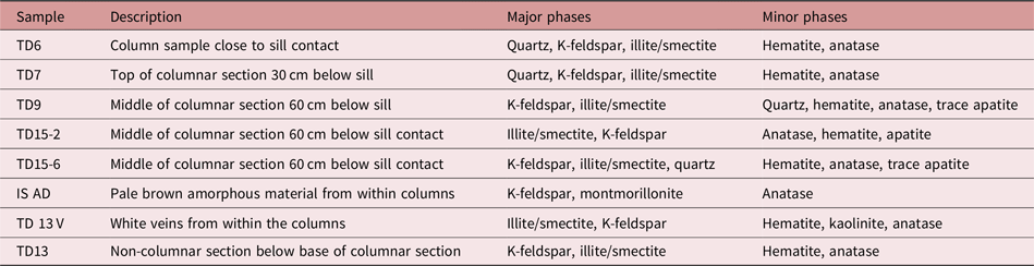
Table 1. Mineral identification from Edinburgh and NHM-XRD analyses. Sampling locations can be seen in Figure 2

*TD15-2 contains two illite/smectites of different composition.
3.b.2. SEM and EPMA analyses
A Hitachi S-3500 N SEM with an EDAX energy-dispersive X-ray analyser was used to obtain images of samples TD15/3 and TD14. Sample TD15/3 came from the middle of the columnar section 50 cm below the sill, and TD14 came from the non-columnar region at the bottom of the trench 130 cm below the sill (Fig. 2). The Cameca SX100 Electron Microprobe with five spectrometers and wavelength dispersive analysis was run at 20 kV and 4nT to analyse mineral phases. Average analyses are given in Table 2. Analytical uncertainties were assessed with secondary standards: Kakanui Kaersutite (USNM143965) and basaltic glass – USGS BCR2. Precision is ±1 % relative for majors and ±5–10 % relative for minor elements.
Table 2. Average EMPA composition of major phases in columnar rocks. The mineral formulae reconstructions assume Fe as Fe3+. The dark-phase reconstruction assumes two of the oxygens are associated with two hydrogens as in the ideal phyllosilicate structure

3.b.3. XRF analyses
Four powdered whole-rock samples were analysed by XRF for major and trace element contents on a Phillips PW1400 spectrometer using standard techniques described by Harvey et al. (Reference Harvey, Lovell, Brewer, Locke and Mansley1996). Analyses of international reference materials indicate that accuracy and precision are better than 0.5 % for major elements and better than 3 % for trace elements. Analyses are presented in Table 3. Modelling of mineral assemblages from whole-rock compositions used the Perple_X application suite (Connolly, Reference Connolly2005, Reference Connolly2009).
Table 3. XRF analyses of columnar jointed rocks. Major elements in weight percent and trace elements in ppm. Data for Tideswell Dale sill and Lower Millers Dale lava from MacDonald et al. (Reference MacDonald, Gass, Thorpe and Gass1984)

3.c. Geochronology
Step heating analyses were performed on two whole-rock aliquots (TD15/2 and TD15/4) with fragment sizes of 300–800 µm. Following crushing and sieving, each sample was mildly leached in dilute HNO3 and then hand-picked under a binocular microscope to remove any altered grains. Purified separates were loaded into copper packets, placed within quartz vials and then loaded into an aluminium can for irradiation. Packets of the international standard TCR (28.34 ± 0.16; Renne et al. Reference Renne, Karner and Ludwig1998) were interspersed with the Cu sample packets to permit characterization of the irradiation flux to the samples; J values assume ±0.5 % (1σ) precision. The samples were irradiated in the Petten HFR reactor for 12 hours, in the Cd-lined facility (RODEO).
Sample gases were extracted using a resistively heated double-vacuum furnace over a range of temperatures from 500 to 1600 °C, with the number of steps ranging from 12 to 25 per experiment. Furnace blanks were stable at less than 6 × 10⁻¹⁵ mol 40Ar, 2 × 10⁻¹⁶ mol 39Ar, 1 × 10⁻¹⁵ mol 38Ar, 6 × 10⁻¹⁷ mol 37Ar and 8 × 10⁻¹⁷ mol 36Ar. Data were collected on a MAP-215 mass spectrometer using a single faraday collector in peak-hopping mode. Peak intensities are regressed to sample inlet time using second-order polynomial regressions. All ratios are blank and mass-discrimination corrected. The data are presented in Table 4. For the ‘pseudo-plateau’ ages, uncertainties reflect the variability of the selected steps expanded by the square root of the mean square weighted deviation (MSWD). Air contamination of samples was minimal, ranging from 0.7 to 1.5 % atmospheric 40Ar.
Table 4. 39Ar/40Ar geochronological data and two samples of columnar-jointed rocks. Each sample was run in duplicate

* Error estimate multiplied by MSWD.
Table 5. Palaeomagnetic directions from Tideswell Dale site. Location of samples is shown in Figure 2

N = number of samples used in calculating the samples mean. Dec(°) = declination, and Inc(°) = inclination in situ. k = Fisher’s (1953) precision parameter. α95 = half-angle of the cone of 95 % confidence about the mean. For group statistics, abbreviations are as for the samples statistics except N = number of samples, Lat/Long = latitude and longitude of the corresponding palaeo-pole, dp and dm = semi-axes of 95 % confidence about the pole.
Group statistics

3.d. Palaeomagnetism
For palaeomagnetic studies, seven hand specimens of the columnar-jointed rock (TD6–10, 13–14) and one of the overlying sill (TD19) were oriented in the field using a magnetic compass. Nineteen specimens, comprising 2.3 cm cubes, were cut from the eight oriented samples. Before the samples were demagnetized, magnetic susceptibility was measured on a KLY-2 Kappabridge susceptibility meter, and the intensity of the Natural Remanent Magnetism (NRM) was measured on a 2G Cryogenic Magnetometer housed in a low-field (<200 nT) room.
All oriented specimens were subjected to progressive thermal demagnetization, using a furnace with a residual field <5 nT, in temperature steps of 30° or 50 °C (initial step was 100 °C), until the remaining intensity was <5 % of the initial NRM. Samples were monitored for possible alteration during demagnetization by measuring the bulk susceptibility after each temperature step. Demagnetization data were visually inspected on orthogonal and stereographic projections, and components of magnetization were determined using least-squares algorithms (Kirschvink, Reference Kirschvink1980). Magnetic components were considered stable where they were defined by at least three points on vector end-point diagrams and had a maximum angular deviation not exceeding 15°.
4. Results
4.a. Column analysis
The number of column sides ranged from four to seven (Fig. 4a), with a mean of 5.44, a median 5.5 and variance of 0.64. The most common column width was between 4.0 and 4.5 cm across (Fig. 4b). Overall column widths ranged from 2.5 to 6.5 cm (Fig. 4b), with a mean width of 4.1 cm, median of 4.0 cm and variance of 0.58 cm. Angles between column sides varied widely (Fig. 4c), with a mean angle of 119.2°, a value consistent with a mean of 5 for the number of sides. The hexagonality index (equation 2 in Budkewitsch & Robin, Reference Budkewitsch and Robin1994) is 0.78, indicating that the columns are at the well-organized end of the spectrum of basalt columns (Phillips et al. Reference Phillips, Humphreys, Daniels, Brown and Witham2013) and in desiccation experiments (Goehring & Morris, Reference Goehring and Morris2005).

Fig. 4. (a) Histogram for the number of column sides. (b) Histogram showing the maximum width of each column (see Fig. 3b for definition) with bins of 0.5 cm width. (c) Histogram showing angles between column sides in 10° bins.
4.b. Petrology and mineral geochemistry
The columnar rocks are very fine-grained, preventing identification of minerals or textures by petrological microscope. SEM images (Fig. 5a) show an intergrowth of two main mineral phases, with contrasted greyscales with grain sizes in the 1 to 10 µm range. The medium greyscale mineral (∼30–40 % of the rock) is potassium feldspar (Table 3); the mean of seven analyses gives Or95. The dark greyscale phase (∼45 % of the rock) contains ∼54 % SiO2, ∼28 % Al2O3, ∼5 % K2O, and approximately equal amounts of MgO and FeO (2.5 %). Low totals suggest c. 6 % H2O. Based on the stoichiometry of phyllosilicates (illite and micas) with 12 oxygens, and the average of 49 analyses (Table 2), the formula calculated is (K0.46 Na0.005 Ca0.05) (Al1.66MgO0.24 Fe0.14 Ti0.004) (Si3.51Al0.49] O10 (OH)2. The calculation assumes (OH)2 resulting in 4.63 % H2O and an average total of 99.2 %. The potassium feldspar forms patches and some well-shaped crystals embedded in the dark grey phase (Fig. 5a).

Fig. 5. SEM images from samples TD15/3 and TD14. (a) General view of TD15/3, 50 μm across; (b) expanded books of smectite, 60 μm across.
Clay minerals in samples TD15/3 and TD15/6 occur as expanded ‘books’ in small ‘pockets’ up to 400 µm in size, making up a few per cent of the rock. They commonly occur concentrated around the end of cracks (Fig. 5b). EPMA gives c. 20 % Al2O3 and 36 % SiO2. The mineral is identified as mixed-layer swelling clay in the smectite group, with 17–18 % non-interlayer cations such as Ti, Al, Fe, Mg and Mn at the octahedrally coordinated sites between the oxygen layers of brucite sheets (Schmidt & Robinson, Reference Schmidt and Robinson1997).
Apatite occurs in large swathes (up to several mm long) in some samples. Micro-concretionary nodules with apatite (Fig. 6a) are particularly abundant in the prismatically jointed rock. Hematite occurs in micron-scale clusters (Fig. 6b). Other minor phases include rutile, broken zircons (Fig. 6c), xenotime and monazite.

Fig. 6. SEM images from samples TD15/3 and TD14. (a) Micro-concretion of apatite surrounding hematite, surrounding apatite, 27 μm; (b) hematite cluster, 20 μm; (c) zoned fragment of zircon crystal, 18 μm.
XRD analyses of columnar rocks from the three zones (Table 1) show a sharp series of reflections in the 20–30° 2θ range (Fig. 7a) characteristic of alkali feldspar. Quartz is also identified, being particularly prominent in TD7. Hematite is identified from peaks at 33.2° 2θ CuKα and 24.1° 2θ CuKα. Minor anatase was detected in all samples. SEM and EPMA analyses show a major dark-grey phase (∼45 % modal abundance) with an illite-like composition. This phase was identified as illite/smectite in all samples measured with cobalt radiation (Fig. 8). Broad XRD peaks are characteristic of illite/smectite (at 11.7, 5.0 and 4.48 Å in air-dried and 12.6, 9.4, 5.20 and 4.48 Å in glycolated samples). The position of low-angle illite/smectite peaks indicates the presence of R1-type ordered interstratification with c. 30 % expandable smectite layers (Moore & Reynolds, Reference Moore and Reynolds1997). The percentage smectite is very similar throughout the series except for TD15-6 which also contains a minor mixed phase with >80 % smectite estimated. Brown patches within the columns show prominent alkali feldspar with minor anatase. White veins within the columns and from the brown surfaces also contain minor kaolinite (Fig. 7; Table 1),

Fig. 7. Selected XRD patterns. (a) TD9 non-glycolated sample; (b) TD7 non-glycolated sample; (c) TD15-6 AD non-glycolated sample; (d) TD13 glycolated sample; (e) TD13V sample of white veins. Data were collected using CuKα radiation and background subtracted.

Fig. 8. (a) XRD patterns of selected samples (air-dried) from non-columnar base (TD13) and top (TD6), columnar section (TD7, 9, 15-2, 15-6), and white veins from within the columns (IS). (b) XRD patterns of selected samples (glycolated) from non-columnar base (TD13) and top (TD6), columnar section (TD7, 9, 15-2, 15-6), white veins from within the columns (IS), and after heat treatment at 375 ºC (TD9 and 13). D values in Å are given for characteristic illite/smectite peaks. Q is quartz, Kf is K-feldspar, IS is illite/smectite, dIS is dehydrated illite/smectite, H is hematite, Ka is kaolinite and A is anatase. Data were collected using CoKα radiation and background subtracted.
4.c. Geochemistry
Whole-rock geochemistry of three samples (Table 3) has SiO2 comparable to basic igneous rocks (47.1–49.7 %), but one (TD7) located near the contact with overlying basalt lava has much higher SiO2 (59.3 %). Based on total alkalis and SiO2, these samples classify as trachybasalts and trachyandesites, but other aspects of their geochemistry are unlike common fresh volcanic rock compositions. In comparison to common mafic igneous rocks, including Carboniferous lavas and sills of Derbyshire (Table 3), the three samples with SiO2 < 50 % have high K2O, Al2O3 and Fe2O3 contents, but very low MgO, Na2O and CaO. TD7 has similarities to trachyte, except for the very low Na2O content.
The trace-element geochemistry shows that the columnar rocks are not closely related to the associated basalt lavas and dolerite sills. Ba contents (800–900 ppm) and Rb contents (90–140 ppm) are several times higher than the typical Carboniferous basalts (MacDonald et al. Reference MacDonald, Gass, Thorpe and Gass1984). Th, U and Y concentrations are similar to intermediate to evolved alkaline volcanic rocks (Wilson, Reference Wilson1989). Th is much higher (Th 13–14 ppm) in the samples with SiO2 < 50 % than in the Miller’s Dale Lavas (Th 1.2–2.1 ppm; MacDonald et al. Reference MacDonald, Gass, Thorpe and Gass1984). The Y concentrations of 32–48 ppm reflect abundance of apatite shown by the SEM and XRD analyses. Zr values of 140–180 ppm are similar to basalt and are not easily reconciled with the presence of zircon crystals, since the observed Zr values are too low to crystallize magmatic zircon. The values of Ni (20–40 ppm) and Cr (110–130 ppm) are lower than typically found in Derbyshire Carboniferous mafic rocks (MacDonald et al. Reference MacDonald, Gass, Thorpe and Gass1984), but higher than found in evolved alkaline volcanic rocks. We infer that the columnar rocks have similarities to felsic volcanic compositions, but trace element composition features which reflect alteration and presence of detrital minerals.
4.d. Geochronology
Geochronological data are summarized in Table 4 and displayed in Figure 9. Step-heating age spectra show disturbed patterns of older ages in low-temperature steps, a pseudo-plateau region at c. 350 Ma, and a decrease in ages for high-temperature steps. Data defining the pseudo-plateau ages do not conform to accepted criteria for plateau ages (as is), but are chosen based on similarity of step ages within and between analytical runs. The pseudo-plateau ages agree within calculated uncertainties, which depend on analytical errors and uncertainty in the J factor. Relative to sample 15/2, sample 15/4 has higher apparent ages and lower overall K/Ca ratios, suggesting a geochemical or mineralogical control on age estimates. The disturbed spectra are likely the result of recoil processes within the fine-grained matrix of the samples (Foland et al. Reference Foland, Fleming, Heimann and Elliot1993; Dong et al. Reference Dong, Hall, Peacor and Halliday1995; Jourdan et al. Reference Jourdan, Matzel and Renne2007). Good agreement between pseudo-plateau and total-fusion ages for sample 15/2 suggest 345.7 ± 1.1 Ma as the best age estimate for the rock with columnar joints below the Tideswell Dale Sill.

Fig. 9. Age spectra of two samples of columnar-jointed rock (with duplicate analyses). All steps for each experiment are shown. Filled boxes indicate accepted ‘plateau’ steps. Open boxes show points excluded from the age calculation. Each experiment lists the total fusion age (±1σ). The data do not define plateaux, but the experiments show similar step-heating release patterns. We identify pseudo-plateaux in the latter half of each experiment that appear to yield sensible age information. These inferred pseudo-plateau ages are indistinguishable at ±1σ. The total fusion ages for sample 15/2 are also indistinguishable from the pseudo-plateaux, but are systematically older in sample 15/4 for each experiment. This may be a result of small differences in grain size of each, with sample 15/4 having undergone a greater amount of recoil.
This calculated age is significantly older than the Asbian (late Visean) stratigraphic age of 330–334 Ma for the Bee Low limestone, instead being close to an early Visean age (345.3 ± 2.1 Ma; Gradstein et al. Reference Gradstein, Ogg, Smith, Agterberg, Bleeker, Cooper, Davydov, Gibbard, Hinnov, House, Lourens, Luterbacher, McArthur, Melchin, Robb, Shergold, Villeneuve, Wardlaw, Ali, Brinkhuis, Hilgen, Hooker, Howarth, Knoll, Laskar, Monechi, Powell, Plumb, Raf, RoÈhl, Sanaflippo, Schmitz, Shackleton, Shields, Strauss, VanDam, Veizer, van Kolfschoten and Wilson2004). The anomalously old calculated ages probably do not result from excess 40Ar, given the high K content and estimated ages. Instead, they are attributed to recoil loss of 39Ar from the samples, which is expected in these very fine-grained (1–10 µm) rocks given experimentally observed recoil distances of c. 0.08 µm (Villa, Reference Villa1997). The +12 Ma to +16 Ma shift of total-fusion ages relative to the expected age of the sill and its metamorphic effects would result from a 5 % and 10 % loss of 39Ar from samples 15/2 and 15/4 respectively. The older ages might also reflect a contribution from older detrital components in the tuffaceous sediments.
4.e. Palaeomagnetic results
The dark reddish-purple colour of the samples, SEM studies and XRD show hematite as the only magnetic mineral present in the contact rocks. This finding is consistent with the results from the demagnetization experiments, where all the samples of the contact rock demagnetize by maximum temperatures of 690 °C (e.g. Fig. 10a, b). Specimens from sample TD19, from the sill itself, showed the largest drop in intensity between 500 and 630 °C (Fig. 10c), indicating that the major magnetic mineral phase present is likely maghemite or hematite. NRM intensities were typically in the range 80–160 mÅ m−1 for the contact samples, whereas the intensities for the samples from the sill itself were of the order 0.4–0.6 Å m−1. The response of the samples to progressive demagnetization proved to be straightforward. After removal of a small viscous component of magnetization, virtually all specimens revealed a characteristic component that trended to the origin on orthogonal plots (Fig. 10). This characteristic component was generally oriented to the NE with moderate downward inclinations, with the exception of the specimen from sample TD7, which yielded a shallow SE-directed component (Fig. 10 d). This direction was considered anomalous and is not further considered. The remaining seven samples yielded a mean declination of 054.7 and inclination of 41.1 (α95 = 19.6°) (Table 5). The associated pole (calculated using a present latitude of 53°16′02″ N and longitude of 1°46′09″ W for the site) lies at 39.6° N and longitude as 102.2° E (dp/dm = 14.2/23.8). This pole plots closest to latest Triassic poles for stable Europe (Fig. 11; Torsvik et al. Reference Torsvik, Van der Voo, Meert, Mosar and Walderburg2001), and contrasts with the results obtained by Piper et al. (Reference Piper, Atkinson, Norris and Thomas1991) from the Lower Carboniferous lavas of Derbyshire, including a sample of the fresh interior of the Tideswell Sill. Piper et al. (Reference Piper, Atkinson, Norris and Thomas1991) used their data to establish the Carboniferous palaeo-latitude. The volcanic rocks typically yielded a shallow SW-directed component of magnetization, consistent with the expected Lower Carboniferous palaeofield, though a number of sites in that study also recorded the NE direction reported here.

Fig. 10. Representative demagnetization data for samples from the contact rocks (a, b) and from the Tideswell Dale Sill (c). Solid and open symbols represent projections in the vertical and horizontal planes respectively. The stereographic projection (d) depicts the sample mean data, with solid symbols representing positive inclinations. Error circles are at the 95 % confidence level and are depicted in light grey for the individual samples, and in black for the overall mean direction (marked with a cross).

Fig. 11. Mesozoic polar wander path with pole position and oval of error from this investigation. The white path marks the Permian to Cretaceous apparent polar wander (APW) path for Europe and was generated using a moving window average through the reference palaeomagnetic data (Torsvik et al. Reference Torsvik, Van der Voo, Meert, Mosar and Walderburg2001). The errors on the path are of the order of 10°. The best overlap is with the Late Triassic / Early Jurassic, especially when the errors on the path are taken into account.
While we had originally hoped the palaeomagnetic data would provide an additional constraint on the age, the data reported here (Table 5) are not consistent with the expected Lower Carboniferous direction (e.g. Piper et al. Reference Piper, Atkinson, Norris and Thomas1991). The geochronological and stratigraphic data discount the possibility that the intrusion is much younger than the host rocks. The associated pole overlaps with the apparent polar wander (APW) path for Europe (Torsvik et al. Reference Torsvik, Van der Voo, Meert, Mosar and Walderburg2001) for the Late Triassic to Early Jurassic, although the mean pole is displaced slightly away from the path. While the underlying Bee Low Limestone is gently flexed locally, with dips up to 10° on the local site map in Waters (Reference Waters, Stephenson, Williamson, Loughlin, Millward and Waters2005), the sill itself appears approximately horizontal, but is locally transgressive. Tilting by up to 10° to the east cannot be discounted since the magnetization was acquired, but correction for this dip takes the pole further away from the reference path. We have therefore not applied any corrections for minor amounts of tilt. The most logical explanation for the palaeomagnetic data is that the samples have undergone a pervasive chemical remagnetization in the Late Triassic, which has obscured the original palaeomagnetic signal. This remagnetization was associated with the growth of new hematite phases and could be linked with extension of the Pangaean supercontinent in the late Triassic and Early Jurassic, resulting in the eventual splitting of North America from Europe at c. 150 Ma (Van der Pluijm & Marshak, Reference Van der Pluijm and Marshak1997). Early Jurassic extension in southern Britain with a NE–SW extension direction has been recognized from studies of fissure fills of late Triassic and early Jurassic sediment in Carboniferous limestone in the Wessex Basin and the Mendips (Wall & Jenkyns, Reference Wall and Jenkyns2004). We suggest that the alteration associated with the same extensional regime affected the Pennine area too. The chemical re-magnetization could reflect ingress of oxidizing waters during Late Triassic and early Jurassic extension.
5. Discussion
5.a. Protolith of the columnar-jointed rocks
Two hypotheses about the protolith of the columnar-jointed rocks are that their protolith was either basalt (Waters, Reference Waters, Stephenson, Williamson, Loughlin, Millward and Waters2005) or felsic volcanic ash altered to K-rich bentonite (Wilkinson, Reference Wilkinson, Neves and Downie1967). The geochemistry of the rocks (Table 3) has some features characteristic of laterites formed by intense weathering of basalt, which include enrichment in Al and Fe and depletion in alkalis, Mg and Ca (Nesbitt & Wilson, Reference Nesbitt and Wilson1992; Hill et al., Reference Hill, Worden and Meighan2001; Sak et al. Reference Sak, Navarre-Sitchler, Miller, Daniel, Gaillardet, Buss, Lebedeva and Brantley2010; Babechuk et al. Reference Babechuk, Widdowson and Kamb2014; Buss et al. Reference Buss, Lara, Moore, Kurtz, Schulz and White2017). However, a lack of remnant textures indicative of basic igneous rocks makes this explanation unsatisfactory. Laterites can develop by weathering of the upper surfaces of basalt lavas, but the columnar-jointed rocks are above limestones which are not suitable compositions to form laterite. In addition, K, Rb and Ba are characteristically leached during laterite formation, and typically K2O does not exceed 1 % (Sak et al. Reference Sak, Navarre-Sitchler, Miller, Daniel, Gaillardet, Buss, Lebedeva and Brantley2010). K is typically leached more quickly than Na (Nesbitt & Wilson, Reference Nesbitt and Wilson1992). The Tideswell Dale columnar rocks have high K, Rb and Ba contents manifested by very low Na and abundant alkali feldspar. Thus the observations are not what is expected in basalt weathering and so do not support the interpretation of Waters (Reference Waters, Stephenson, Williamson, Loughlin, Millward and Waters2005). One possibility is that these rocks were affected by K metasomatism prior to contact metamorphisms, with original kaolinite being converted to illite (Fedo et al. Reference Fedo, Nesbitt and Young1995). However, this mechanism requires formation of K-rich pore fluids which can develop, for example where a soil overlies granite. This situation seems incommensurate with the geological setting at Tideswell Dale.
The hypothesis that these rocks are K-rich bentonites fits the observations much better. K-rich bentonites are characteristic of marine alteration of felsic ash layers (Huff & Turkmenogl, Reference Huff and Turkmenogl1981; Christidis & Huff, Reference Christidis and Huff2009; Pointon et al. Reference Pointon, Chew, Delcambre and Sevastopulo2018). An origin from a felsic volcanic precursor can explain why K-rich phases, notably potassic alkali feldspar and mica, are so dominant. Ancillary evidence includes the very fine-grained nature of the rocks and the presence of zircon crystals which would not be expected during basalt alteration.
We infer that most of the original material was glass of trachytic to trachyandesitic composition. Felsic volcanic glass is susceptible to alteration to clay minerals. Branney & Sparks (Reference Branney and Sparks1990), for example, described trachytic pumice deposits in the Azores altered to allophane and halloysite. Very high K/Na ratio in altered volcanic glasses reflects cation exchange of K+ and Na+ between glass and hydrothermal fluids (Scott, Reference Scott1971; Sparks, Reference Sparks1988). The alteration can explain the high Al2O3, high Fe2O3 and low SiO2 by leaching. The high (relative to basalt) concentrations of incompatible trace elements (Rb, Ba and Th) are also consistent with alteration of felsic glass. Our interpretation is supported by the study of Pointon et al. (Reference Pointon, Chew, Delcambre and Sevastopulo2018) on Visean bentonites in Belgium, many of which have strikingly similar compositions to the Tidesdale rocks. Likewise the whole-rock compositions are similar to Silurian metadolerites (Bachelor, Reference Bachelor1999).
Some features of the rocks are not explained by alteration of felsic glass. Ni and Cr are elevated compared to typical trachytic or rhyolitic glasses (Wilson, Reference Wilson1989). A plausible explanation is the presence of basalt-derived detrital mineral grains, such as olivine and chrome spinel. Broken zircon and some rutile crystals also suggest a detrital component. These features thus suggest local reworking of basaltic material and the site trapping aeolian dust, as suggested by Pointon et al. (Reference Pointon, Chew, Delcambre and Sevastopulo2018) for Visean bentonites in Belgium. Aeolian transport can be a cause of metal enrichment (Brimhall et al. Reference Brimhall, Lewis, Ague, Dietrich, Hampel, Teague and Rix1988). High P is a characteristic of intermediate rather than felsic alkaline volcanic rocks, but such rocks have high Ti contents, whereas the Tideswell Dale rocks have low Ti. Nodular and micro-concretionary structures rich in apatite suggest a biogenic origin for the high P.
The recognition of bentonite at Tideswell Dale adds to knowledge of Visean volcanism in the UK. Visean volcanism is dominantly basaltic, but small plugs and vents of trachyte and rhyolite are known (Cameron & Stephenson, Reference Cameron and Stephenson1985; Waters et al. Reference Waters, Waters, Barclay and Davies2009). Bentonite clay layers have also been reported from Derbyshire previously, in the Bee Low Limestone Formation and Kevin Limestone Formation (Waters et al. Reference Waters, Waters, Barclay and Davies2009). Bentonites indicate regional explosive felsic volcanism.
5.b. Contact metamorphism
The two major phases in the brick-red to purple rocks, originally a bentonite formed by alteration of felsic volcanic glass, are alkali feldspar and interlayered illite/smectite with minor quartz, which we attribute to contact metamorphism. Pointon et al. (Reference Pointon, Chew, Delcambre and Sevastopulo2018) present XRD data on Visean bentonites from Belgium with similar geochemistry to the Tideswell Dale rocks and show that they predominantly consist of mixed-layer clays and kaolinites. We infer a similar mineral assemblage prior to contact metamorphism.
Constraints on metamorphic temperatures attained in the rocks below the sill can be estimated by comparing observed mineral assemblages with experimental data on the firing of clays (Grim & Bradley, Reference Grim and Bradley1940; McConville & Lee, Reference McConville and Lee2005). These studies observe that characteristic clay mineral XRD reflections can be preserved to temperatures up to 800 °C. At high temperatures clay minerals become dehydroxylated and the structure starts converting to new phases. Qualitative temperature bounds can be inferred from the preservation of smectite in the illite/smectite series. Nadeau & Reynolds (Reference Nadeau and Reynolds1981) reported changes in illite/smectite-bearing bentonite due to contact metamorphism by the Cerillos pluton, New Mexico, USA. Far from the intrusion, the bentonite consists of smectite. Near the contact, the percentage of smectite decreases to ∼50 % at the 100 °C isotherm and ∼90 % at the 300 °C isotherm, while interstratification of illite/smectite layers becomes more ordered. Mudstones heated by the Orciatico intrusion (Tuscany, Italy) develop a similar mineral assemblage (∼35 % K-feldspar, quartz and illite/smectite ∼ 0.5) to the Tideswell Dale rocks at estimated ambient temperatures between 150 and 300 °C (Pellegrini et al. Reference Pellegrini, Lombardi, Rochelle, Boisson, Parneix, von Maravic and Alexander1999). Examples of bentonites heated by intrusions and lavas (reviewed in Laine & Karttunen Reference Laine and Karttunen2010) do not show abundant alkali feldspar in cases where estimated temperatures are less than 200 °C.
Increasing temperature results in illitization of smectite in burial diagenesis (e.g. Perry & Hower, Reference Perry and Hower1972; Srodon & Eberl, Reference Srodon, Eberl and Ribbe1984: illite/smectite >100 °C has 10–20 % smectite). However, kinetics is slow at these low temperatures, e.g. hydrothermal experiments of bentonite with KCl solutions showed a decrease of the smectite content in illite/smectite from 85 % to 70 % after 180 days at 200 °C (Cuadros & Linares, Reference Cuadros and Linares1996). On the other hand, smectite clay dehydrates fast under dry conditions. A heat treatment of TD9 and 13 at 375 °C and 2 hours (Fig. 8b) shows the transformation of smectite to non-hydrated smectite having an illite-like XRD pattern. This result indicates that temperatures as high as 375 °C are unlikely unless the columns were rehydrated during cooling.
In the case of Tideswell Dale, the K-rich character of the original rock led to formation of abundant alkali feldspar together with dehydroylated clays as a consequence of heating by the sill. By application of Perple_X modelling (Connolly, Reference Connolly2005, Reference Connolly2009), we infer that abundant alkali feldspar develops at a temperature of 300 °C or above (Fig. 12). However, modelling suggests that the observed mineral assemblage is not in equilibrium since illite would disappear at 300 °C and aluminous phases such as andalusite, cordierite and biotite would become prominent under equilibrium conditions. We infer that the duration of the rocks at high temperature was too short to reach an equilibrium assemblage and the effects of heating were closer to the non-equilibrium case when clays are heated in the making of ceramics with dehydroxylation. The Perple_X calculations thus do not enable us to estimate how much above 300 °C the rocks were heated

Fig. 12. (a) Mineral assemblages and reaction boundaries in a system with bulk composition of TD15/6. (b) Modal mineralogy of TD15/6 equilibrium assemblage as a function temperature at a pressure of 2 atmospheres. Calculations were also done for two other bulk compositions, but the results are very similar so are not presented.
The hematite is interpreted as secondary, with well-formed crystals that we attribute to alteration processes long after contact metamorphism. This interpretation is supported by palaeomagnetic data giving a Triassic magnetization. The smectite books are also attributed to secondary alteration after contact metamorphism, since they form at the ends of cracks.
Additional constraints on contact metamorphic conditions come from application of conductive heat transfer models (Jaeger, Reference Jaeger, Hess and Poldervaart1968) and modelling of illitization (Pusch & Karnland, Reference Pusch and Karnland1988). Temperature within 1 to 2 m of a 3.5 m thick dolerite sill can reach 20 to 50 % of the sill emplacement temperature. Assuming the sill emplacement temperature was c. 1200 °C, temperatures of 240 to 600 °C could thus be expected in the bentonite. Using a thermal diffusivity of 5 × 10⁻⁷ m2 s−1, peak temperatures in the column zone would occur after 70 days. A peak temperature of 300 °C or slightly above is thus consistent with available constraints. Models of illitization in montmorillonite (Pusch & Karnland, Reference Pusch and Karnland1988) suggest that illite/smectite of c. 0.7 as observed in the Tideswell Dale rocks requires temperatures of at least 250 °C for a timescale of 70 days
5.c. Column formation
We consider the hypotheses that columnar joints below the Tideswell Dale Sill formed either by dehydration of bentonite during heating by the sill or by cooling of the contact-metamorphosed rocks. Columnar joints can form by shrinkage induced by loss of moisture and dehydration reactions of clay minerals, so they may be analogous to desiccation fractures formed naturally in sediments (Neal et al., Reference Neal, Langer and Kerr1968; Price & Cosgrove, Reference Price and Cosgrove1994; Weinberger, Reference Weinberger2001) and in experiments on corn starch (Goehring et al. Reference Goehring, Lin and Morris2006). Columnar joints in igneous rocks are caused by tensile stress generated by contraction during cooling, and are arranged perpendicular to the cooling surfaces. Factors affecting columnar-joint formation in igneous rocks include cooling rate, thermal expansivity, intrusion or lava geometry and rock strength (Aydin & DeGraff, Reference Aydin and DeGraff1988; Budkewitsch & Robin, Reference Budkewitsch and Robin1994; Toramaru & Matsumato, Reference Toramaru and Matsumato2004; Hetenyi et al. Reference Hetenyi, Taisne, Garel, Médard, Bosshard and Mattsson2012). The first two factors determine the increase in tensile stresses induced by cooling, while strength determines the threshold for failure and development of a polygonal fracture network.
The columnar-jointed bentonites at Tideswell Dale are divided into three zones of contrasted fracture architecture. The upper prismatically fractured zone resembles fracture systems developed at the margins of rapidly cooled lava bodies cooled from above and in externally cooled volcanic bombs (e.g. Dance et al. Reference Dance, Hancock, Sparks and Wallman2001; Phillips et al. Reference Phillips, Humphreys, Daniels, Brown and Witham2013). The middle and lower zones are analogous respectively to the upper colonnade and entablature zones observed in lavas and attributed to cooling from above (Hetenyi et al. Reference Hetenyi, Taisne, Garel, Médard, Bosshard and Mattsson2012; Phillips et al. Reference Phillips, Humphreys, Daniels, Brown and Witham2013). Similar fracture patterns are observed in desiccation experiments where more disordered fracture networks merge downwards into well-ordered columns through an abrupt transition (Goehring & Morris, Reference Goehring and Morris2005; Goehring et al. Reference Goehring, Lin and Morris2006). In all these cases, including Tideswell Dale, many fracture surfaces in the upper prismatically jointed zone can be continuously traced into fracture surfaces in the well-ordered columns below. The arrangement of zones thus indicates that the columns formed from the top down away from the sill. This is the opposite of the direction expected for conductive cooling at the base of a sill with the contact aureole losing heat to the rocks below. The relationship is thus more easily explained by dehydration reactions related to heating of bentonite by sill intrusion than by cooling of the bentonite horizon following contact metamorphism. We therefore conclude that at Tideswell Dale the contact metamorphism of bentonite has resulted in dehydration with formation of an assemblage of alkali feldspar and illite/smectite from an original clay mineral assemblage. These reactions involve large negative volume changes that generate tensile stresses that led to column formation.
Further support for a model related to prograde contact metamorphism arises from consideration of the cycle of heating and cooling associated with emplacement of a 20 m thick sill. In the heating stage, a thermal boundary of thickness x grows as (κt)1/2 for conductive heat transfer. The bentonite horizon is within c. 1 m of the sill contact, so the timescale is on the order of 10 days for typical thermal diffusivities. A timescale can also be estimated assuming that the Peclet number was 0.3, which allows the approximate speed of fracture formation to be calculated. Using κ = 5 × 10⁻⁷ m2 s−1 and L = 0.04 m, the columnar zone would have a fracture penetration speed of 0.135 m h−1. Thus a 60 cm thick columnar zone would be formed in less than 2 days. For columns formed in a cooling cycle, the timescale is given by the sill half-thickness (>1.75 m) and would be of order several weeks (Jaeger, Reference Jaeger, Hess and Poldervaart1968). In the cooling scenario, fracture speeds would be much slower and, based on the scaling theory, columns should be much wider than those observed. Thus the small columns are better explained by prograde contact metamorphism and fast fracture propagation during heating.
A final line of reasoning to support column formation by prograde metamorphism arises from considering column size. The Tideswell Dale columns are comparable in scale to those developed in some sedimentary rocks adjacent to igneous intrusions, such as the Ferrar dolerite sill, Antarctica (Splettstoesser & Jirsa, Reference Splettstoesser and Jirsa1985), and in fine-grained quartz sandstones from Areguá, Paraguay (Gomes et al. Reference Gomes, Castillo Clerici, Gadea and Comin-Chiaramonti2014). In comparison, columns in igneous rocks are characteristically much wider; Hetenyi et al. (Reference Hetenyi, Taisne, Garel, Médard, Bosshard and Mattsson2012) report a range of 8 to 338 cm from 23,889 measurements. Columns comparable in width to Tideswell Dale are observed in secondary columnar jointing developed in lavas under conditions of strong convective cooling (Moore, Reference Moore2019). In contrast, the Tideswell Dale columns are much larger than the mm-scale columns observed in evaporation experiments on corn starch (Goehring et al. Reference Goehring, Lin and Morris2006). These observations invite application of theories on column size.
According to recent experimental and theoretical investigations (Goehring et al. Reference Goehring, Lin and Morris2006, Reference Goehring, Mahadevan and Morris2009), the scale of columns is controlled by advective–diffusive processes characterized by the Peclet number, Pe, defined as Pe ∼ vL/κ. Here v is the velocity that the fracture network penetrates, L is the characteristic column width and κ is a diffusion coefficient. In the case of cooling without chemical reactions, κ t is the thermal diffusivity, while, for desiccation of starch, κ d is the diffusivity of water through a poroelastic medium. The velocity is not the instantaneous fracture propagation speed but the time-averaged speed of numerous small increments of fracture propagation. Field and experimental data (Goehring & Morris, Reference Goehring and Morris2008; Goehring et al. Reference Goehring, Mahadevan and Morris2009) suggest that Pe ∼ 0.3 and further that estimated values of v for lavas and small-scale experiments on drying out corn starch are similar in the range 0.1–1 µm s−1. The much smaller scale of columns in desiccation experiments compared to cooled lava suggests that κ d << κ t.
From the Peclet number the small size of the Tideswell Dale columns compared to those observed in igneous rocks could reflect lower diffusivity and high cooling rates resulting in fast fracture propagation speeds. Using thermal conductivity, specific heat and density measurements for bentonites (Tang et al. Reference Tang, Cui and Le2008) and basalts (Robertson, Reference Robertson1988), the thermal diffusivities of the two rock types vary by factors of a few and overlap, but bentonites tend to have lower thermal diffusivities, consistent with smaller columns by a cooling mechanism, However, thermal diffusivity differences seem too small to explain the much smaller size of the bentonite columns. Secondary columns are observed in basalts adjacent and normal to primary columns (Moore, Reference Moore2019). They can have sizes similar to the Tideswell Dale columns, but commonly increase in width away from the cooling surfaces. The secondary basalt columns are interpreted by Moore (Reference Moore2019) as the consequence of fast cooling by water circulation along the primary column fracture system. The Tideswell Dale columns are, however, primary and do not change width systematically. Rather we infer that the diffusive process relates to the dehydration reactions caused by prograde metamorphism of bentonite in which clay minerals are converted into anhydrous phases (alkali feldspar) and mica. The reaction involves a volume decrease, and the water generated is lost from the system so that tensile stresses are developed that cause the fracturing. Excess water escape leading to shrinkage is a diffusive process qualitatively analogous to the dehydration of corn starch. Using the Pe number, we infer that the effective diffusivity enabling excess water loss must have been intermediate between water loss from corn starch and rock thermal diffusivity.
5.d. Analogue for radioactive waste concepts
The concept of using bentonite as a barrier for geological disposal of high-level radioactive waste has generated great interest within the nuclear industry in natural analogues (Reijonen & Alexander, Reference Reijonen and Alexander2015). There is consequently a large literature (much published as industry reports and conference proceedings) on bentonites affected by igneous intrusions, including experimental, theoretical and geological analogue studies. The reasons why bentonites are attractive as a very effective barrier around waste packages are their very low permeability and the swelling properties of the constituent clay mineral. Our interpretation of the Tideswell Dale columns suggests that at elevated temperatures bentonites shrink rather than swell, as a consequence of mineral reactions and water loss resulting in fracture network development. Estimated peak temperatures in bentonite fills around radioactive-waste canisters are expected to be below 150 °C (Laine & Karttunen, Reference Laine and Karttunen2010). However, experiments on bentonites at temperatures up to 120 °C (Zhang et al. Reference Zhang, Conil and Armand2016) show contraction as well as swelling. Shrinkage driven by water loss and mineral reactions could form fracture networks and enhance permeability and so should be considered in evaluating the performance of bentonite as a barrier.
6. Conclusions
We have documented fine-grained columnar rocks beneath the Tideswell Dale dolerite sill. 40Ar/39Ar dates confirm the Lower Carboniferous age of the contact. However, the age is older than other stratigraphic and geochronological evidence and makes the contact age up to 15 My older than the age of the intrusion. This discrepancy is attributed to recoil loss of 39Ar, yielding anomalously older ages.
The columnar-jointed rocks have geochemical and petrological features that are characteristic of fine felsic tuffs (bentonite) possibly with admixed wind-blown mineral dusts. When the bentonites were intruded by the sill, contact metamorphism baked them, forming an assemblage of alkali feldspar, interlayered smectite/illite and minor quartz and hematite. The XRD patterns of clays indicate that the contact metamorphism dehydrated the original clays. Comparison of mineral assemblages observed in these rocks with non-equilibrium assemblages observed during experimental and natural heating of common clay minerals and calculated from equilibrium assemblages using the Perple_X modelling are consistent with contact metamorphic temperatures at or slightly above 300 °C. Conductive cooling models of sills indicate temperatures between 240 and 600 °C.
Zones of prismatic jointing overlie a 60 cm zone of small-scale (∼4 cm) columnar joints that merges into conchoidally fractured rock below. This zonal arrangement is comparable to the organization of zones observed in lavas cooled from above and desiccation experiments where corn starch is dried from above. Thus the column formation is attributed to shrinkage due to prograde contact metamorphism by the overlying sill with downward fracture propagation. This interpretation is consistent with models of columnar jointing formed by advective–diffusive processes (Goehring et al. Reference Goehring, Mahadevan and Morris2009). Column widths at Tideswell Dale are much smaller than observed in volcanic rocks formed by cooling. The small width is consistent with diffusive loss of excess water during dehydration reactions and associated volumetric shrinkage during contact metamorphism.
The columns have a single-component chemical remnant magnetism dominated by hematite. The poles give a consistent Triassic direction and inclination. The younger age is attributed to alteration by oxidizing fluids during Triassic rifting.
Our inference that columnar fracture networks form in bentonites by shrinkage caused by heating may have implications for the performance of bentonite-fill around high-level radioactive waste packages. Bentonites are attractive as a barrier in waste disposal concepts, due to their swelling properties, but shrinkage at higher temperatures related to water loss and volume-reducing mineral reactions might compromise their effectiveness.
Acknowledgements
This project was supported by English Nature (now Natural England) as a contribution to a project to investigate the geology of Tideswell Dale Geological Conservation Review site, which forms part of the Wye Valley Site of Special Scientific Interest. Nicola Mellor is thanked for help with XRD analyses, and Doug Robinson is thanked for help with interpreting the XRD patterns. The Peak District National Park Authority is thanked for providing access and logistical assistance with the excavations. The authors thank Colin Waters and Lucas Goehring for helpful comments and information. James DeGraff and an anonymous reviewer are thanked for their thoughtful comments and suggestions, which improved the manuscript. R.S.J.S. was supported by a Royal Society Wolfson Merit Award and carried out further research supported by an Edward Bass Scholarship at Yale University. Jay Ague and David Evans at Yale are thanked for helpful discussions. We thank Ray MacDonald, David Peate and Colin Waters for helpful and constructive reviews of an earlier version of the manuscript. Heather Buss is thanked for discussions on basalt weathering. Russell Alexander drew attention to the radioactive waste literature in relation to heating of bentonites.