Halloysite nanotubes (HNTs) are natural nanotubular silicate minerals formed by the curling of multilayer aluminosilicate (Lvov et al., Reference Lvov, Wang, Zhang and Rawil2016). The tube length ranges from 100 to 1000 nm and the inner diameter is ~15–100 nm. Halloysite nanotubes have been used extensively in the adsorption, storage, transportation, catalysis, electrochemistry and energy storage of materials due to their stable structures and excellent properties (Luca & Thomson, Reference Luca and Thomson2000; Wilson et al., Reference Wilson2003; Vergaro et al., Reference Vergaro, Abdullayev and Lvov2010; Prashantha et al., Reference Prashantha, Lacrampe and Krawczak2011; Xie et al., Reference Xie, Qian and Wu2011; Zhang & Yang, Reference Zhang and Yang2012).
Halloysite nanotubes have a similar aspect ratio to carbon nanotubes and a more stable chemical structure and thermal stability than carbon nanotubes. Due to their low cost and natural abundance, HNTs have broad application prospects for enhancing the mechanical performance of polymers. Composites filled with ionic liquid-modified HNTs have improved mechanical properties, and their elastic modulus is increased by 34% compared to their counterparts without HNTs (Bischoff et al., Reference Bischoff, Simon, Schrekker, Lavorgna, Ambrosio, Liberman and Mauler2016). The epoxy/cyanate ester resins filled with HNTs, which form organic–inorganic hybrids, have a lower coefficient of thermal expansion compared to conventional cured resins and a higher modulus in glass and rubber states than those of ordinary resins (Liu et al., Reference Liu, Guo, Du, Cai and Jia2007). The hardness, storage modulus, tensile modulus and yield stress of polyamide 6 composites filled with HNTs increase with increasing HNT mass fraction (Handge et al., Reference Handge, Hedicke-Hochstotter and Altstadt2010). The HNT-enhanced chitosan membranes obtained by solution casting have increased Young's modulus and strength (Silva et al., Reference Silva, Pasbakhsh, Goh, Chai and Ismail2013). The ultra-high-molecular weight polyethylene nanocomposite films reinforced with HNTs show maximum longitudinal and transverse tensile strength increases of 27.2% and 31.4%, respectively, compared to their counterparts without HNTs (Qiao et al., Reference Qiao, Na, Gao and Sun2017). To date, the use of HNTs as polymer fillers has focused mainly on the improvement of the mechanical and thermal properties of polymers. However, a few studies have reported on friction and wear properties, especially for filling PTFE (Cheng et al., Reference Cheng, Chang, Liu and Qin2017). As an excellent self-lubricating material, PTFE is used widely in the field of wear resistance. Due to their obvious structural and cost advantages, the use of HNT fillers to reinforce the wear resistance of PTFE is a promising prospect.
Due to the existence of hydroxyl groups (Si–OH) on the internal surface of HNTs, individual nanotubes are likely to adhere to each other in powder form. In order to improve the dispersion of HNTs in polymers and reinforce their strength, toughness and wear resistance, the surface modification of HNTs is a rational approach (Liu et al., Reference Liu, Jia, Jia and Zhou2014).
In this study, we developed a novel method for modifying HNTs in two steps. First, chloroacetyl chloride (CAC) was introduced onto the surfaces of HNTs, and then dodecylamine was grafted through an amidation reaction. The HNTs modified with dodecylamine were characterized in order to determine their structure and dispersibility. As a valuable approach to enhancing the performance of polymers, PTFE composites filled with modified HNTs were prepared and the mechanical and friction properties of the dodecylamine-modified HNT-filled PTFE composites were studied.
Materials and methods
Preparation of dodecylamine-modified HNTs
Halloysite nanotubes were provided by Yangzhou Xigema New Material Co. Ltd, Yangzhou, Jiangsu Province, China. The chemical composition (wt.%) of the pristine HNTs after calcination at 750°C was: SiO2 47.95, Al2O3 16.37, Fe2O3 14.58, CaO 6.89, MgO 0.82, Na2O 2.03, K2O 6.73, TiO2 1.67, ZnO 0.22, ZrO2 0.38, SO3 0.38 and other 1.98 (Cheng & Sun, Reference Cheng and Sun2016). Purification of HNT powder was carried out by repeated acid washing (Carroll & Starkey, Reference Carroll and Starkey1971). A specific amount of HNT powder was dispersed in 5.0 wt.% HCl aqueous solution under vigorous stirring at 60°C for 6 h, followed by successive centrifugation and acid washing at least three times. Finally, the purified product was dried at 60°C for further use The chemical composition (wt.%) of the acid-treated HNTs was: SiO2 51.45, Al2O3 15.89, Fe2O3 13.17, CaO 5.63, MgO 0.89, Na2O 2.81, K2O 7.02, TiO2 1.47, ZnO 0.35, ZrO2 0.29, SO3 0.02 and other 1.31.
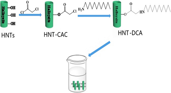
Then, 2.58 g of purified HNTs and 0.01 g of 4-dimethylaminopyridine were added into a three-necked flask (100 mL) containing dichloromethane (30 mL). The equipment was sealed with a rubber stopper and CAC (1.12 g) was slowly injected with a syringe. After 30 min of the reaction time, triethylamine (0.05 g) was added to the solution under an ice bath overnight. Then, the residue was washed and dried to obtain CAC-modified HNTs (HNT-CAC). Subsequently, 3 g of HNT-CAC and dodecylamine (DCA) were dissolved in dimethylformamide (DMF; 30 mL) and reacted at 120°C for 5 h. The product was washed and dried, resulting in DCA-modified HNTs (HNT-DCA). The preparation process is shown in Fig. 1.
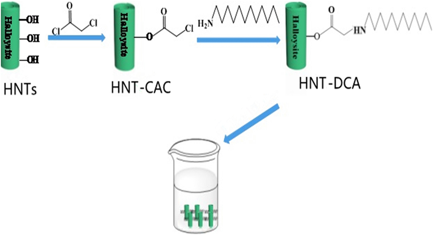
Fig. 1. The preparation process of HNTs modified by DCA.
Preparation of PTFE composites
Polytetrafluoroethylene (purchased from Shanghai 3F New Material Co. Ltd) and HNT-DCA were mixed mechanically in a high-speed stirrer at 3000 rpm for 2 h and subsequently subjected to compression moulding at a pressure of 10 MPa at ambient temperature. Then, the specimens were heated at 375°C for 2 h and allowed to cool at ambient temperature (denoted PTFE/HNT-DCA).
Characterization
The powder X-ray diffraction (XRD) analysis was performed with a Bruker-AXS D8 Advance instrument (Germany) using Cu-Kα radiation, background noise: <0.4 cps; 40 kV, 40 mA; scanning speed 0.1°/s in the range 5–70°2θ. Fourier-transform infrared (FTIR) spectra of the samples were recorded on a Cary 610/670 micro-infrared spectrometer with a resolution of 4 cm–1 in the range 4000–400 cm–1 with KBr pellets containing 0.5% of sample using an attenuated total reflection attachment (Varian, USA). Scanning electron microscopy (SEM) images were recorded on gold-coated samples with an S-4800 microscope (Hitachi Ltd, Japan) at a 10 kV acceleration voltage. The wear scar micrographs were observed with a 700 3D laser scanning microscope (CARL ZEISS, German). The particle-size distribution (dynamic light scattering) was recorded using a Zetasizer nanoparticle size analyser (Malvern, UK).
Measurement of mechanical properties
The tensile strength testing was carried out with a WDW-5 instrument (Shanghai Longhua) on 42.8 mm × 5.9 mm × 0.8 mm test samples at a 50 mm/min tensile speed. Each specimen was tested five times and the mean value was recorded. The thickness of each specimen was calculated from the average of five measurements obtained with a digital micrometer. The data are presented as a mean ± standard deviation. The tribological testing was performed on a MMW-1 ring-on-ring friction and wear tester (Jinan Chenda Ltd Co., China). The contact schematic diagram of the frictional parts follows that of Cheng et al. (Reference Cheng, Chang, Liu and Qin2017).
Results and discussion
Figure 2 shows the FTIR spectra and the XRD traces of HNTs, HNT-CAC and HNT-DCA. The FTIR spectra contain characteristic bands at 3696 and 3621 cm–1 attributed to the stretching vibration of the hydroxyl groups of HNTs. The HNT-CAC showed a carbonyl band at 1642 cm–1, indicating that the CAC reacted with the hydroxyl groups on the surface of the HNTs. In the HNT-DCA, the bending bands of methyl groups appear at 1352 and 1535 cm–1, the vibration modes of the methylene group are located at 2926 and 2850 cm–1 and the vibration of NH appears at 3233 cm–1. These characteristic bands derived from DCA suggest that DCA was successfully grafted onto the surfaces of HNTs. In the XRD patterns, the peaks at 12.3°2θ (001), 20.0°2θ (020) and 24.8°2θ (002) are the three typical characteristic peaks of HNTs (Drits et al., Reference Drits, Sakharov and Hillier2018). After the modification, these peaks were retained and the basal spacing only slightly changed in the three samples. However, the peak intensities became smaller and wider than their counterparts of the original HNTs, which is attributed to the covering of organic compound on the surfaces of HNTs.

Fig. 2. (a) FTIR spectra and (b) XRD patterns of (1) HNTs, (2) HNT-CAC and (3) HNT-DCA.
Figure 3 shows the laser particle-size distribution, ζ-potential and thermogravimetric (TG) curve of HNTs and HNT-DCA. The particle size of pristine HNTs ranges from 142 to 1480 nm (average: 426 nm) (Fig. 3a). The particle-size distribution of HNT-DCA is narrower than that of pristine HNT powder, ranging from 281 to 893 nm (average: 520 nm). This average size is indicative of dispersion of HNTs as single nanotubes (0.5–1.0 µm) after DCA treatment (Pasbakhsh et al., Reference Pasbakhsh, Ismail, Ahmad Fauzi and Bakar2010). Therefore, the dispersibility of the modified HNTs was improved. The ζ-potential of the pristine HNTs in water (1 g/L) is approximately –22 mV, whereas the ζ-potential of HNT-DCA is approximately –17 mV (Fig. 3b). The lower ζ-potential of HNT-DCA compared to pristine HNTs is indicative of the poor colloidal stability of HNT-DCA in water. This variation might be due to the fact that the DCA grafting reduces the free surface charge of HNTs.

Fig. 3. (a) Laser particle-size distribution, (b) ζ-potential, (c) TG curve and (d) DTG curve (D) of (1) HNTs and (2) HNT-DCA.
According to the thermogravimetric (TG) analysis and derivative thermogravimetric (DTG) analysis of HNTs (Fig. 3c,d), the endothermic peak attributed to the evaporation of adsorbed water is absent from treated HNTs, while the corresponding temperature of HNT-DCA shifted to ~150°C. The weight losses of adsorbed water are 0.91% and 2.92%, respectively. In the TG curves of HNTs, there is a large weight loss (~15.9%) from 200°C to 700°C with a DTG signal at 496.4°C, while the two weight-loss events of HNT-DCA are at 445.9°C and 481.3°C. Interestingly, there appear to be two signals within the 400–500°C range, which might be associated with the decomposition of DCA molecules intercalated into the layered structure of HNTs and the structural water removal of HNTs, respectively. The complex behaviour of DCA molecules leads to the emergence of two weak exothermic signals at temperatures between 150.0 and 250.6°C with weight loss of 6.93%, probably caused by the disappearance of the long alkyl chain of DCA molecules and the structural water of HNTs (Yuan et al., Reference Yuan, Tan, Annabi-Bergaya, Yan, Fan, Liu and He2012). Therefore, it is concluded that some DCA molecules are adsorbed onto the surfaces of HNTs.
Figure 4 shows the contact angle, SEM and energy-dispersive spectrometer (EDS) analysis of the HNTs and HNT-DCA. The smaller the contact angle, the more hydrophilic a material becomes. The contact angle of pristine HNT is ~18°, whereas that of the HNT-DCA is ~138°, indicating that the HNTs grafted with DCA are hydrophobic (Fig. 4a). Figure 4c,d shows SEM images of HNTs and HNT-DCA. The particles of pristine HNTs are agglomerated due to the abundant hydroxyl groups on their surfaces. The HNT-DCA particles are less agglomerated than those of HNTs, indicating improved dispersibility of the HNT-DCA. Figure 4e,f shows the EDS spectra of HNTs and HNT-DCA. The HNT-DCA contains 4.8 wt.% C, confirming the surface modification of HNTs with organic molecules.

Fig. 4. Contact angle photos, SEM images and EDS spectra of HNTs (a,c,e) and HNT-DCA (b,d,f).
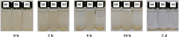
Figure 5 shows digital photographs of the dispersions of HNT-DCA in H2O, EtOH and DMF. The HNT-DCA in H2O and DMF begins settling after 2 h, and precipitates almost completely after 10 h. However, the precipitation of the HNT-DCA in EtOH is not obvious by 10 h, and settling is complete after 2 days, indicating that HNT-DCA has a better dispersibility in EtOH.

Fig. 5. Dispersion photos of HNT-DCA (a) in water, (b) in ethanol and (c) in DMF.
Figure 6 shows the tensile strength, elongation at break, friction coefficient and volume wear rate of HNTs and PTFE/HNT composites. The tensile strength of pure PTFE is 28 MPa, while the tensile strength of PTFE/HNTs filled with 2 wt.% non-modified HNTs is 29 MPa. In addition, the tensile strength of PTFE/HNT-DCA composites is 38 MPa, 35.7% higher than that of pure PTFE, highlighting the reinforcing effect of HNTs after modification. This should be attributed to the fact that the HNT-DCA has better dispersibility in a PTFE matrix, thus improving the tensile strength of PTFE. In addition, due to the introduction of DCA as a long-chain molecule on the surfaces of HNTs, the pulling effect of HNTs on the PTFE matrix is facilitated, which improves tensile strength. The elongation at break of pure PTFE is 488% and that of the PTFE composites filled with 2 wt.% of non-modified HNTs is 375%, slightly lower than that of pure PTFE (Fig. 6b). The elongation at break of the PTFE composite filled with HNT-DCA reaches 520%, which is 16% and 30% higher than those of PTFE composites filled with non-modified HNTs and pure PTFE, respectively. Due to the substantial improvement in the dispersion of HNTs by virtue of the strong interfacial interactions, the PTFE/HNTs showed excellent mechanical processability. These modifications increased the interactions between HNTs and PTFE and the degree of dispersion of HNTs in the PTFE matrix, consequently leading to improved tensile strength and tensile modulus. The improvements in the mechanical properties of the PTFE nanocomposites are attributed to the presence of the reinforcing HNT filler, to which load is efficiently transferred from the polymers. The presence of HNTs nanofillers causes concentration of stress at the filler surface.

Fig. 6. (a) Tensile stress, (b) elongation of break, (c) friction coefficient and (d) volume wear rate of PTFE/HNT composites: (1) PTFE, (2) PTFE/2%HNT and (3) PTFE/2%HNT-DCA.
The friction coefficient of pure PTFE is stabilized at ~0.15 after the running-in period, and the steady friction of the PTFE composites filled with non-modified HNTs approaches that of pure PTFE over time (Fig. 6c). However, the friction coefficient of PTFE/HNT-DCA is constant at ~0.18 over time, slightly higher than that of pure PTFE. This is because the PTFE composites filled with HNTs may modify the composition of the transfer film formed on the counterface. The pure PTFE has a wear volume rate of 0.55 cm3/h under a load of 200 N, a rotation speed of 200 rpm and a friction time of 1 h (Fig. 6d). The wear volume rate of the PTFE composites filled with non-modified HNTs is 2.2 times greater than that of pure PTFE. Surprisingly, the wear volume rate of the PTFE composites filled with HNT-DCA is up to 0.009 cm3/h, 60 times lower than that of pure PTFE. The HNT-DCA filler exhibits excellent wear resistance because the HNT-DCA has better dispersibility in a PTFE matrix and the long-chain structure of DCA on the surface of HNTs has a more pronounced pulling effect on PTFE molecules. These effects may reduce the turnover rate of the transfer film on the counterface. The compatibility and mechanical strength of HNTs may render the transfer effect of the stress more efficient, thus preventing damage occurring over a large area under the operating load. PTFE crystals with a hexagonal structure and a thickness of 20–50 nm consisting of macromolecular chains have a ribbon-like structure and a smooth surface. Due to the outer diameter of HNTs being up to 15–100 nm, their size is the same order of magnitude as the dimensions of PTFE single crystals. Hence, HNTs are prone to intertwine with crystals of PTFE. Because of their stronger mechanical properties and greater aspect ratio than those of other fibres, the HNTs are demonstrated to reinforce PTFE significantly, thus preventing the crystal structure of PTFE from being destroyed over the duration of the wear test. The PTFE crystals may be drawn out from a PTFE surface through shearing. Therefore, the HNTs may effectively inhibit this drawing-out and thus significantly improve the wear resistance of PTFE.
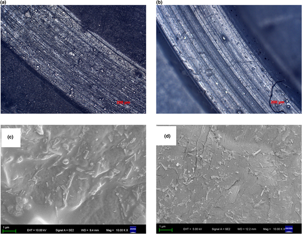
The worn scar surface of PTFE without HNT filling is rougher and contains more furrows, indicating that the worn mechanism of PTFE without HNT filling is subjected to adhesive wear and fatigue wear (Fig. 7a,b). After filling with modified HNTs, the furrows gradually decrease, indicating that abrasive wear and adhesive wear are dominant. The reason for this is attributed to HNTs with good dispersion in a PTFE matrix potentially being able to reduce the stretching of PTFE crystals and to enhance the tensile strength of PTFE (Wang & Yan, Reference Wang and Yan2006). As far as the dispersion in PTFE is concerned, there is a distinct difference between PTFE/HNTs and PTFE/HNT-DCA (Fig. 7b). This corroborates the good dispersion of HNTs in PTFE/HNT-DCA.
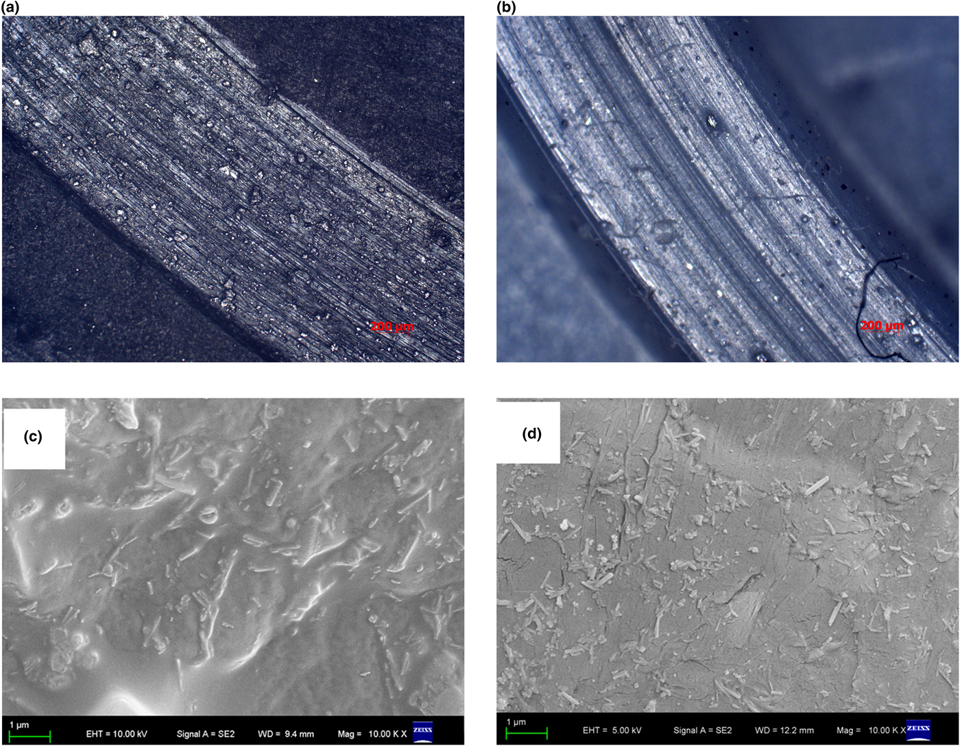
Fig. 7. Laser microscope images of the worn surfaces of (a) PTFE and (b) PTFE/HNT-DCA; fracture photos of (c) PTFE/HNTs and (d) PTFE/HNT-DCA.
Conclusion
This work exploited the abundant hydroxyl groups of HNTs by inducing CAC and subsequently grafting the hydrophobic molecule DCA, forming HNT-DCA. The DCA was successfully grafted onto the surfaces of HNTs nanotube, the hydrophobicity of the modified HNTs increased significantly and the dispersibility in the lower polar solvent ethanol was enhanced significantly. As a promising application of HNTs, a composite of DCA-grafted HNT/PTFE with 2 wt.% HNTs was prepared. The mechanical and tribological properties of the modified HNT-filled PTFE were studied. The tensile strength and the elongation at break of the modified HNT-filled PTFE composites were 35.7% and 16.0% higher than those of PTFE without filling HNTs, and the wear rate was only 3.9% of the wear rate of PTFE without HNTs filling, while the friction coefficient was closer to that of pure PTFE.
Acknowledgements
This work was funded by the Talent Introduction Fund of Yangzhou University (2012), Zhenjiang High Technology Research Institute of Yangzhou University (2017), Key Research Project-Industry Foresight and General Key Technology of Yangzhou (YZ2015020), Innovative Talent Program of Green Yang Golden Phoenix (yzlyjfjh2015CX073), Yangzhou Social Development Project (YZ2016072), Jiangsu Province Six Talent Peaks Project (2014-XCL-013) and Jiangsu Industrial-academic-research Prospective Joint Project (BY2016069-02). The authors also acknowledge the project funded by the Priority Academic Program Development of Jiangsu Higher Education Institutions and Top-notch Academic Programs Project of Jiangsu Higher Education Institutions (PPZY2015B112). The data presented in this paper originated from the Test Center of Yangzhou University.