


Sericite mica, a layered aluminium potassium silicate (KAl2[AlSi3O10](OH)2), is a widespread clay mineral (Zhang et al., Reference Zhang, Fu, Li, Wu, Li, Ji and Yang2005) composed of two Si tetrahedral sheets with a central Al octahedral sheet. Sericite mica has excellent heat resistance, electrical insulation and chemical resistance properties (Shih & Shen, Reference Shih and Shen2009; Nie et al., Reference Nie, Wei, Lu and Liu2013), and its special nanolayer structure can not only prevent the infiltration, diffusion and transmission of the air, moisture and corrosive media, but may also play a protective role in polymer composites (Arias et al., Reference Arias, Rosa and Marques2019; Xiao et al., Reference Xiao, Li, Zeng, Lang, Xiang and Lin2021). Therefore, sericite mica as an important functional filler had been used widely in polymer composites such as polyimide (Zhang et al., Reference Zhang, Li, Lai, You and Ou2016), polyamide (Uno et al., Reference Uno, Tamura, Yamada, Umeyama, Hatta and Moriyoshi2009), poly(arylether ketone) (Gan et al., Reference Gan, Lu, Song and Wang2001) and epoxy (Tamura et al., Reference Tamura, Yokoyama, Pascua and Yamada2008). However, sericite mica displays a poor dispersion capacity in polymer matrices due to its ease of agglomeration and poor compatibility with the polymer matrix resulting from its surface hydrophilicity, which greatly limits its application in polymers. Therefore, it was necessary to modify sericite mica to increase its dispersion in polymer matrices and its compatibility with polymers so as to improve its performance and use value (Hokkaido, Reference Hokkaido1994; Uno et al., Reference Uno, Tamura, Yamada, Umeyama, Hatta and Moriyoshi2009).
At present, the modification of sericite mica mainly involves surface graft modification by a coupling agent and intercalation modification by an organic ammonium cation (Yang et al., Reference Yang, Zhu, Yin, Wang and Qi1999; Gao et al., Reference Gao, Yuan, Wang, Guan, Zhang, Jing and Mao2007; Yu, Reference Yu2007; Jia et al., Reference Jia, Chen and Zhang2013; Liang et al., Reference Liang, Ding, Wang, Liang and Wang2013; Ding et al., Reference Ding, Wang, Liang and Qin2014). In addition, sericite mica particles have been covered with TiO2 inorganic particles (Yun et al., Reference Yun, Han, Lee and Choi2002; Ren et al., Reference Ren, Yin, Wang, Jiang and Wada2007) and caesium oxide doped with synthetic calcium/mica compound silica (El-Toni et al., Reference El-Toni, Yin and Sato2006), as well as using the multi-channel encapsulation method and so on (Skale et al., Reference Skale, Doleček and Slemnik2008). The modification with coupling agents improved some of the polymer's thermal and mechanical properties, but these properties were still not ideal because the compatibility between the inorganic particles of sericite mica and the polymers remained poor (Bose et al., Reference Bose, Raghu and Mahanwar2006; Yang et al., Reference Yang, Yu, Liu and Wang2008). In addition, although the modification of sericite mica with the intercalation of an organic ammonium cation facilitated its dispersion in the polymer matrix for low clay loadings and greatly improved the thermal and mechanical properties of the polymer composites (Chang et al., Reference Chang, Mun and Kim2007; Li et al., Reference Li, Chen, Wu and Shen2011; Zhang et al., Reference Zhang, Li, Lai and Ou2015; Fu et al., Reference Fu, Wang, Wang, Gao and Xiong2019; Zhao et al., Reference Zhao, Xu, Song, Chen and Liu2019), the problem of poor dispersion remained at greater contents of sericite mica. Therefore, in order to prepare more efficient polymer composites, it was necessary to modify sericite mica through the combination of intercalation and surface modification. In a typical intercalation process, the sericite mica is first activated at high temperatures. Subsequently, a modified sericite mica with enlarged interlayer spacing is obtained by reaction with nitric acid and a series of interlayer cation-exchange reactions that do not affect the surface modification of sericite mica (Li et al., Reference Li, Chen, Wu and Shen2011; Zhang et al., Reference Zhang, Li, Lai, You and Ou2016). The hydroxyl groups of the mica react with a variety of coupling agents (Bose & Mahanwar, Reference Bose and Mahanwar2010; Ismail et al., Reference Ismail, Hamid and Ishak2012; Ismail et al., Reference Ismail, Ishak and Hamid2014). Activation through heating at high temperatures is the critical step before sericite mica can be modified by an organic ammonium cation through interlayer cation exchange. High-temperature activation affects the number of hydroxyl groups of sericite mica and directly controls the surface grafting modification. Therefore, the main targets of this study were an investigation of the effects of various activation temperatures on the sericite surface and a determination of the optimal activation temperature. Finally, cetyltrimethylammonium bromide (CTAB) and 3-aminopropyltriethoxysilane (KH550)-modified sericite mica were successfully prepared and characterized, thus contributing to an improvement of the thermal and mechanical properties of the polymer composites. A flow diagram for the preparation of CTAB and KH550-modified sericite mica is shown as Scheme 1.
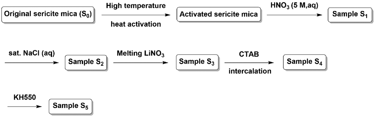
Scheme 1. Flow diagram for the preparation of CTAB and KH550-modified sericite mica.
Experimental
Materials
Original sericite mica (2500 mesh, Chenxing Industry Co., Ltd, Shijiazhuang, China) was washed with deionized water to remove impurities and dried for 24 h in vacuum at 100°C. The KH550 was procured from Sinopharm Chemical Reagent Co., Ltd (China) and the CTAB was supplied by the China National Medicine Group. Other reagents were commercially available and used without further purification.
High-temperature activation and surface grafting modification of sericite mica
In order to investigate the effect of activation temperature on the surface modification of sericite mica so as to determine the optimal activation temperature, the following experiments were carried out:
(1) The original sericite mica (S0) was thermally activated at 600°C, 700°C and 800°C for 1 h and then cooled to room temperature. The activated sericite mica powders obtained were named S600, S700 and S800, respectively.
(2) A certain amount of original sericite mica and the above activated sericite mica powder were placed into a three-necked flask and deionized water (15 mL) and ethanol (15 mL) were added. Then, the sericite mica was dispersed evenly by magnetic stirring, and the pH was adjusted to ~3–4 by adding acetic acid. Subsequently, KH550 (10 wt.% of the activated sericite mica powder) was added dropwise at room temperature. The mixture was stirred continually for 12 h and then was heated to 70°C for 3 h and cooled to room temperature. The reaction mixture was filtered and the filter cake was washed with deionized water and ethanol three times and dried in vacuum at 60°C for 5 h. The surface-modified sericite mica powders obtained were labelled KH550-S0, KH550-S600, KH550-S700 and KH550-S800.
Preparation of CTAB and KH550-modified sericite mica
The CTAB and KH550-modified sericite mica were prepared from the activated sericite mica obtained at the optimal temperature described above according to the multistep reaction (Scheme 1) as follows:
(1) The activated sericite mica (25 g) obtained under the optimal temperature was leached with 5 M HNO3 solution under stirring for 5 h at 95°C and cooled to room temperature. The reaction solution was filtered and the filter cake was washed with deionized water several times and dried in vacuum at 80°C for 12 h. The resulting acidified sericite mica sample was labelled S1.
(2) The sample S1 (20 g) was reacted with saturated NaCl solution under stirring for 12 h at 120°C and cooled to room temperature. The solution was filtered and the filter cake was washed with deionized water several times and dried in vacuum at 80°C for 12 h. The resulting sericite mica sample was labelled S2.
(3) A mixture of sample S2 (10 g) and LiNO3 powder (200 g) was mixed thoroughly for 0.5 h then heated to 350°C in a furnace for 48 h and cooled to room temperature. Then, the mixture was added to deionized water (800 mL) and filtered, and the filter cake was washed with deionized water several times and dried in vacuum at 80°C for 12 h. The resulting sericite mica sample had a cation-exchange capacity of 60 cmol+ kg–1 and was labelled S3.
(4) A total of 5 g of S3 was dispersed evenly in 600 mL of deionized water, then the intercalating agent CTAB (16.4 g, 45.0 mmol) was added. The mixture was heated at 150°C for 3 days under vigorous stirring, cooled to room temperature and filtered. The filter cake was washed repeatedly with deionized water to remove excess CTAB, and the filter cake was dried in vacuum at 80°C for 12 h. The sericite mica sample obtained was labelled S4.
(5) A total of 3 g of sample S4 was dispersed in deionized water (15 mL) and ethanol (15 mL). The pH was adjusted to ~3–4 with acetic acid, and KH550 (0.3 g) was added dropwise at room temperature. The mixture remained under stirring for 12 h, then heated at 70°C for 3 h, cooled to room temperature and filtered. The filter cake was washed repeatedly with deionized water and dried in vacuum at 60°C for 5 h. The modified sericite mica sample obtained was labelled S5.
Characterization
Fourier-transform infrared (FTIR) spectra were recorded on a Nicolet MAGNA-IR 750 spectrometer using KBr discs or thin films. An X-ray diffraction (XRD) study was performed on a Rigaku D/Max 2550 instrument at 40 kV and 250 mA with Cu-Kα radiation. The experiments were performed in the range of ~5–75°2θ with a step size of 0.02° at a scanning rate of 3° min–1. A scanning electron microscopy (SEM) study was performed with an FEI Quanta FEG 250 instrument on gold-coated samples. X-ray photoelectron spectroscopy (XPS) analysis was performed using a K-Alpha 1063 spectrometer with an Al-K X-ray source to determine the accurate binding energies of elements. Thermogravimetric analysis (TGA) curves were obtained on a NETZSCH STA 449C thermal analyser on samples heated in an alumina crucible at a rate of 10°C min–1 from 50 to 900°C in an argon atmosphere. The specific surface area of the modified sericite mica was determined by N2 adsorption–desorption isotherms at –196°C with a multistation specific surface area and porosity analyser (Model ASAP 2460; Micromeritics, USA). The samples were degassed at 70°C for 12 h prior to analysis.
Results and discussion
The effects of various activation temperatures on the surface modification of sericite mica
FTIR spectra of the original and activated sericite mica
Figure 1 shows the FTIR spectra of the original and activated sericite mica. The absorption bands at ~472 and 800 cm–1 are assigned to Al–O and Si–O stretching and bending, respectively. The band near 1024 cm–1 is assigned to Si–O–Si stretching (Zhang et al., Reference Zhang, Li, Lai, You and Ou2016). The two absorption bands at ~3445 and 3622 cm–1 were assigned to the –OH stretching vibration of adsorbed water and the stretching of the lattice OH of sericite mica, respectively. After the original mica was activated at 600°C, 700°C and 800°C, the structure did not seem to be affected, but the intensity of the absorption band near 3622 cm–1 decreased gradually with the increase in the activation temperature due to dehydroxylation. The band at ~3622 cm–1 of S800 almost disappeared, indicating almost total dehydroxylation. However, the absorption band at 3440 cm–1 did not disappear, indicating that there was still adsorbed water present.
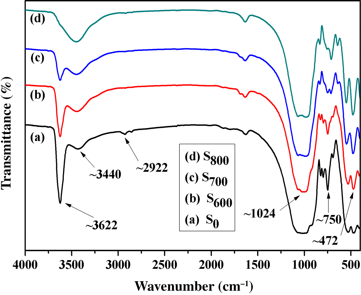
Fig. 1. FTIR spectra of (a) S0, (b) S600, (c) S700 and (d) S800.
XRD of the original and activated sericite mica
The XRD traces of S0, S600, S700 and S800 are shown in Fig. 2. Two major sharp basal diffraction peaks at 8.86 and 26.9°2θ (corresponding to d spacings of 1.00 and 0.33 nm, respectively) dominate the XRD traces of S600, S700 and S800. The XRD traces of S600 and S700 are comparable to those of S0. However, the intensity of the 001 diffraction peak at 8.86°2θ decreased significantly compared to those of S0, S600 and S700, while the intensity of the diffraction peak at 26.9°2θ increased significantly. The XRD results suggest that the temperature of 800°C might be too high for the activation of sericite mica.
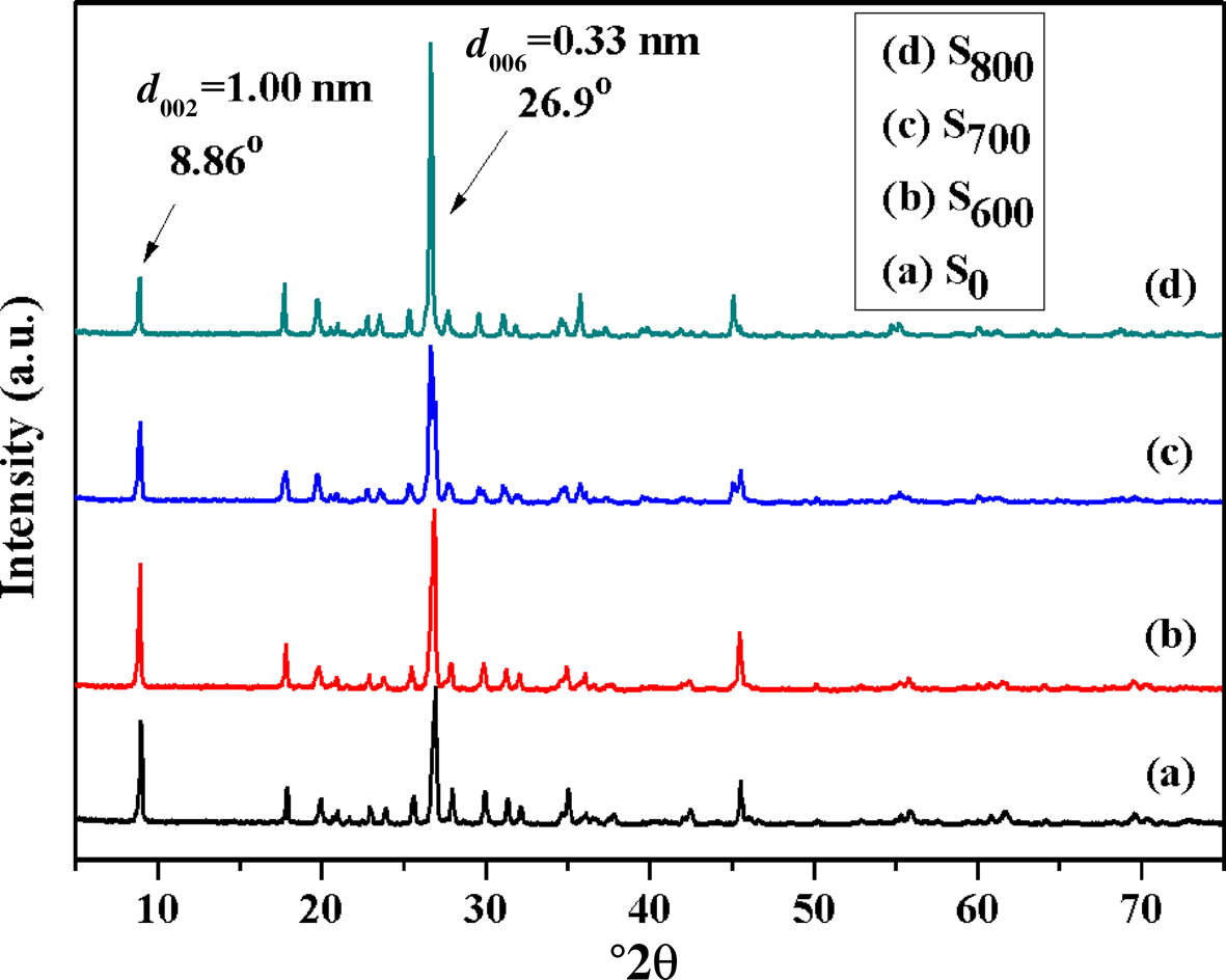
Fig. 2. XRD traces of (a) S0, (b) S600, (c) S700 and (d) S800.
SEM study of the original and activated sericite mica
Figure 3 shows SEM images of the original and activated sericite mica. The particles of S0 are tightly stacked and the crystal surface is flat with a smooth morphology. After activation at 600°C, the sericite particles (S600) became looser, stacking was destroyed and the particle edges were blurred. After heating at 700°C, the S700 particles became more disordered and their edges displayed cracks. After heating at 800°C, the surface of S800 particles became more blurred and the particle edges grew curved, which indicated partial structural disruption, in accord with the XRD results.
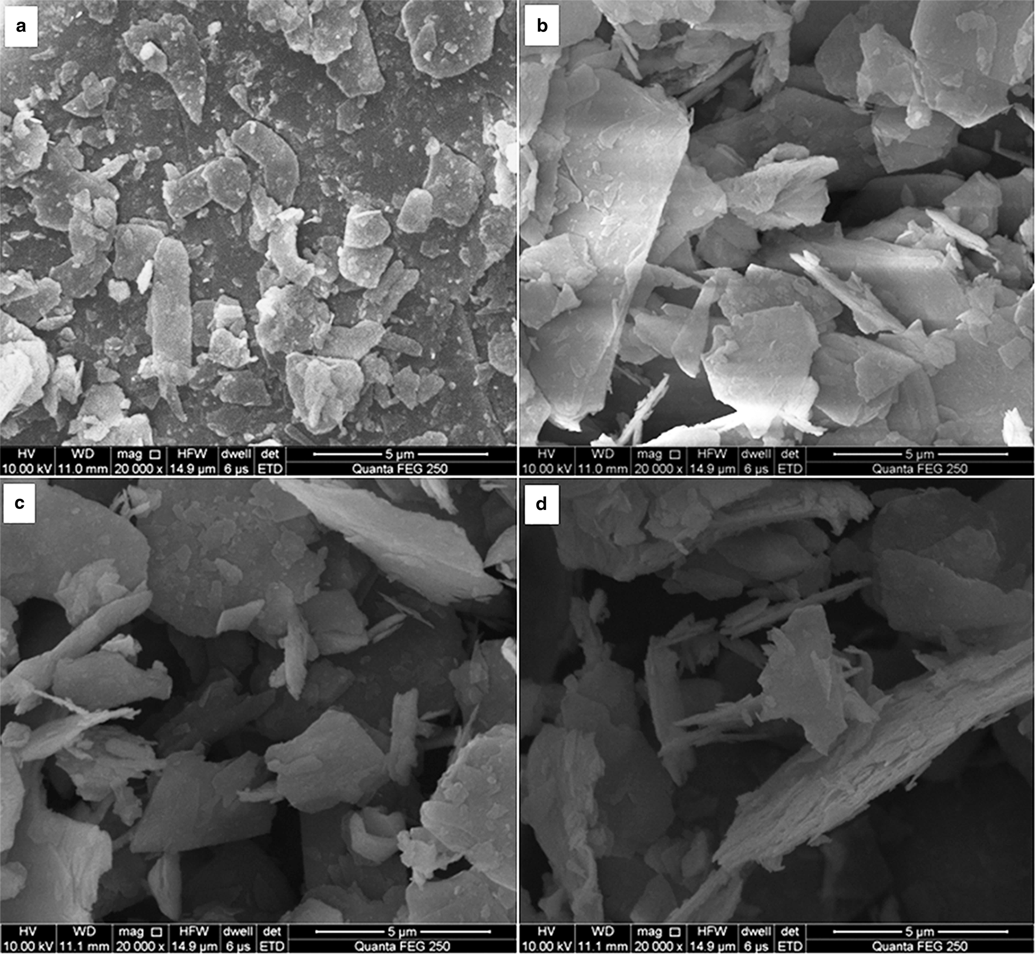
Fig. 3. SEM images of (a) S0, (b) S600, (c) S700 and (d) S800.
The aforementioned results suggest that the activation temperature for sericite mica should not exceed 700°C. In order to select the optimal thermal activation temperature, the effects of KH550 on the surface modification of S600 and S700 were further investigated.
FTIR spectra of S0, KH550-S0, KH550-S600 and KH550-S700
The FTIR spectra of S0, KH550-S0, KH550-S600 and KH550-S700 are shown in Fig. 4. Comparing Figs 1 and 4, modification of the activated sericite mica with KH550 reduced significantly the intensity of the band at 3622 cm–1, whereas the band at 1024 cm–1 became sharper compared to S0, suggesting that KH550 reacted with the –OH of sericite mica and that KH550 was grafted successfully onto the sericite surface. The intensity of the –OH stretching band at 3622 cm–1 in samples KH550-S600 and KH550-S700 decreased compared to that of KH550-S0, probably due to the greater surface grafting rate of KH550 on S600 and S700 compared to S0. The grafting rate of KH550-S700 was greater due to the increased dehydroxylation caused by the greater activation temperature, and it was possible to reduce the grafting rate of KH550 on the sericite mica surface. In addition, previous work has shown that the specific surface area of the sericite mica increases after activation at high temperature, and the greater the activation temperature, the greater the specific surface area (Lalhmunsiama et al., Reference Lalhmunsiama, Tiwari and Lee2015), which is in accordance with the present work. Furthermore, the FTIR spectra of S0, KH550-S0, KH550-S600 and KH550-S700 showed few differences (Fig. 4).
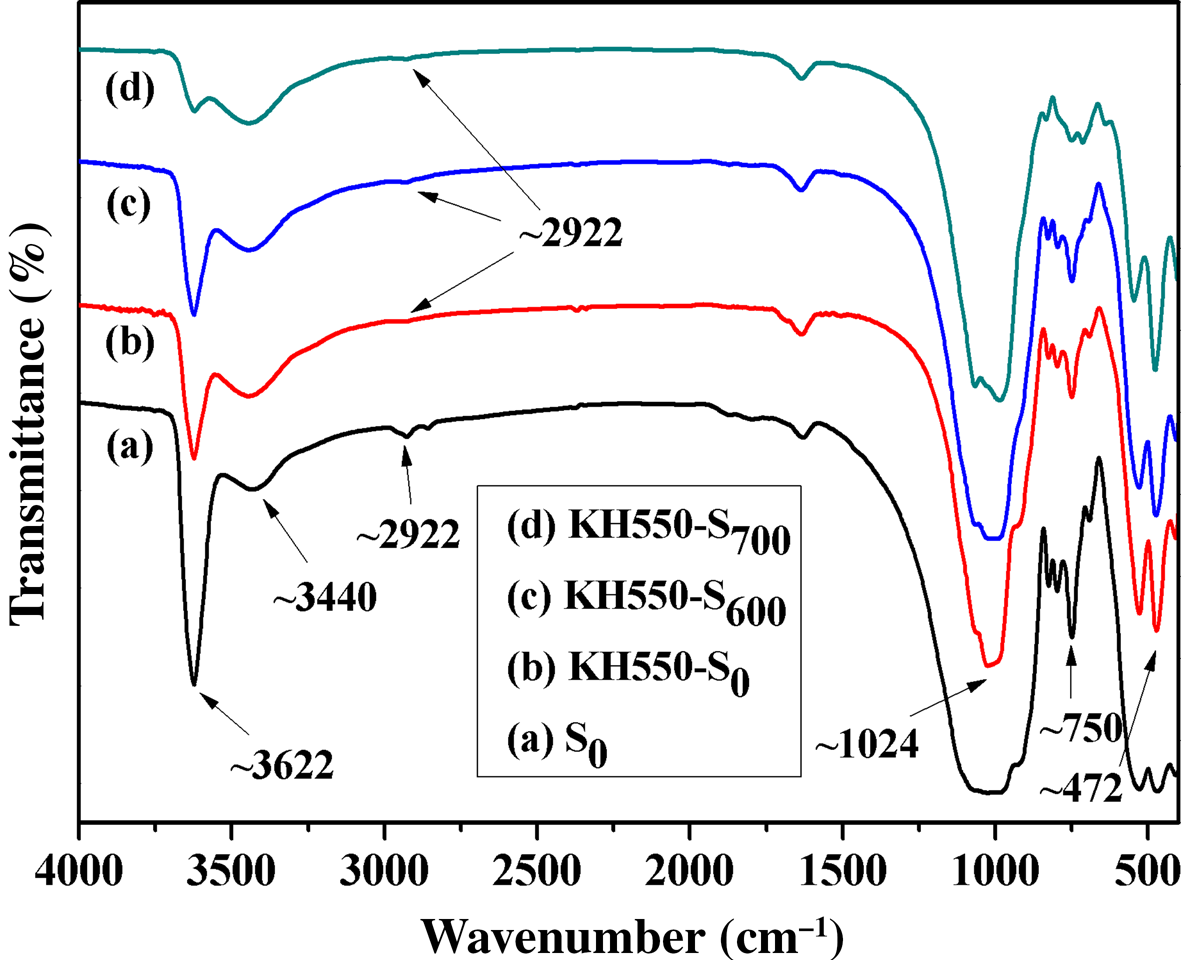
Fig. 4. FTIR spectra of (a) S0, (b) KH550-S0, (c) KH550-S600 and (d) KH550-S700.
After modification of activated sericite mica by KH550, a new weak band appeared at ~2922 cm–1, assigned to –CH2– from KH550. The FTIR spectrum of S0 also contained a weak absorption band near 2922 cm–1, assigned to organic agents added during the beneficiation process. The spectra of high-temperature-activated sericite mica did not contain the absorption band at ~2922 cm–1 (Fig. 1), indicating that KH550 was successfully grafted onto the sericite mica surface. In addition, the spectra of sericite modified by KH550 did not display a C–N absorption band (Fig. 4) due to the low additive amount of KH550 and the weak absorption band of –NH2.
After modification of S0, S600 and S700 by KH550, the absorption bands of sericite mica at 472, 750 and 1024 cm–1 were not affected, suggesting that the structure of sericite mica was not affected (Fig. 4). Similarly, the intensity of the absorption band of adsorbed water at 3440 cm–1 was not affected, indicating that the surface modification of sericite mica with KH550 did not affect water adsorption. In brief, KH550 was grafted onto the surface of sericite mica by chemical bonding and did not affect the structure of sericite mica.
XRD study of S0, KH550-S0, KH550-S600 and KH550-S700
The XRD traces of S0, KH550-S0, KH550-S600 and KH550-S700 are shown in Fig. 5. The diffraction maxima of KH550-S0, KH550-S600 and KH550-S700 did not change significantly after modification with KH550 (cf. Figs 2 & 5). Therefore, the surface of S0 could still be chemically modified with KH550 after high-temperature activation. In addition, after modification of the original and activated sericite mica by KH550, the structure of sericite mica did not change, but the KH550 was grafted onto the surface of sericite mica. However, the optimal activation temperature was not identified using XRD analysis.
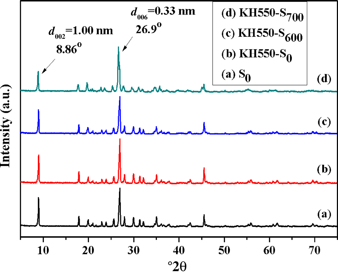
Fig. 5. XRD traces of (a) S0, (b) KH550-S0, (c) KH550-S600 and (d) KH550-S700.
SEM images of S0, KH550-S0, KH550-S600 and KH550-S700
The surface morphology of the sericite mica powder was used as a proxy for determining the optimum activation temperature. The SEM images of S0, KH550-S0, KH550-S600 and KH550-S700 are shown in Fig. 6. After the original or activated sericite mica was modified by KH550, its surface became blurred (Fig. 6). The surface of KH550-S700 became more blurry, and its grain-stacking state was looser than that of KH550-S600, indicating that 700°C was the optimal activation temperature.
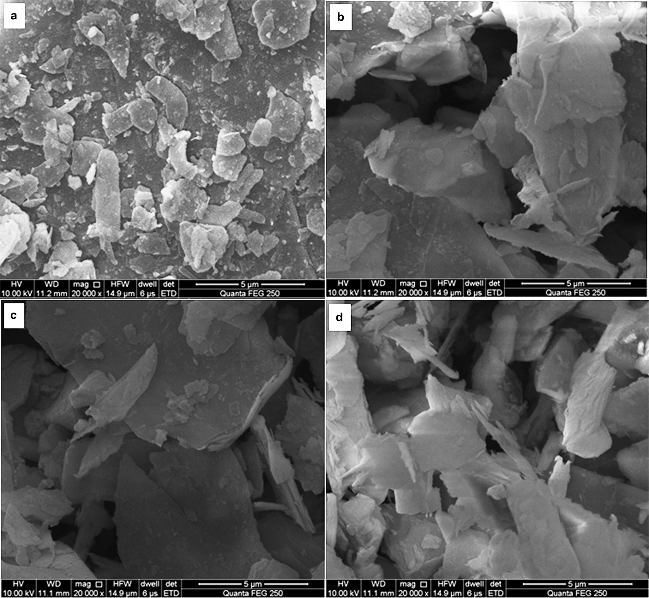
Fig. 6. SEM images of (a) S0, (b) KH550-S0, (c) KH550-S600 and (d) KH550-S700.
TGA analysis of S0, S600, S700, KH550-S0, KH550-S600 and KH550-S700
Figure 7 shows the TGA curves of S0, S600, S700, KH550-S0, KH550-S600 and KH550-S700. S0, S600 and S700 display a mass loss event at <200°C due to evaporation of the adsorbed water, a second mass loss at ~200–600°C due to the removal of tightly bound water and a third mass loss at ~600–900°C due to dehydroxylation (Heller-Kallai, Reference Heller-Kallai2006; Samakande et al., Reference Samakande, Hartmann, Cloete and Sanderson2007). The second event is more pronounced in S0. Thermal degradation of KH550 grafted onto the surface of sericite mica also occurred at ~200–600°C; hence, the mass loss of KH550-S0 at ~200–600°C is due to the decomposition of KH550 and release of tightly bound water. The mass loss rate of KH550-S0 at ~200–600°C was lower than that of S0, probably because the KH550 was tightly bound on the surface of the sericite layers and so physically blocked the release of the adsorbed water. In addition, KH550-S700 displayed a greater thermal mass loss rate than those of KH550-S600 and KH550-S0 (Fig. 7), probably due to the greater specific surface area and grafting rate of KH550 compared to those of KH550-S600 and KH550-S0 (Lalhmunsiama et al., Reference Lalhmunsiama, Tiwari and Lee2015). Hence, the optimal activation temperature for sericite mica was 700°C.
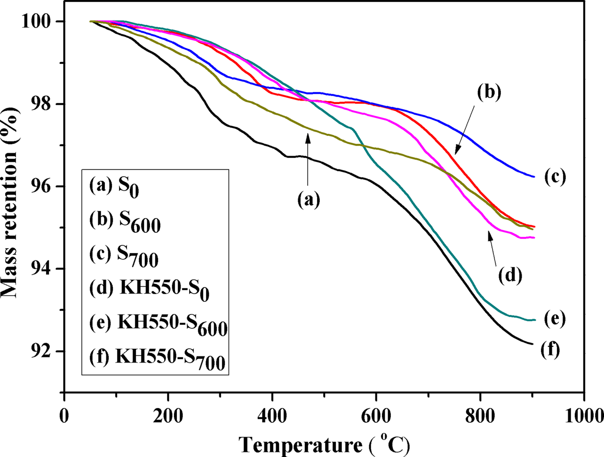
Fig. 7. TGA curves of (a) S0, (b) S600, (c) S700, (d) KH550-S0, (e) KH550-S600 and (f) KH550-S700.
Characterization of CTAB and KH550-modified sericite mica
FTIR spectra of S0, S4 and S5
The original sericite mica was activated at 700°C and subsequently modified with CTAB and KH550 through multistep reaction conditions. Figure 8 shows the FTIR spectra of S0, S4 and S5. After modification with CTAB, new bands appeared at 2922 and 2852 cm–1, assigned to –CH2– and –CH3, respectively, and at 1414 and 1474 cm–1, assigned to quaternary ammonium salt, indicating that CTA+ was successfully intercalated into the sericite mica. The FTIR spectrum of S5 was similar to that of S4 because the characteristic bands of the organic groups of KH550 grafted onto the surface of sericite mica were similar to those of CTA+.
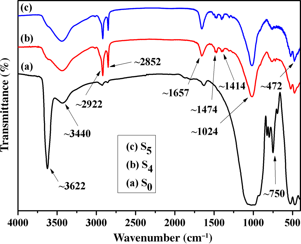
Fig. 8. FTIR spectra of (a) S0, (b) S4 and (c) S5.
XRD study of S0, S3, S4 and S5
The XRD traces of S0, S3, S4 and S5 are shown in Fig. 9. After the activated sericite mica S700 was treated with LiNO3, the d 002 of S3 increased to 1.22 nm, which was beneficial for the intercalated reaction of the organic ammonium cation in the next step (Yu et al., Reference Yu, Zhao, Gao, Zhang and Wu2006). After S3 was treated with CTAB, the d 002 of the S4 obtained increased further to 2.78 nm. Finally, after treatment of S4 with KH550, the d 002 increased to 3.22 nm, suggesting that KH550 not only modified the surface of the sericite mica, but was also intercalated in the interlayer. This is because the terminal amino group of KH550 was protonized under acidic conditions, entering the interlayer of sericite mica through ion exchange (Lai et al., Reference Lai, Li, Yang and Yang2014). The observed d-spacings were greater than those reported in previous work under the same modification conditions or using other intercalation agents (Theng, Reference Theng2012; Ding et al., Reference Ding, Wang, Liang and Qin2014; Zawrah et al., Reference Zawrah, Khattab, Saad and Gado2014; Zhang et al., Reference Zhang, Li, Lai and Ou2015; Siregar et al., Reference Siregar, Wijaya, Kunarti, Syoufian and Suyanta2018). In addition, there is limited previous work on the comprehensive treatment of sericite mica combining intercalation and surface modification.
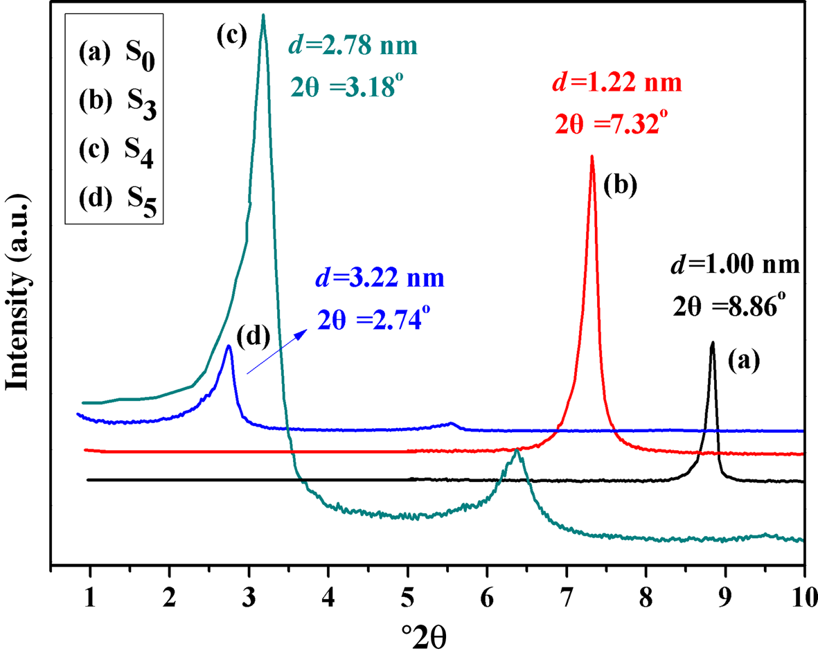
Fig. 9. XRD traces of (a) S0, (b) S3, (c) S4 and (d) S5.
XPS spectra of S4 and S5
X-ray photoelectron spectroscopy was employed to investigate the changes in N1s before and after modification of S4 with KH550. The XPS spectra of S4 and S5 and their high-resolution spectra of the N1s of S4 and S5 are depicted in Fig. 10. In the XPS spectra of S4 and S5, the N atom percentages increased from 1.93% (S4) to 2.76% (S5), indicating successful introduction of KH550 (Fig. 10a). To understand the synthesis principle further, deconvolution of high-resolution spectra (N1s) was performed. After S4 reacted with KH550, a new shoulder peak appeared in the high-resolution spectra of the N1s of S5 (Fig. 10b). Three peaks appeared in the N1s of S5 (Fig. 10c), assigned to –NH2 (399.4 eV), C–N+ (401.2 eV) and C–N (402.4 eV). These data indicate that KH550 successfully grafted by chemical reaction with oxygen groups on the S4 surface, and the new shoulder peak of the N1s of S5 might be attributed to the peak of –NH2 from KH550.
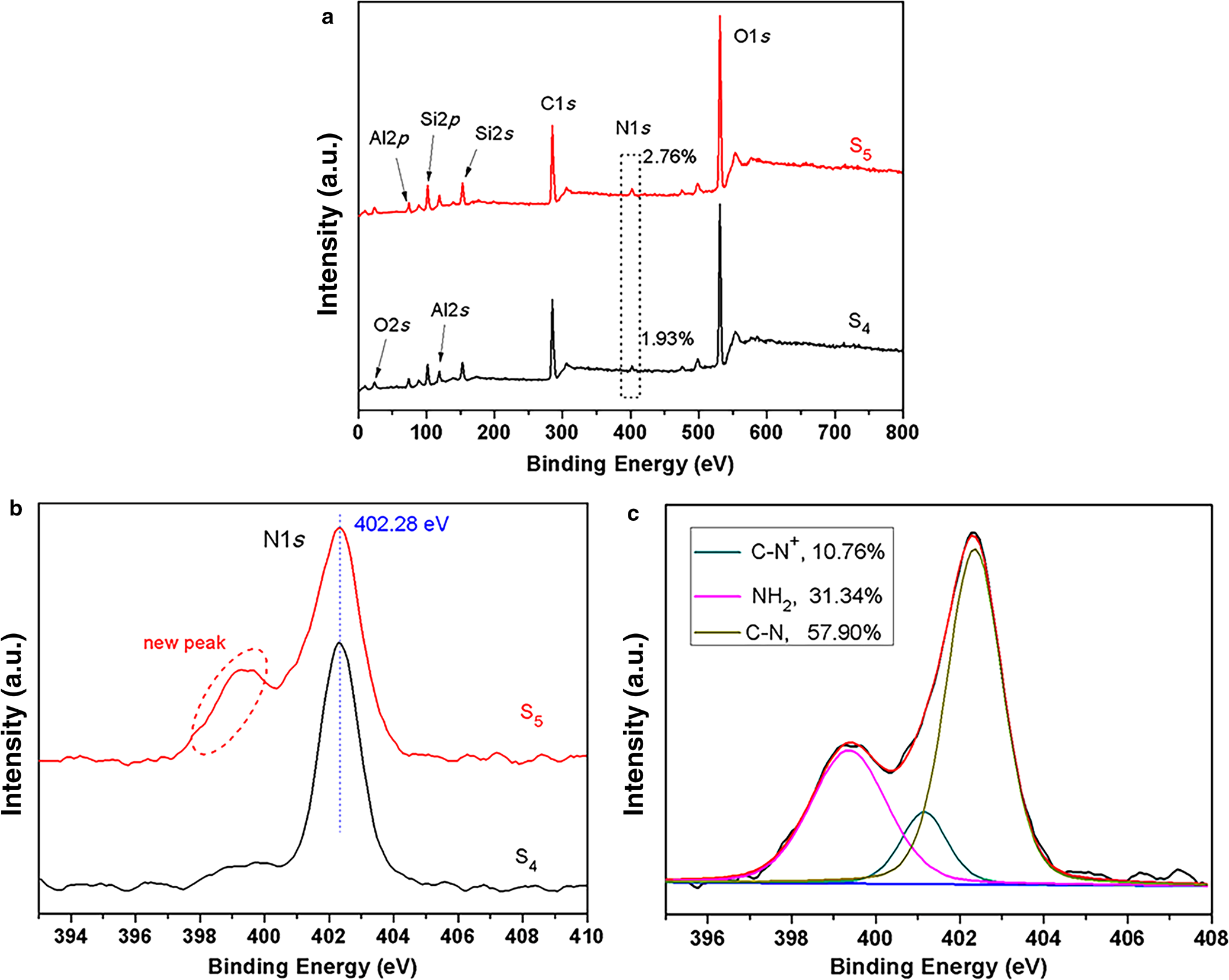
Fig. 10. (a) XPS survey spectra of S4 and S5 and high-resolution spectra of the N1s of (b) S4 and S5 and (c) S5.
SEM images of S4 and S5
The surface morphology of S4 and S5 was studied using SEM (Fig. 11). The mica particles in S0 are smaller and blockier compared to those of S4 and S5 (Figs 6a and 11). Although the sizes of S4 and S5 particles were slightly greater than that of their S0 counterpart, the particles formed thin layers, suggesting that the structure of sericite mica changed due to the exchange reaction between CTAB and the interlayer cations. The particles in S4 were attached close to each other and have a clear surface, while the particles in S5 were more loosely compacted than their counterparts in S4, and the thin sheet surface and edges of the S5 particles were more blurred, further demonstrating that KH550 had been grafted successfully onto the surface of S4 (Fig. 11).
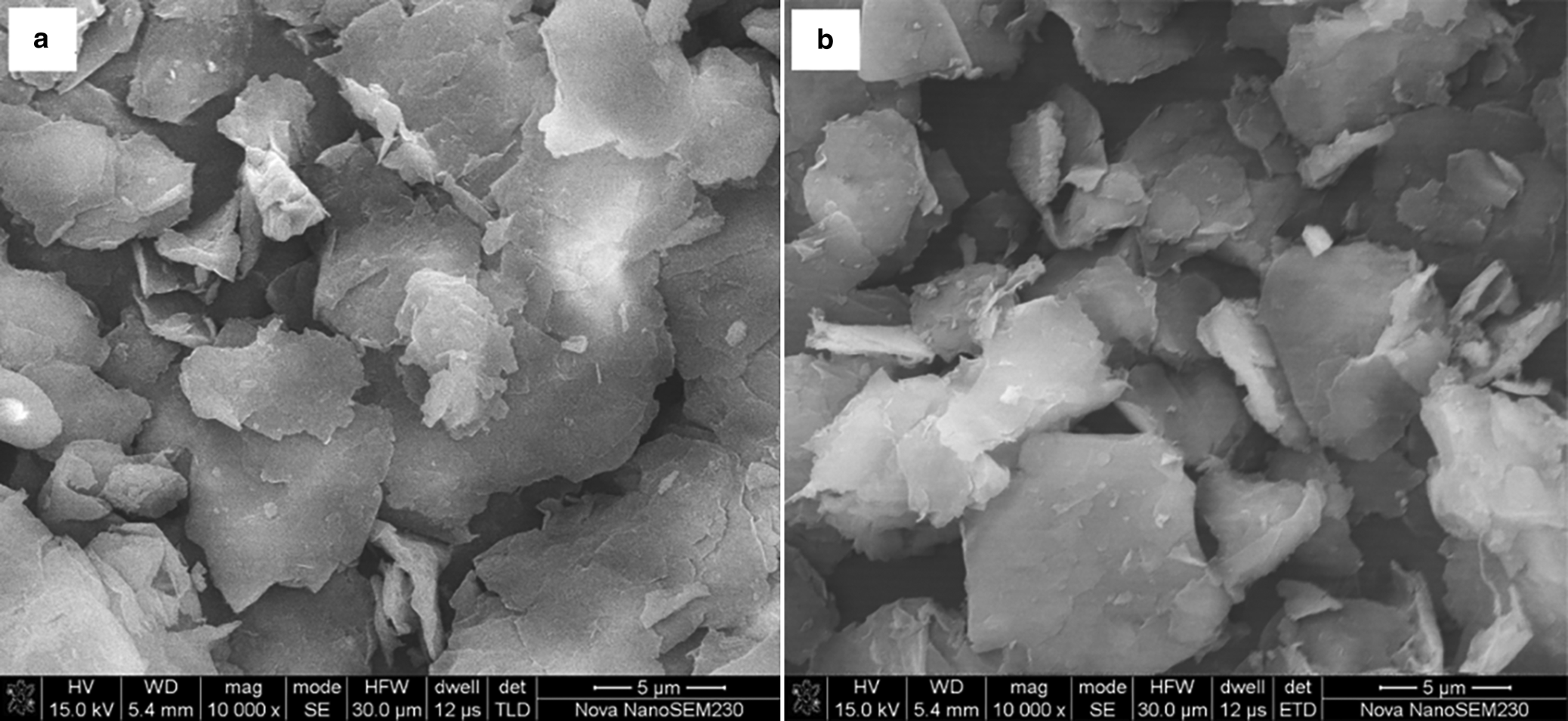
Fig. 11. SEM images of (a) S4 and (b) S5.
Brunauer–Emmett–Teller analysis of S0, S4 and S5
The nitrogen adsorption isotherms of S0, S4 and S5 are shown in Fig. 12. The isotherms are type IV with a H3 hysteresis loop, suggesting the presence of mesopores (Lalhmunsiama et al., Reference Lalhmunsiama, Tiwari and Lee2015). The nitrogen adsorption–desorption isotherm of S0 showed the smallest hysteresis loop, whereas the isotherm of S5 showed the largest hysteresis loop, suggesting an increase in mesoporosity of sericite (Pawar et al., Reference Pawar, Kevadiya, Brahmbhatt and Bajaj2013). The specific surface area of sericite increased significantly after modification of CTAB and KH550, and the Brunauer–Emmett–Teller (BET) specific surface areas of S0, S4 and S5 were 9, 5 and 12 m2 g–1, respectively. In addition, the pore sizes of S0, S4 and S5 were 2.23, 2.03 and 3.60 nm, respectively, corresponding to pore volumes of 0.043, 0.032, and 0.064 cm3 g–1, respectively. S0 had a greater BET specific surface area and pore volume than S4 because the intercalation of organic ammonium ions caused aggregation of sericite particles. In contrast, the introduction of KH550 disaggregated sericite particles, so S5 had the greatest BET specific surface area and pore volume. At the same time, some KH550 molecules entered the layers of sericite, further increasing the pore size and specific surface area, contributing to greater dispersion of S5 particles.
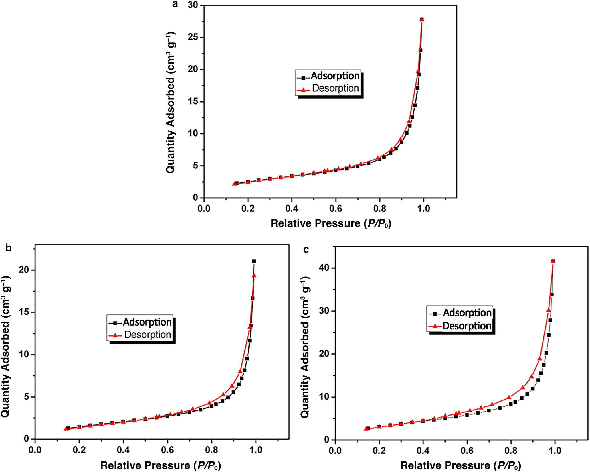
Fig. 12. Nitrogen adsorption isotherms of (a) S0, (b) S4 and (c) S5.
The loose powder state of S0, S4 and S5
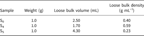
The loose bulk volumes of 1 g of S0 and S4 were 2.50 and 1.70 mL, corresponding to loose bulk densities of 0.40 and 0.59 g mL–1, respectively (Fig. 13 & Table 1). This suggests that the loose bulk volume and pores between the particles in S4 were smaller and that the aggregate of the sheet layers was more compact than in S0 (Fig. 11a). This is attributed to the fact that organic ammonium cations entered the interlayer of sericite and enlarged its interlayer spacing, causing aggregation of sericite particles. In addition, the loose bulk volume of 1 g of S5 was greater and the loose bulk density was smaller than those of S0 and S4, indicating that the structure of S5 was very loose and easy to disperse (Fig. 11b). This might be because chain hydrocarbons on the surface of sericite mica prevented sheet layers from accumulating with each other after modification of S4 by KH550. However, there is limited previous work on the loose state of sericite mica.
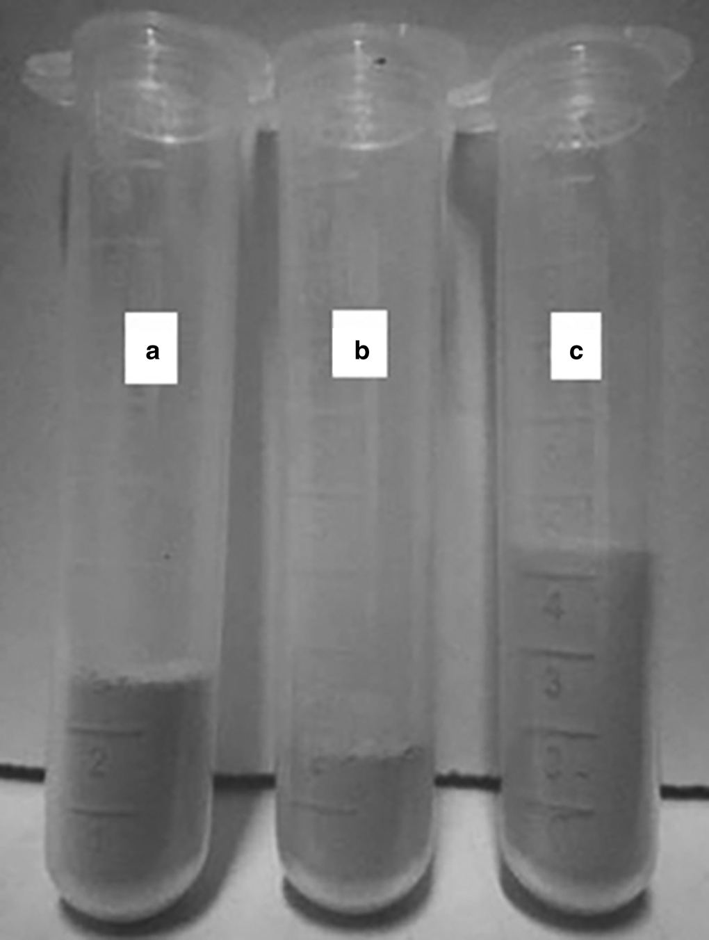
Fig. 13. Swelling volumes of 1 g of (a) S0, (b) S4 and (c) S5.
Table 1. The loose bulk volume and density data for S0, S4 and S5.
Conclusions
Sericite mica was modified by combining the intercalation of CTAB through ion exchange and surface modification with KH550. The effects of various activation temperatures on the surface modification of sericite were investigated. The number of hydroxyls of sericite decreased with increasing activation temperature, but the structure was almost unaffected when thermal activation was conducted at <600°C and 700°C. In contrast, the structure of sericite was partially destroyed at 800°C. After the activated sericite mica was modified by KH550, the decrease in the number of hydroxyls did not affect the grafting of KH550. S700 displayed a greater grafting rate of KH550 than S600 and S0. The optimal activation temperature of sericite was 700°C. KH550 was not only chemically grafted onto the surface of sericite particles, but also entered the sericite mica interlayer through electrostatic attraction after the end amino groups were protonated. The interlayer spacing of modified sericite mica increased to 3.22 nm, yielding a greater loose bulk volume. The preparation of modified sericite mica would be of great value for improving its dispersion in polymer matrices and its compatibility with polymers, as well as for developing clay–polymer nanocomposites for various applications.
Financial support
This work was supported financially by the Key Research and Development Project of Hunan Province ‘Research on Key Technologies of Advanced Functional Polyimide Materials’ under Grant Number 2018GK2063.


