


The collision of the Eurasian and the African plates renders the southern Iberian Peninsula a tectonically active area. Many active faults have been recognized, including the Alhama de Murcia, Baza, Carboneras and Palomares faults, some of which have recently been responsible for large-magnitude earthquakes, such as the 5.1 magnitude Lorca earthquake in May 2011. This earthquake caused significant damage in the Murcia region, a total of nine deaths and an estimated 400 injuries.
The internal structure of these major strike slip fault zones has been studied thoroughly in the past (Alhama de Murcia: Masana et al., Reference Masana, Martínez-Díaz, Hernández-Enrile and Santanach2004; Baza: Alfaro et al., Reference Alfaro, Delgado, de Galdeano C., Galindo-Zaldívar, García-Tortosa, López-Garrido, López-Casado, Marín, Gil and Borque2008; Carboneras: Faulkner et al., Reference Faulkner, Lewis and Rutter2003; Rutter et al., Reference Rutter, Faulkner and Burgess2012; Palomares: Booth-Rea et al., Reference Booth-Rea, Azañón, Azor and García-Dueñas2004; among others), but less attention has been given to mineralogical and microstructural characterization and to the physical processes related to the accommodation of the deformation in the mineral phases in fault rocks (e.g. for Carboneras and Palomares faults, see Jiménez-Millán et al., Reference Jiménez-Millán, Abad, Hernández-Puentes and Jiménez-Espinosa2015; Abad et al., Reference Abad, Jiménez-Millán, Schleicher and van der Pluijm2017).
The role of phyllosilicates within active fault systems and in relation to earthquake dynamics is a field of ongoing research. The brittle deformation of rocks in active fault systems increases the interaction between low-temperature fluids and rocks and frequently causes an enrichment of clay minerals (illite, chlorite, smectite and interstratifications of these clays) (Evans & Chester, Reference Evans and Chester1995; Solum et al., Reference Solum, van der Pluijm, Peacor and Warr2003; Torgersen & Viola, Reference Torgersen and Viola2014). Understanding the genetic relations affecting clays in low-temperature geological environments is complicated by the absence of chemical equilibrium, the small grain size (which makes textural studies difficult) and the identification of common intergrowths of phases. Some of the key factors controlling active deformation processes in large fault zones are: (1) the clay mineral assemblages; (2) the chemical composition and swelling behaviour of clay minerals; and (3) the influence of clay minerals on fluid circulation properties (e.g. Sibson, Reference Sibson1986; Vrolijk & van der Pluijm, Reference Vrolijk and van der Pluijm1999). In addition, the occurrence of clay-rich fault rocks has been suggested as contributing to the weakening of faults (Wang, Reference Wang1984; Imber, Reference Imber, Holdsworth, Butler and Strachan2001; Lockner et al., Reference Lockner, Morrow, Moore and Hickman2011) and is possibly a controlling factor in governing seismic stick-slip vs. creep mechanisms (Faulkner et al., Reference Faulkner, Lewis and Rutter2003; Schleicher et al., Reference Schleicher, van der Pluijm and Warr2010; Torgersen & Viola, Reference Torgersen and Viola2014) due to their low friction coefficients, continuous layers of water on their main cleavage planes and velocity-dependent behaviour (mechanical stability under friction) (Lockner et al., Reference Lockner, Morrow, Moore and Hickman2011; Schleicher et al., Reference Schleicher, Hofmann and van der Pluijm2013).
In this study, X-ray diffraction (XRD), scanning electron microscopy (SEM), transmission electron microscopy (TEM) and the electron microprobe have been used to characterize the fault-rock mineralogy of the most seismic segment of the Alhama de Murcia Fault (AMF), placing special emphasis on the clay mineralogy. This petrographic characterization of fault rocks aimed to determine the potential neoformation of clay minerals during faulting and to evaluate the possible influence of the mineralogy, especially the phyllosilicates, on the seismic activity and frictional properties of this fault (Niemeijer & Vissers, Reference Niemeijer and Vissers2014).
Geological setting and materials
The Betic Cordillera (southern Spain) is the westernmost European Alpine chain. This ENE–WSW-trending fold-and-thrust belt is composed of the External Zone and the Internal Zone, or Alboran domain (Fig. 1a). The External Zone is characterized by Mesozoic to Tertiary rocks corresponding to the Iberian Plate palaeomargin, situated on top of the Variscan basement. The Internal Zone consists of a thrust stack of metamorphic complexes affected by major tectonism and large displacements during the early Miocene (Sanz de Galdeano, Reference Sanz de Galdeano1990). Superimposed on these structures are Neogene to Quaternary sediments filling the intramontane basins, limited by E–W and NE–SW faults (Montenat & Ott D'Estevou, Reference Montenat, Ott D'Estevou, Friend and Dabrio1995). Moreover, Middle Miocene to Pleistocene calc-alkaline to K-rich volcanic rocks crop out in the Cabo de Gata area (Duggen et al., Reference Duggen, Hoernle and van der Bogaard2004).
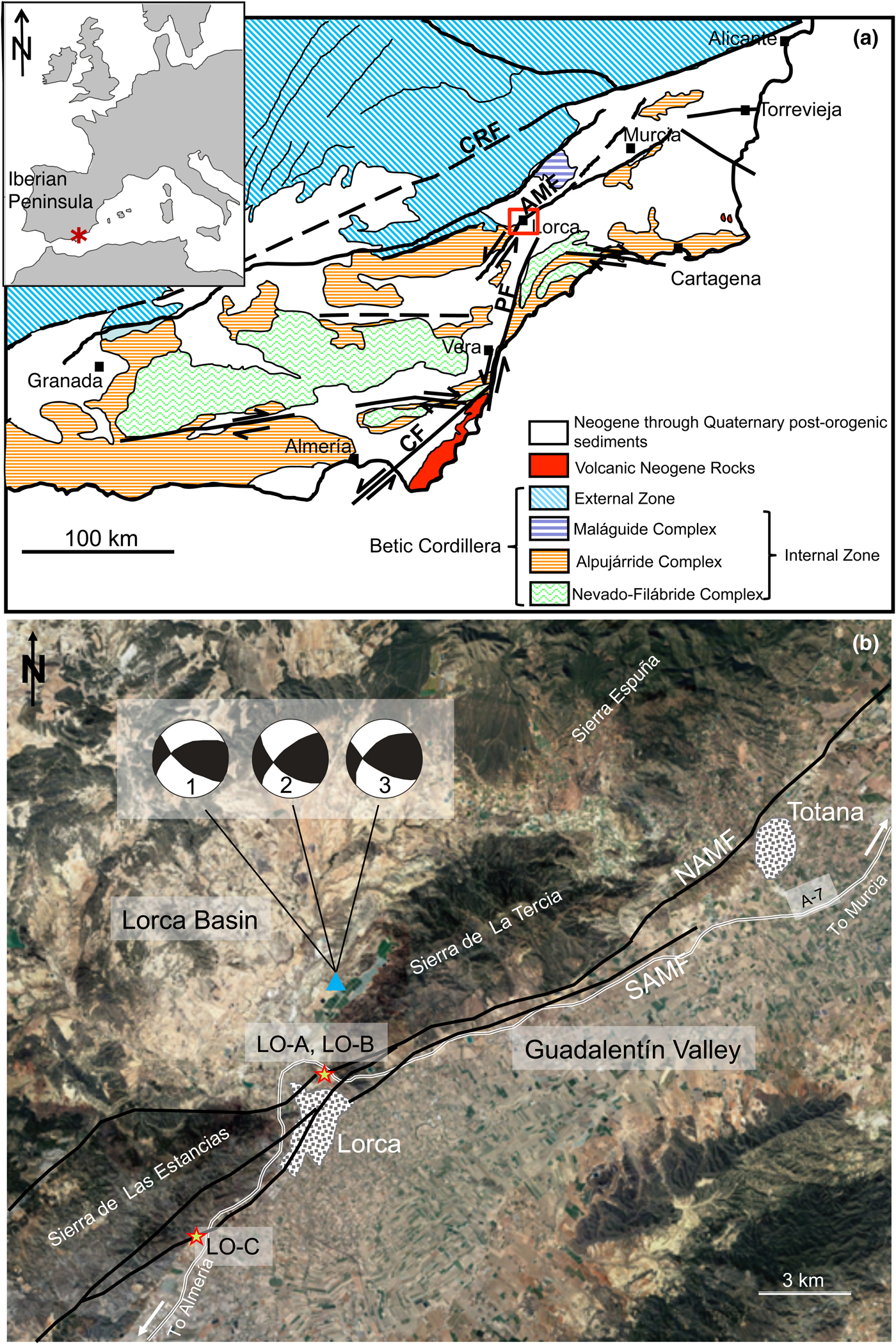
Fig. 1. (a) Geological map of the Trans-Alborán Shear Zone with the main Neogene faults (SE Spain) and the location of the study area. AMF = Alhama de Murcia Fault; CF = Carboneras Fault; CRF = Crevillente Fault; PF = Palomares Fault. Modified from Gracia et al. (Reference Gracia, Pallas and Soto2006). (b) Location map with the projection of the Alhama de Murcia Fault (NAMF and SAMF, Northern and Southern branches of the fault, respectively) including the sampling points (LO-A, LO-B and LO-C). The triangle is the mainshock of the Lorca 2011 seismic sequence taken from López-Comino et al. (Reference López-Comino, Mancilla, Morales and Stich2012). Focal solutions of the mainshock from several agencies are shown (1 = Instituto Andaluz de Geofísica; 2 = Instituto Geográfico Nacional; 3 = Harvard University).
The Neogene and Quaternary faulting activity in the southeastern Iberian Margin (Trans-Alboran Shear Zone) is dominated by a large NE–SW left-lateral strike-slip fault system, which is responsible for the intense deformation of the alpine crystalline protoliths. The biggest sinistral strike-slip faults are the Carboneras Fault (Bell et al., Reference Bell, Amelung and King1997), the Palomares Fault (Booth-Rea et al., Reference Booth-Rea, Azañón, Azor and García-Dueñas2004) and the AMF (Martínez-Díaz et al., Reference Martínez-Díaz, Béjar-Pizarro, Álvarez-Gómez, Mancilla, Stich, Herrera and Morales2012a, Reference Martínez-Díaz, Masana and Ortuño2012b) (Fig. 1). This system is by far the longest continuous fault system mapped in the Betic Cordillera and therefore would be expected to generate large-magnitude earthquakes (Gracia et al., Reference Gracia, Pallas and Soto2006). However, seismicity in the area is mainly characterized by low- to moderate-magnitude events. Nevertheless, occasional large, destructive earthquakes have occurred in the region, therefore comprising significant earthquake and tsunami hazards to the coasts of Spain and North Africa (IGN, 2001; Masana et al., Reference Masana, Martínez-Díaz, Hernández-Enrile and Santanach2004).
The AMF trends NE–SW with a 55°–65° NW dip and extends for 100 km from the Huercal-Overa depression to the outskirts of Murcia (Fig. 1). The history of the AMF reflects the tectonic inversion from an extensional to a strike-slip tectonic setting that occurred in the eastern Betics (Ferrater et al., Reference Ferrater, Booth-Rea, Pérez-Peña, Azañón, Giaconia and Masana2015). The tectonic inversion prompted large Pliocene to Quaternary strike-slip faults to reactivate previous Late Miocene normal faults associated with NW–SE and NE–SW extension (Meijninger & Vissers, Reference Meijninger and Vissers2006) within a diffuse plate boundary where African and Eurasian plates currently converge at a rate between 4 and 5 mm/year (Alfaro et al., Reference Alfaro, Delgado, García-Tortosa, Lenti, López, López-Casado and Martino2012). From the Late Miocene to the present, the faulted basement has been folded and uplifted (Alfaro et al., Reference Alfaro, Delgado, García-Tortosa, Lenti, López, López-Casado and Martino2012) and strike-slip tectonics dominate, especially along the NE–SW faults. According to Meijninger & Vissers (Reference Meijninger and Vissers2006), the AMF initiated its activity during the Late Miocene, thus producing an ‘intra-Tortonian unconformity’; the presence of tilted sediments underlying this unconformity cut by extensional normal faults suggests that the AMF should have started its activity after the Tortonian. The oldest alluvial fans related to the AMF were deposited during the Pleistocene, indicating that strike-slip activity and folding associated with the AMF was probably initiated during the Pliocene or Quaternary (Meijninger & Vissers, Reference Meijninger and Vissers2006).
According to Martínez-Díaz et al. (Reference Martínez-Díaz, Béjar-Pizarro, Álvarez-Gómez, Mancilla, Stich, Herrera and Morales2012a), the AMF is subdivided into four segments: (1) Goñar–Lorca (37 km), with moderate concentration of epicentres and the evident relief of the Las Estancias range; (2) Lorca–Totana (16 km), where the fault controlled the evolution of the Neogene Lorca basin, where Quaternary sediments are trapped by the recent activity of the fault and with the maximum concentration of seismicity; (3) Totana–Alhama de Murcia (17 km); and (4) Alhama de Murcia–Alcantarilla (23 km), which controlled the evolution of a depression to the NW, but shows little geomorphological fault expression.
Twenty-seven samples were collected from the Lorca–Totana segment (Fig. 1b, Table 1), which is a 16 km-long structure composed of two main NE–SW fault branches: (1) a northwestern steeply dipping reverse fault (70° NW) bounding the La Tercia range to the SE; and (2) a southeastern left-lateral and high-angle reverse fault dipping to the SE with oblique slip. The studied samples belong to the first fault branch, where the fault deforms the Alpujárride Complex, one of the thrust stacks of the metamorphic complexes within the Betic Internal Zone. The samples were taken directly from the fault plane of the AMF, including a trench uncovered after the 2011 earthquake (Fig. 2). During the collection, the outer 10–20 cm of material was removed to avoid any contamination of samples by surface weathering.

Fig. 2. View of the outcrops. (a) Detail of fault rocks. (b) Trench where samples LOA16–19 were collected.
Table 1. Sample list of the studied rocks with the geographic coordinates and bulk mineralogy determined by XRD and SEM.
Abbreviations of mineral names after Whitney and Evans (Reference Whitney and Evans2010).
In italics are samples studied by SEM; in bold are samples studied by HRTEM.
Methodology
X-ray diffraction data were obtained from random powders and oriented aggregates (whole-rock samples and <2 µm fractions) after washing with distilled water to remove salts. Oriented aggregates were prepared by sedimentation on glass slides and the <2 µm fraction was separated by centrifugation. Ethylene glycol (EG) solvation allowed the identification of expandable minerals (smectite, interstratified layers, etc.).
X-ray diffractograms were obtained with a PANalytical X'Pert Pro diffractometer (Cu-Kα radiation, 45 kV, 40 mA) equipped with an X'Celerator solid-state linear detector, using a step increment of 0.008°2θ and a counting time of 10 s/step (Department of Mineralogy and Petrology, University of Granada). Scans between 3° and 62°2θ were performed for the dry samples, while for the EG-solvated samples scans were performed between 2° and 30°2θ to identify expandable minerals. The basal spacing of micas (d 001) was determined precisely from the (00,10) reflection using the quartz of the sample as the internal standard.
Carbon-coated, polished, thin sections were examined by SEM using back-scattered electron (BSE) imaging in atomic number contrast mode and energy-dispersive X-ray (EDX) analysis to obtain textural and chemical data. These observations were carried out with a Merlin Carl Zeiss scanning electron microscope at the Centro de Instrumentación Científico-Técnica, CICT (University of Jaén) and a Leo 1430-VPSEM at the Centro de Instrumentación Científica, CIC (University of Granada). An accelerating voltage of 20 kV with a beam current of 1–2 nA and counting time of 50 s were used to analyse the silicates by SEM using the following standards: albite (Na), periclase (Mg), wollastonite (Si and Ca) and orthoclase (K) and synthetic Al2O3 (Al), Fe2O3 (Fe) and MnTiO3 (Ti and Mn). Analytical data were ZAF (atomic number, absorption and fluorescence) corrected. Electron probe microanalysis (EPMA) of micas corresponding to different textural zones was performed by wavelength-dispersive spectroscopy (WDX) on a Cameca SX100 at the CIC (University of Granada). The instrument was set at an accelerating voltage of 15 kV, with a beam current of 15 nA and an electron beam diameter of <5 µm. Data were reduced using the procedure of Pouchou & Pichoir (Reference Pouchou, Pichoir and Armstrong1985) and the standards used were albite, sanidine, periclase, diopside, quartz, vanadinite, rutile, fluorite and synthetic oxides (Al2O3, Fe2O3, NiO and MnTiO3).
3 mm copper rings with a 1 mm-diameter hole were glued with an epoxy resin to the areas selected for further study by high-resolution TEM (HRTEM). After drying for 24 h, the rings were removed by heating the thin section. The rings were cleaned and ion-thinned to a suitable thickness for TEM study in a Fischione-1010 ion mill (CICT, University of Jaén). The initial conditions for the ion thinning were 12°, 5 kV and 5 mA until the first hole opened; from there, they underwent an intermediate stage with 8°, 4 kV and 5 mA, followed by a final stage with 5°, 3 kV and 5 mA.
The HRTEM data were obtained using a Philips CM20 scanning transmission electron microscope (STEM), operated at 200 kV and with a point-to-point resolution of 0.27 nm in TEM mode and 5 nm in STEM mode at the CIC (University of Granada).
Results
The bulk-rock samples and oriented clay fractions contain abundant K- and Na-dioctahedral micas and minor quartz. Carbonates (calcite and/or dolomite), gypsum, chlorite and hematite are present only in some samples (Fig. 3). There were no significant changes after EG solvation, indicating the absence of expandable phases such as smectite, except for minimal amounts in two samples. Kaolinite is present in all samples (Table 1).

Fig. 3. Representative X-ray diffractograms corresponding to samples from Alhama de Murcia Fault rocks. Inset: Enlarged (00,10) mica peak region, showing the presence of only two peaks corresponding to muscovite (phengite) and paragonite. Cal = calcite; Dol = dolomite; Chl = chlorite; Hem = hematite; Ilt = illite; Kln = kaolinite; Ms = muscovite; Pg = paragonite; Qz = quartz.
Polished thin sections from the fault rocks show that they are composed of very fine-grained and well-developed gouge material (Fig. 4).

Fig. 4. BSE images showing the textural aspect of the fault rocks. (a) Fine-grained material corresponding to the gouge with poorly sorted quartz grains with irregular shapes and Fe-oxides. (b) Phyllosilicates stacks with curved shapes and signs of grain-size reduction (arrow).
Specifically, rocks from the fault core are made of:
a) Foliated bands (>100 µm thick) that are rich in well-crystallized muscovite, paragonite and quartz, including dolomite and hematite crystals frequently >20 µm in size (Fig. 5a). In some cases, dolomite grains exhibit intact cores and rims with localized disaggregation, holes and Fe-oxide crystallization (Fig. 5b).
b) Thin, ultrafine-grained bands (<100 µm thick) characterized by the presence of numerous holes and vesicles (Fig. 5c). These domains are made of patches of small crystals (<15 µm) with mica bulk composition. These patches host dispersed crystals of Fe-oxide and a network of dolomite skeletal crystals (Fig. 5d,e).
c) Patches of kaolinite made of randomly oriented crystals ranging in size from 30 µm to <2 µm and usually filling gaps in the rock structure (Fig. 5b). Kaolinite are also observed in foliated bands associated with K- and Na-micas, with the same orientation and sometimes intergrown in stacks (Fig. 5e,f).
Fig. 5. BSE images of the fault rocks. (a) An example of a foliated band composed of micas, quartz and Fe-oxides. (b) Dolomite grain showing rims with localized disaggregation and Fe-oxide crystallization, partially surrounded by a patch of kaolinite. (c) Poorly crystalline material characterized by the presence of numerous holes alternating with thin and very-fine-grained phyllosilicate bands. (d) Detail of the network of dolomite skeletal crystals between two foliated bands. (e) Another example of the network between phyllosilicate bands, one of them with a stack of kaolinite with some K-mica packets intergrown (white arrows). (f) Detail of the patch of kaolinite from (b), in which mica packets intergrown with kaolinite (white arrows) are distinguished. Dol = dolomite; Hem = hematite; Kln = kaolinite; Ms = K-rich dioctahedral mica; Pg = Na-rich dioctahedral mica; Qz = quartz.
At TEM scale, the mineralogical characterization of the samples confirms the data obtained by XRD and SEM. Some areas contain large and well-crystallized packets of dioctahedral micas (several hundreds of nanometres in size) with a 2M polytype (Fig. 6a), probably related to the thick foliated bands described by SEM. There are also smaller mica grains (<100 nm) with strain contrast orthogonal or oblique to the lattice fringes, probably generated by tectonic stress (Fig. 6b,c). Kaolinite packets forming aggregates of parallel and subparallel grains were identified inside voids (Fig. 7a). In addition, electron diffraction images showed that, in some areas, paragonite, muscovite and kaolinite form parallel or low-angle intergrowths at the nanoscale (Fig. 7b). These intergrowths are not very obvious in the lattice fringe images due to the fast beam damage of the kaolinite packets. Fe-oxide aggregates, formed by randomly oriented and prismatic grains, were also identified at the nanometre scale (Fig. 8).
Fig. 6. (a) TEM lattice fringe image with large dioctahedral mica crystals showing a 2 nm periodicity; the electron diffraction pattern shows the presence of basal spacings corresponding to paragonite (0.96 nm) and muscovite (1 nm). (b, c) TEM lattice fringe images corresponding to thin dioctahedral mica packets with a very damaged appearance (see arrows).

Fig. 7. (a) Low-magnification image of a kaolinite aggregate surrounded by quartz grains. (b) Selected area electron diffraction showing the parallel and subparallel relations between dioctahedral micas and kaolinite. Kln = kaolinite; Qz = quartz.

Fig. 8. Low-magnification image of an Fe-oxide aggregate at nanoscale. Cb = carbonates (calcite and dolomite); Hem = hematite; Ms = K-rich dioctahedral mica; Qz = quartz.
Chemical analyses obtained by SEM-EDX and EPMA give similar results (Fig. 9, Tables 2, 3). Both K- and Na-dioctahedral micas are present. K-dioctahedral micas corresponding to the foliated bands with well-crystallized grains are characterized by compositions typical of muscovites or phengites rather than illites. The phengitic component is the main component responsible for the negative correlation between Al and Fe + Mg octahedral atoms (Fig. 9a). The sum of interlayer cations is, in most cases, higher than 0.85 atoms per formula unit (apfu) (Fig. 9b), and some of the analysed K-micas have significant Na content (up to 0.30 apfu) (Fig. 9c,d). The mica crystals analysed in the thin, ultrafine-grained bands also have a sum of interlayer cations that is very similar to the well-crystallized grains of the foliated bands (Fig. 9b). Nevertheless, the Na/K ratio shows a rather wider range than that of the micas from the foliated bands (Fig. 9c,d), covering all of the field of intermediate compositions between K and Na. They show in general a larger variation in chemical composition, whereas the well-crystallized grains from the foliated bands show much less difference. Muscovitic, phengitic, intermediate Na/K and paragonitic compositions have been identified in the ultrafine-grained bands with predominance of the intermediate Na/K-micas (Fig. 9, Tables 2, 3). In addition, in Fig. 9, chemical data corresponding to the 2M K-dioctahedral micas from the Alpujárride protolith in the area of Sierra Espuña (Abad et al., Reference Abad, Nieto, Peacor and Velilla2003) have been included for comparison.

Fig. 9. Relationships among the chemical components of the dioctahedral micas studied by SEM/EDX and EPMA/WDX. (a) Al vs. Fe + Mg; (b) Si vs. K + Na + Ca; (c) K vs. Na; (d) Na/Na + K vs. Si/Al. Black circles and solid lines indicate the theoretical muscovite position and corresponding exchange vectors, respectively.
Table 2. Electron microprobe analyses (wt.%) for dioctahedral micas.

Table 3. Structural formulae for dioctahedral micas normalized to O10(OH)2 on the basis of SEM/EDX and EPMA/WDX data.

inter. = interlaminar cations; oct. = octahedral.
The trioctahedral chlorites, which have an Fe/(Fe + Mg) ratio of ~0.60, correspond mainly to the chamosite (Fe-rich) variety (Table 4). The octahedral sums are near 6, which precludes the application of chlorite geothermometry, as such values render the margin of error of the method unacceptable; however, together with the low Si content, they are characteristic of high-temperature chlorites (Bourdelle & Cathelineau, Reference Bourdelle and Cathelineau2015; Vidal et al., Reference Vidal, Lanari, Munoz, Bourdelle and de Andrade2016). Kaolinite analyses fit the theoretical formula of a pure, Al-rich composition (Table 4).
Table 4. Structural formulae for chlorites and kaolinites normalized to O10(OH)8 on the basis of SEM/EDX data.

oct. = octahedral.
Discussion
Neoformation of clay minerals in the AMF
The compositional differences between the well-crystallized packets of dioctahedral micas (mostly muscovites, with some phengitic component) and the mica crystals analysed in the thin, ultrafine-grained bands with predominance of intermediate compositions between muscovite and paragonite (Figs 9, 10) suggest they have different origins. The compositions determined by EPMA for the micas of the thin, ultrafine-grained bands are well within the compositional gap between muscovite and paragonite (Guidotti et al., Reference Guidotti, Sassi, Blencoe and Selverstone1994; Coggon & Holland, Reference Coggon and Holland2002; Parra et al., Reference Parra, Vidal and Agard2002). They might correspond to the so-called interstratified paragonite/muscovite (Frey, Reference Frey1969, Reference Frey1978) or metastable intermediate Na/K-mica (Jiang & Peacor, Reference Jiang and Peacor1993), later interpreted by Livi et al. (Reference Livi, Christidis, Árkai and Veblen2008) as white mica nanodomains. Nevertheless, such a mineral entity is characterized in all of the described cases (cited references in the two previous sentences) by an intermediate peak at 0.98 nm, which in the AMF samples is completely absent. The areas of the diagrams corresponding to the (00,10) peaks of micas show two well-differentiated peaks, corresponding to muscovite (or phengite) and paragonite, respectively (Fig. 3, inset). Therefore, the small mica crystals shown in the thin, ultrafine-grained bands (Fig. 10a) are interpreted only submicroscopically as paragonite and phengite intergrowths under the resolution of compositional maps (Fig. 10b,c,d) and microanalyses of EPMA (Fig. 9), as is frequently described in the literature (e.g. Shau et al., Reference Shau, Feather, Essene and Peacor1991; Livi et al., Reference Livi, Christidis, Árkai and Veblen2008 and references therein). In conclusion, most compositions of the thin, ultrafine-grained bands determined by EPMA and SEM do not correspond to individual mica grains, but rather represent mixed compositions of a fine intergrowth between Na- and K-micas under the resolution of EPMA and SEM analyses (~2 µm).
Fig. 10. BSE image (a) and K, Al and Na X-ray maps (b, c and d, respectively) of one of the selected zones analysed by EPMA and processed with ImageJ, where well-crystallized muscovites (right) and a fine-grained phyllosilicate band mainly composed of Na/K-micas (left) are observed.
To compare the real Na/K content of the micas in the thin, ultrafine-grained bands with that of the foliated bands, an indirect approach was used that was free of the effects of their mutual contamination. As K has a significantly larger atomic radius than Na, the d 001 of micas is deeply influenced by the Na/K ratio (Guidotti et al., Reference Guidotti, Mazzoli, Sassi and Blencoe1992). The lattice parameters depend on the average compositions of the minerals at the lattice level; hence, they are free of the effects of mutual contamination by the two micas. The measurement of the d 001 parameter of the K-dioctahedral micas in oriented aggregates of the <2 µm and whole fractions allows us to consider whether the former include predominantly the small micas of the thin, ultrafine-grained bands, while the latter include the two kinds of micas (foliated and ultrafine-grained bands). A clear difference between the two populations is observed (Fig. 11), with the d 001 of micas of the <2 µm fraction being greater, which indicates a higher K and lower Na content (Guidotti et al., Reference Guidotti, Mazzoli, Sassi and Blencoe1992) of the small micas in the thin, ultrafine-grained bands. As the two end members of the muscovite-paragonite solvus are present (Fig. 3), more extreme compositions, which have a higher K content in muscovite limb of the solvus, represent a lower temperature of formation (Guidotti et al., Reference Guidotti, Sassi, Blencoe and Selverstone1994; Coggon & Holland, Reference Coggon and Holland2002; Parra et al., Reference Parra, Vidal and Agard2002). This lower temperature is probably responsible for the very small grain size of the components of the intergrowth between K- and Na-micas. It is concluded that the micas of the thin, ultrafine-grained bands have a different composition from those of the foliated bands, and this composition corresponds to a lower temperature of formation. Therefore, the micas in the thin, ultrafine-grained bands do not simply result from the breaking and reorientation of the larger metamorphic mica crystals of the original rocks, but rather they have grown during a genetic episode in the fault. The reasonably wide range of values of phengitic content of micas inherited from the protolith at the sample level is a common characteristic of the Alpujárride rocks and is a consequence of the isothermal decompression path followed by the Alpujárride Complex from at least 10 kbar (Azañón & Crespo-Blanc, Reference Azañón and Crespo-Blanc2000).

Fig. 11. Comparison between the mica d 001 spacings of the <2 µm and whole fractions of the studied samples, calculated from the position of the (00,10) K-dioctahedral mica peak. TOA = total oriented aggregates.
Chlorite is the other common phyllosilicate in the Alpujárride rocks. In the fault samples, all of the analysed chlorites show low Si content and octahedral sums near 6 (Table 4), indicating high amesite and low sudoite components, respectively, which, in turn, indicate a high temperature of formation of the chlorites, but preclude an exact determination of the temperature (Bourdelle & Cathelineau, Reference Bourdelle and Cathelineau2015; Vidal et al., Reference Vidal, Lanari, Munoz, Bourdelle and de Andrade2016). Therefore, similarly to the micas of the foliated bands, chlorites in the fault rocks have chemical characteristics that are similar to their counterparts of the protolith (Abad et al., Reference Abad, Nieto, Peacor and Velilla2003), suggesting a metamorphic origin.
In fact, the protolith of the studied rocks is a grey phyllite that is widely distributed in all of the Alpujarride Complex, which may be described from the nearest outcrops in the southern part of Sierra Espuña (Fig. 1b). These rocks are composed of K- and Na-dioctahedral micas, chlorite, quartz, hematite, carbonates (calcite and dolomite) and retrograde smectite (Nieto et al., Reference Nieto, Velilla, Peacor and Ortega-Huertas1994). The large amounts of K- and Na-micas in the fault rocks are consistent with the mineralogy of the protolith, which was characterized in detail by Abad et al. (Reference Abad, Nieto, Peacor and Velilla2003). Nevertheless, the textural differences between the Alpujárride protolith and the fault rocks are remarkable: a well-developed foliation in the phyllites, affecting even quartz, oxide and carbonate grains (e.g. see fig. 3 in Abad et al., Reference Abad, Nieto, Peacor and Velilla2003), compared with the very-fine-grained breccias in the fault rocks (Figs 4, 5). In addition, to our knowledge, kaolinite has not been described in the protolith, which is at odds with its ubiquitous presence in all of the samples collected in or near the fault plane (Table 1).
The presence of authigenic kaolinite should be related to the fluid–rock interaction along fault planes and fractures. In some cases, kaolinite is finely intergrown with small mica crystals (Figs 5e,f, 7b). Figure 5e shows how the newly formed kaolinite opens the layers of presumably inherited detrital mica crystals. This has been interpreted traditionally as an epitaxial growth from fluids, in which the mica layers act as templates facilitating kaolinite growth (cf. Arostegui et al., Reference Arostegui, Irabien, Nieto, Sangüesa and Zuluaga2001 and references therein). In other cases, kaolinite forms patches of randomly oriented crystals filling gaps in the rock structure. We have not found any proof of transformation of previous mica by kaolinite by means of a topotaxial mechanism. Overall, the textural relationships between mica and kaolinite indicate that the latter grew after the former from a fluid. Given the stability field of kaolinite, its growth was a low-temperature process (<200°C); however, it is difficult to establish from the available data whether such a process is related to the final step of the hydrothermal activity in the fault or whether it is the result of meteoric infiltration.
The role of clay minerals in the mechanical behaviour of the fault
Niemeijer & Vissers (Reference Niemeijer and Vissers2014) studied the frictional properties of the AMF rocks that ruptured during the 2011 earthquake, which included fault gouges and elongated lenses of phyllites from the protolith embedded in a cataclastic matrix. They identified greater frictional strength (μ) in the protolith-derived lenses (μ from 0.50 to 0.70 at room temperature and from 0.70 to 0.80 at elevated temperatures) than the gouge-derived samples (μ from 0.35 to 0.60 at room temperature and from 0.40 to 0.50 at elevated temperatures). The lower friction coefficients are consistent with the larger amounts of weak phyllosilicates identified in the gouges, which, in addition to contributing to fault weakness, also impact the mechanical stability of the fault under shear. The mechanical stability is also known as the velocity or rate dependence, where the friction rate parameter (a-b) describes the stability of the sliding surface. A positive value of a-b indicates velocity strengthening leading to fault creep, while negative values of a-b correspond to velocity weakening that may result in earthquake nucleation (Scholz, Reference Scholz1998). Gouges from the AMF show velocity-strengthening properties that migrate to a velocity-neutral value under simulated shallower conditions (Niemeijer & Vissers, Reference Niemeijer and Vissers2014). However, the protolith-derived lenses show velocity-weakening properties, which suggests that earthquakes in the AFM are nucleated in these protolith-derived lenses. The occurrence of phyllosilicates or other weak minerals in a fault zone may promote distributed deformation and provide an explanation for fault weakness (Faulkner et al., Reference Faulkner, Lewis and Rutter2003, Reference Faulkner, Jackson, Lunn, Schlische, Shipton, Wibberley and Withjack2010; Collettini et al., Reference Collettini, Niemejer, Viti and Marone2009).
Fragile behaviour of stronger minerals with high friction values and velocity-weakening behaviour such as quartz (0.6 < μ < 0.7; Byerlee, Reference Byerlee1978; Dieterich & Kilgore, Reference Dieterich and Kilgore1994) may lead to cataclastic textures that increase rock permeability and create permeable paths. Fluid–rock interaction within the paths produces leaching of the host rocks and favours the crystallization of new minerals: submicroscopically, paragonite and phengite intergrowths located in the thin, ultrafine-grained bands and the rounded to lens-shaped micropods of kaolinite. In addition to the mineral changes, the interaction of low-temperature fluids and the fault rocks modifies the microstructural features of the gouges and might, as a consequence, alter the stability of the fault plane.
In particular, the authigenesis of expandable clay minerals in fault gouges may contribute to friction coefficients as low as 0.05 under wet conditions, as well as to velocity-strengthening behaviours (Lockner et al., Reference Lockner, Morrow, Moore and Hickman2011). For this reason, the expandable minerals have often been related to fault creep and mechanical stability, as in the case of the central segment of the San Andreas Fault (Lockner et al., Reference Lockner, Morrow, Moore and Hickman2011). Nevertheless, the AFM shows no evidence of authigenesis of expandable minerals in its fault gouges. On the contrary, all authigenic minerals are non-expandable. The frictional strength of kaolinite under wet conditions is high when compared with that of the expandable clay minerals: μ = 0.51 (Moore & Lockner, Reference Moore and Lockner2004), μ = 0.53 (Morrow et al., Reference Morrow, Moore and Lockner2000), μ = 0.29 (Behnsen & Faulkner, Reference Behnsen and Faulkner2012) and μ = 0.23 (Brantut et al., Reference Brantut, Schubnel, Rouzaud, Brunet and Shimamoto2008).
As suggested by frictional data (Niemeijer & Vissers, Reference Niemeijer and Vissers2014), earthquake nucleation in the AMF is concentrated in lenses of phyllitic basement rocks; immediately afterwards, rupture propagation takes place through the fault rocks. The absence of smectite within the fault gouges (only small amounts of smectite were identified in two of the studied samples) and the presence of kaolinite, quartz and micas may explain the observed velocity-neutral behaviour of this gouge and earthquake propagation towards the surface (Niemeijer & Vissers, Reference Niemeijer and Vissers2014) instead of the velocity-strengthening behaviour characteristic of weak phyllosilicates that is expected to represent a barrier to rupture propagation.
Author ORCIDs
Isabel Abad, 0000-0002-6354-0173
Acknowledgements
The authors thank J.A. López Martín for his time and advice during the sampling and Dr M.M. Abad-Ortega and A. Martinez-Morales for their support in electron microscopy data acquisition. The critical reviews and very helpful comments and suggestions of S.H. Haines and E. Torgersen have notably improved the quality of the paper. This work has been financed by Investigation Projects CGL2011-30153-C02-01 and CGL2011-30153-C02-02 from MINECO, Research Project UJA2014/06/17 from the Universidad-Caja Rural de Jaén, Research Groups RNM-179 and RNM-325 of the Junta de Andalucía and the FPI scholarship BES-2012-052 562 from the Spanish Government (MINECO).


