1. INTRODUCTION
As product development becomes more knowledge-intensive and collaborative, manufacturing companies are increasingly focusing on collaborative product design both to reduce total product development time and to increase efficiency of the product development process using emerging computer network technologies (Pegasus, 2003; Engineous, 2005). Heterogeneous tools and multiple designers are frequently involved in this network-based collaborative product design. To persistently capture designers' intentions and the semantics of the designers' terms, a standardized data format is a prerequisite. One designer's terms and definitions for aspects of a product's design could potentially be different from another's design, and therefore an obstacle to sharing design information with multiple designers. Furthermore, appropriate design knowledge should be provided during all design processes to make proper design decisions.
Within the physical structure of engineered products, joints are inevitable because of the limitations of component geometries and the required engineering properties. This implies that a framework is needed to capture and propagate assembly design and joint information in a robust assembly model throughout the entire product development processes, by an understanding of assembly geometry and its physical effects. However, the physical effects of joining processes are still a major problem related to quality and productivity (Beeson, Reference Beeson1999; Graf & Staufer, Reference Graf and Staufer2003) in manufacturing industries. Furthermore, current solid modelers and simulation software cannot provide either complete product definitions or the semantic content, because traditionally, the geometric model was in the center of product models. Even if geometry is of great importance during assembly design, the morphological characteristics are consequences of the principal physical processes and of the design intentions (Horváth et al., Reference Horváth, Pulles, Bremer and Vergeest1998; Kurland, Reference Kurland2003). Therefore, this assembly design and its associated morphological characteristics should be represented in a standard way and be transparently shared throughout the entire product development, while maintaining the association of assembly joint design and morphological characteristics that includes geometry and topology.
The role of the Semantic Web is to operate as one large virtual model base, because it is not a web of documents, but rather a web of relations among resources. It denotes that product models (including data, information, and objects), can be connected to the Internet, and that design collaborators can have ubiquitous access to a product model through a client interface, while understanding the semantics and context of information. In this manner, existing product models and associated knowledge can be reused. Reusing existing models of components and subassemblies is important for reducing model development time, while allowing cross-fertilization of knowledge across multiple product development projects. Even though many researchers have presented various different ontologies, from a cooperate level ontology (Gruber, Reference Gruber1993; Fox & Gruninger, Reference Fox and Grüninger1998; Mizoguchi, Reference Mizoguchi2003) to an engineering ontology (Lin et al., Reference Lin, Fox and Bilgic1996; Horváth et al., Reference Horváth, Pulles, Bremer and Vergeest1998; Kim, et al., Reference Kim, Manley and Yang2006), these all have limitations on representing mechanical assemblies and their complex morphological characteristics. Neither has it been reported how the morphological characteristics of assembly design should be represented in ontology or be shared in the network-based assembly design in an integrated manner.
Therefore, in our research, we present an ontology-based modeling framework that integrates assembly design and its associated morphological characteristics, including geometry and topology, for a network-based collaborative design environment. In this paper, we first define assembly design ontology and assembly hierarchical relationships using Semantic Web Rule Language (SWRL) rules and Web Ontology Language (OWL) triples. Second, the assembly topology is represented as a mereotopology, which is a region-based theory for the parts and associated concepts (Randell et al., Reference Randell, Cui, Cohn, Nebel, Swartout and Rich1992; Eschenbach, Reference Eschenbach1994). This formal ontology can be used to differentiate often ambiguous assembly and joining relations. Third, based on the assembly design ontology, the mereotopological definitions of assembly joints are implemented using SWRL rules and OWL triples. This process provides universality to the mereotopological definitions. Two geometrically and topologically similar joint pairs are presented to describe how the assembly joints can be defined in mereotopology and be transformed into SWRL rules. Fourth, we use Web3D to support network-enabled sharing of assembly geometry. Finally, the proposed framework is demonstrated using a real fixture assembly to show the usability of the proposed framework.
2. LITERATURE REVIEW
2.1. Network-enabled collaborative product design
Collaborative product design is increasingly seen as a viable alternative to the traditional product design process, in which a product design is developed through an iterative process among designers, analysis engineers, manufacturers, marketers, and customers (Pegasus, 2003; Engineous, 2005; PTC Global Service, 2007; Cocreate, 2008; Teamcenter, 2008). This trend is linked to the tremendous growth in the development of the Internet and associated technologies such as the Java programming language, as well as to the rapid advancements made in computing technology that have led to the proliferation of powerful, yet affordable computers. Several academic research groups have studied the possibility of a distributed environment for product designers and manufacturers. The examples of existing distributed design and manufacturing prototype systems are Next-Cut (Brown et al., Reference Brown, Cutkosky, Tenebaum, Sriram, Logcher and Fukuda1989), CyberCut (Smith & Wright, Reference Smith and Wright1996; Chui & Wright, Reference Chui and Wright1999), FixtureNet (Wagner et al., Reference Wagner, Castanotto and Goldberg1997), COCADCAM (Kao & Lin, Reference Kao and Lin1996, Reference Kao and Lin1998), interactive CAM designer of Larson and Cheng (Reference Larson and Cheng2000), WPDSS (Qiang et al., Reference Qiang, Zhang and Nee2001), and Pegasus e-Designer system (Kim & Nnaji, Reference Kim and Nnaji2003; Nnaji et al., Reference Nnaji, Wang and Kim2004).
The design of a mechanical product requires concurrent availability of dozens of technical supports from various engineering and nonengineering fields. Although we have seen several computational tools in those different areas, problems remain that inhibit the tools from working together automatically with little human intervention. These problems stem mostly from a lack of common protocols for them to communicate. To tackle these issues, both commercial and research groups investigate common formalisms and protocols necessary for collaborative engineering (Cutkosky et al., Reference Cutkosky, Tenenbaum and Glicksman1996; Krishnamurthy & Law, Reference Krishnamurthy and Law1997; Kim et al., Reference Kim, Kim, Kim, Kang and O'Grady1998; Deneux, Reference Deneux1999; Mueller, Reference Mueller1999; Rojas & Songer, Reference Rojas and Songer1999; Whitney et al., Reference Whitney, Mantripragada, Adams and Rhee1999; Florida-James et al., Reference Florida-James, Rossiter and Chao2000; van Holland & Bronsvoort, Reference van Holland and Bronsvoort2000; Shyamsundar & Gadh, Reference Shyamsundar and Gadh2002; PTC Global Service, 2007). However, their protocols and formalisms cannot be applied to assembly modeling that requires various joining processes. Kim et al. (Reference Kim, Wang, Muogboh and Nnaji2004) develop an assembly design formalism, which generates an XML-based meta-model called an assembly relation model (ARM) to explicitly represent the relations. Kim et al. (Reference Kim, Manley and Yang2006) also show the feasibility of an ontological representation of assembly relations and associated constraints. This paper further enhances the scope of the explicit representation and investigates how the morphological information of assembly joints can be represented in ontology and can be integrated for network-based design collaboration.
2.2. Ontology
Ontologies are explicit, formal specifications of terms in the domain and of the relations among them (Gruber, Reference Gruber1993); in other words, a formal, explicit specification of a shared conceptualization. Formal refers to the fact that the ontology should be machine-readable (Fensel, Reference Fensel2001). Mizoguchi (Reference Mizoguchi2003, Reference Mizoguchi2004a, Reference Mizoguchi2004b) presents the roles of an ontology as a common vocabulary, a data structure, an explication of what is left implicit; as semantic interoperability, as an explication of design rationale, as the systemization of knowledge, as a meta-model function, and as a theory of content. Ontologies have been developed for a variety of domains. The broadest of these are upper level ontologies that describe common sense-level knowledge in a machine-interpretable manner. Cycorp's CYC is a commercial ontology containing over 200,000 terms and assertions (Cycorp, 2008); however, it has not had a strong impact in the mechanical design domain, because CYC is still a high-level ontology. Nonetheless, in 1999, the National Institute of Standards and Technology chose CYC as an ontology for further investigation in the manufacturing domain (Schlenoff et al., Reference Schlenoff, Ivester, Libes, Denno and Szykman1999). The results from this investigation led to the development of Process Specification Language, a language that is generic enough to represent discrete manufacturing and construction process data (Gruninger et al., Reference Gruninger, Sriram, Cheng and Law2003). The other remarkable effort in ontology is the industry foundation class (IFC) model, which has been accepted by an open international standard for building information exchange (Katranuschkow et al., Reference Katranuschkow, Gehre, Scherer, Turk and Scherer2002; Bell & Bjørkhanug, Reference Bell, Bjørkhanug, Martinez and Scherer2006).
Narrower in scope than upper level ontologies, enterprise-level ontologies attempt to formalize the practices and processes that occur within an organization. The level of the concepts is enterprise specific, and the concepts are meant to promote knowledge reuse with regard to business decisions and transactions. An example of this is enterprise ontology (Uschold et al., Reference Uschold, King, Moralee and Zorgios1998), an ontology that defines the overall activities of an organization. Although it takes into account the business aspects of an organization, enterprise ontology does not define engineering activities in adequate detail. Similar to the overall goal of enterprise ontology, Toronto virtual enterprise (TOVE; Fox, Reference Fox1992; Fox & Gruninger, Reference Fox and Grüninger1998) is an ontology for enterprise knowledge. TOVE's results, particularly in the domain of products and requirements, are closer to the knowledge-intensive tasks of engineering design than enterprise ontology, yet they still do not adequately capture all the detailed forms of mechanical design knowledge.
Some ontological research has been applied at both the design and manufacturing levels. Kals et al. (Reference Kals, Mentink, Wijinker and Lutters2004) suggested information structure and a manufacturing ontology to integrate information and process associated to global manufacturing. Although they presented a comprehensive ontological framework for global manufacturing, detailed assembly and joint design issues were not reached. Kitamura et al. (Kitamura et al., Reference Kitamura, Kashiwase, Masayoshi and Mizoguchi2004; Kitamura & Mizoguchi, Reference Kitamura and Mizoguchi2004) successfully developed an ontology to represent functional design and deployed this ontology into industry. Although the Kitamura et al. work captures flow (e.g., the flow of fluids or the flow of parts in manufacturing), it has limitations on capturing complex mechanical phenomena. Horváth et al. (Reference Horváth, Pulles, Bremer and Vergeest1998) attempt to create an ontology for design features using ontology theory. They classify design concepts in terms of entities, phenomena, and situations. Liang and Paredis (Reference Liang and Paredis2004) develop a port ontology to capture form, function, and behavior aspects in conceptual design. Even though their ontology is a promising way to represent form, function, and behavior aspects of design knowledge, it is still unclear how specific joining knowledge can be integrated with assembly design knowledge.
2.3. Mereotopological ontology
Mereology literally means “science or theory of parts.” It is also the name of the formal theory of parts and associated concepts developed by Leśniewski (Reference Leśniewski1982). To distinguish his theory from other mereological theories, the theory of Leśniewski is referred to as “Mereology,” written with a capital M. Just as mereology is a theory for the part–whole relation in general, there is also a theory of the “is-connected-to” relation in general, which is called topology. A formal ontology can use topological means to derive ontological laws pertaining to the boundaries and interiors of wholes, to relations of contact and connectedness, and to the concepts of surface, point, neighborhood, and so forth (Randell et al., Reference Randell, Cui, Cohn, Nebel, Swartout and Rich1992). In using mereotopology as a formal ontology, a mereology formulates the standard treatments of topology in set-theoretic terms.
Perhaps most importantly for product modeling and computer-aided tools, region-based theories of mereotopology (Randell et al., Reference Randell, Cui, Cohn, Nebel, Swartout and Rich1992; Eschenbach, Reference Eschenbach1994) suggest that it can be used to represent entities that exist in other spaces besides the usual physical one. A region is a portion of a space, typically the portion occupied by some entity, whether material (e.g., a physical part) or otherwise (e.g., a hole). The overarching goal of any mereotopology theory is to describe the nature of regions and the entities that occupy them, and the interrelations between regions. Regions themselves, however, need not be primitive entities within the theories. There are many mereotopology theories that do not take regions as primitive entities (Casati & Varzi, Reference Casati, Varzi and Stock1997; Smith, Reference Smith and Hahn1997); rather, they build them up from more primitive entities. Salustri (Reference Salustri2002), and Eschenbach and Heydrich (Reference Eschenbach and Heydrich1995) suggest that regions in a mereotopology for design can be physical entities and nonphysical entities, such as boundaries, surfaces, points, and so forth, because they are generally accepted conceptual entities in engineering design.
To represent assembly joints, connectivity of individuals to which the part–whole relation applied is obviously important. There are two approaches to develop such a theory. One is to extend an existing theory of mereology with the topological is-connected-to relation. The other is to integrate mereological and topological concepts and relations into one mereotopological theory. Although the first approach is arguably more intuitive, the second usually leads to more compact theories because the axioms can be combined. Smith (Reference Smith1996) follows the second approach. Using Smith's (Reference Smith1996) mereotopology, regions in physical domains (e.g., parts and products), as well as nonphysical domains (e.g., form features) that are associated to assembly design formalisms, can be represented. In this paper, we use Smith's mereotopology to formally define the topology of assembly joints among morphological characteristics of assembly. The mereotopological modeling method is explained further in Section 4.2.
3. ONTOLOGY CONSTRUCTION FOR ASSEMBLY DESIGN
To ontologically model assembly joint design, we use OWL and SWRL. OWL is designed for use by applications that need to process the content of information, versus simply presenting information. By providing additional vocabulary along with a formal semantics, OWL facilitates greater machine interpretability of Web content than that supported by XML, Resource Definition Framework (RDF), or RDF Schema. In 2004, the World Wide Web Consortium (2004a) made OWL a recommendation for Semantic Web technology. SWRL is based on a combination of the OWL DL and OWL Lite sublanguages of OWL with the Unary/Binary Datalog RuleML sublanguages of the Rule Markup Language. SWRL is intended to be the rule language of the Semantic Web (World Wide Web Consortium, 2004a, 2004b). In this research, we used the OWL/SWRL editor in Protégé.
An OWL ontology consists of classes, properties, and instances. OWL individuals are instances of classes, and are linked to classes via properties. Through careful investigation, terms are defined to construct an assembly design ontology (Fig. 1). For example, the definition of an assembly feature in engineering design is “a group of assembly information,” which includes form features, joint features, mating relations, assembly/joining relations, and so forth. The ontology contains detailed classes of joining processes. For example, welding concepts for the ontology are based on the definitions put forth by the American Welding Society (2001), the National Institute of Standards and Technology (Rippey, Reference Rippey2004), and the work of Yao et al. (Reference Yao, Bradley and Maropoulos1998); however, not all definitions and specifications were used in this work. To implement an assembly topology using mereotopology, which we explain in the following section, the Individual class is defined. Smith's mereotopology is a theory about the part-of relationship between components, as well as a large class of “things” for which parts and wholes are relevant. Smith called “things” as “individuals” (Smith, Reference Smith1996). In this paper, we designate any physical components (e.g., part, assembly, etc.) and any geometric entities that are associated to assembly and joining as individuals. The Individual class does not include any information classes (e.g., spatial relationships, manufacturing processes). It is because the purpose of the Individual class is to represent mereotopological definitions and relationships of physical product entities and feature entities.

Fig. 1. Assembly design ontology class hierarchy.
4. ONTOLOGICAL MODELING OF ASSEMBLY DESIGN
To properly represent morphological characteristics (i.e., geometry, topology) of assembly design, we address three important modeling issues in this section: modeling of assembly hierarchical relationships, including part to assembly, feature to feature, and so forth; modeling of assembly joints; and assembly geometry visualization. The first two modeling methods focus on topological information of assembly, and the last one is for geometric information.
4.1. Modeling of assembly hierarchical relationships
For the assembly hierarchical relationships, we define A as a set of assembly structures, P as a set of parts, and FF as a set of form features. Here A ir is a member of the assembly structure class A, where r is an index of a product, and Pij is a member of part class P, Pij ∈ P. Function comp( ) is defined as a function that obtains elements of each object. For example, comp(Ai) obtains part Pi ∈ P that constructs assembly Air ∈ A.
4.1.1. BelongTo relations
A belongTo relation defines relations between a part and a form feature. Assembly relations between features as well as between features and parts are defined below:

The inferred constraints can be transformed to two asserted conditions. For the C1-1, an asserted condition, “∃ belongTo Part” is used and an asserted condition, “belongTo = 1” is used to represent C1-2. This cardinality condition means the property belongTo has exactly one value. Note that the purpose of this ontological modeling is to make implicit information (e.g., inferred constraints) explicitly represented, and is to make it ready to be reasoned.
4.1.2. InterfeatureAssociation relations
The InterfeatureAssociation relation represents the relations between form features. The relational constraint (RCpq) stands for the relationship between two form features in the form feature hierarchy. For example, a block (FFjq) may have a blind hole (FFjp) at a certain location. A blind hole is a hole that is reamed, drilled, milled, and so forth, to a specific depth. The distance between the coordinates of the block and the blind hole is a dimensional constraint. Because the block form feature contains the hole form feature (because the block is a parent feature of the hole in the feature decomposition hierarchy), their relational constraint (RCpq) is 0 and this constraint is represented by “relationalConstraint_0 (?x, ?y) NIDRR.” If FFjp has some form feature (FFjq), then the RCpq is 1 and is represented by “relationalConstraint_1 (?x, ?y).” When two form features (FFjp and FFjq) do not belong to each other (e.g., two holes in a block), RCpq is 2 and is represented by “relationalConstraint_2 (?x, ?y).” The implied constraints from the definition can be modeled in SWRL rules as shown below:


4.1.3. Assembly/joining relations
Assembly/joining relations represent the relations between form features that belong to different parts. It implies two constraints (C3-1 and C3-2 below), and the implied constraints are represented in SWRL rule. In the definition, J is a member of the joining class ϑ,J ∈ ϑ. JMIpq (gh), JJIpq (gh), and JDIpq (gh) are index sets of mating feature (MF), joint feature (JF), and dimensional constraint (DC), between FFgp and FFhq. This ontological definition of assembly/joining relations is extended in Section 4.2 to accommodate the complexity of various different joints.


4.2. Modeling of assembly joints
4.2.1. Mereotopological representation of assembly joints
To define various different assembly joints, we adopt some mereotopological definitions, axioms, and theorems of Smith (Reference Smith1996). Adopting the mereotopology definitions, we need to understand the meaning of operators used in the mereotopology. Table 1 illustrates fundamental operators in mereotopology. According to the mereological primitive, the relation of parthood, Smith (Reference Smith1996) states that x is a part of y, and write x Py, when x is any sort of part of y, including an improper part. From the part relationship, the following further purely mereological notions can be derived. The first definition is that x overlaps y, and write x Oy ≔ ∃z(z Px ∧ z Py), when z is any sort of part x and y. The second one is that x is discrete from y, and write x Dy ≔ ¬x Oy, when x does not overlap y.
Table 1. Fundamental mereotopological operators

Adapted with permission (Smith, Reference Smith1996).
To relate Smith's mereotopology to assembly joint topology, we first have to understand major mereotopological operators (i.e., interior part of, cross, straddle, boundary, and tangent). When x is a part of y that is off the boundary of y (i.e., it is neither tangential nor itself a boundary), x is an interior part of y and write x IPy. Here x Xy (x crosses y) is defined as x Xy ≔ ¬x Py ∧ ¬x Dy or equivalently, for y ≠ 1, x Xy ≔ x Oy ∧ x O(1 – y), that x overlaps both y and its complement. Table 2 illustrates the definition of x Xy. The relation of straddles is defined as x straddles y by x Sty ≔ ∀z(x IPz → z Xy), as shown in Table 2. An entity x straddles an entity y whenever x is such that everything of which it is an interior part crosses y. From this, we can prove x Py → x IPy ∨ x Sty. Every part of y is either an interior part of y or such as to straddle y. Accordingly, boundary is defined as x By ≔ ∀z(z Px → z Sty) (Table 2). A group, which includes among their parts a boundary of the straddled entity, is called tangents defined by x Ty ≔ ∃z(z Px ∧ z By). A tangent of y is any entity, which has a boundary of y as part. From this definition, we can prove that tangents are straddlers, and also that every boundary of y is a tangent of y.
Table 2. Major mereotopological operators

[A color version of this table can be viewed online at journals.cambridge.org/aie]
In addition, we need a condition ϕ, to relate geometric entities in assembly joints with Smith's mereotopology. Smith states that a condition ϕ in a single free variable x is satisfied if and only if the expression ϕx is true for at least one value of x. The sum of ϕ conditioners can be interpreted as a certain entity y, which is such that all entity w overlaps with y if and only if w overlaps with something that is ϕs, that is, σx(ϕx) ≔ ιy(∀w(w Oy ≡ ∃v(ϕv ∧ w Ov))). Subsequently, the following theorem can be proved: y = σx(ϕx) → ∀x(ϕx → x Py). With this proven theorem, we say that j is defined as any geometric entity of two joining entities of x and y (j is often virtual geometric entity, such as a datum plane), and write j ≔ σz(φz) → ∀z (φz → z Bx ∧ z By). The mating boundary typically has no volume because it consists only of geometric entities. The basic assumption of the presented mereotopological representation is that all definitions are based on physical phenomena after normal joining operations. The representation does not consider exceptional cases that might be caused by abnormal operations or defects. With derived j, we present mereotopological definitions as shown in succeeding sections. In these sections, two geometrically and topologically similar joint pairs (i.e., fusion welding and adhesive bonding, and mechanical fastenings with threaded fasteners and rivets) are presented to describe how the mereotopological representation can be defined. These mereotopological representations are transformed into SWRL rules in Section 4.2.2.
Fusion welding
Fusion welding is defined as melting together and coalescing materials by means of heat. The thermal energy required for these welding operations is usually supplied by chemical or electrical means. Filler metals, which are metals added to the weld area during welding of the joint, may or may not be used. When filler metals are not used, the melted material still generates a weld zone. Solid-state welding (e.g., friction welding) also generates a weld zone. In mereotopology, fusion welding can be defined as x Jfwy ≔ ∃w{(w Ox ∧ w Oy) ∧ (w Stj ∨ w Xj)}. This definition indicates that if there is an entity, w, associated to joining, we observe that the entity w (i.e., a weld) overlaps x and y, which are fusion welded. In addition, the w should either straddle or cross to j, the mating boundary as illustrated in Figure 2. When a groove is used, we can say k Dx ∧ k Dy, where k is a groove. Figure 2b illustrates butt-square groove as an example.

Fig. 2. Examples of fusion welding. [A color version of this figure can be viewed online at journals.cambridge.org/aie]
Adhesive bonding
Adhesive bonding joins components using an adhesive (Fig. 3). The mereotopological definition of adhesive bonding is x Jaby ≔ ∃g(g Stj ∧ g Tx ∧ g Ty). As described in this definition, the characteristics of adhesive bonding are different from fusion welding. In other words, the entity associated to joining is a glue; it should straddle to mating boundary, j and overlap both of x and y, which are to be assembled. Note that after the joining process, the joint is identical to the mereotopological definition. Note also that surface reaction by filler metal or adhesive treatment is not considered in this mereotopological representation.

Fig. 3. Example of adhesive bonding. [A color version of this figure can be viewed online at journals.cambridge.org/aie]
Mechanical fastening by threaded fasteners
Threaded fasteners are the most common method of mechanical fastening. The definition of mechanical fastening by threaded fasteners is x Jjfy ≔ ∃u, v{(u Xx ∧ u Xy) ∧ (v Tx ∨ v Ty) ∧ (u Pfs ∧ v Pfs)} ∧ fs Xj. To represent this relationship, fasteners are classified into two sections: u is a screw thread and v is a stud of fastener and/or nut. This definition indicates that the body of any threaded fastener should cross joining parts, and the stud/nut should be tangent with one of the joining parts (Fig. 4a and b). Sometimes, the threaded fastener is used to clamp a part, rather than joining two separate parts. Even though the threaded fastener for clamping is not joining two parts, it provides a similar functionality as joining, because it combines two sections of the parts. The mechanical fastening for clamping has a similar definition with the definition above except that x′ and x″ should be part of x, x′Jjfsx″ ≔ ∃u, v{(u Xx′ ∧ u Xx″) ∧ (v Tx′ ∨ v Tx″) ∧ (u Pfs ∧ v Pfs)} ∧ fs Xj ∧ (x′Px ∧ x″ Px), where x′ and x″ are two sections of a part that are used for clamping (Fig. 4c) This definition needs to be understood for the case study.

Fig. 4. Example of mechanical fastening with threaded fasteners. [A color version of this figure can be viewed online at journals.cambridge.org/aie]
Riveting or mechanical fastening by rivets
Rivets are also another common mechanical fastening devices. Installing a rivet consists of placing the rivet in the hole and deforming the end of its shank by upsetting or heading. The mereotopological definition of blind riveting is x Jjry ≔ ∃u, v{(u Xx ∧ u Xy) ∧ (v Tx ∧ v Ty ∧ u Tk) ∧ (u Pfs ∧ v Pfs∧ k Pfs)} ∧ fs Xj. A blind rivet is divided into three sections for the definition: u is the shaft of the rivet, v is the original head (or factory head) and upset tail of the rivet (or shop head), and k is the mandrel through the shaft. By the definition, the rivet's body crosses the joining components, and the original head and upset tail (v) should be tangent to the joining components (Fig. 5). The shaft (u) is tangent to the mandrel (k) after upsetting. For a solid rivet, the mereotopological definition is x Jjry ≔ ∃u, v{(u Xx ∧ u Xy) ∧ (v Tx ∧ v Ty) ∧ (u Pfs ∧ v Pfs)} ∧ fs Xj, because this rivet does not require a mandrel. It indicates a difference between the mereotopological definitions of riveting versus mechanical fastening with threaded fasteners. This definition is valid for mathematically differentiating joints; however, the definitions should be modeled in a standard ontology to increase the universality of the semantic definitions.

Fig. 5. Example of riveting. [A color version of this figure can be viewed online at journals.cambridge.org/aie]
4.2.2. SWRL modeling of mereotopological definitions of assembly joints
Although a mereotopology for assembly design provides a theoretical foundation, it lacks the universality of semantic definitions. Therefore, mereotopological notions, definitions, and primitives should be represented in a standard manner. We used the SWRL in our research. In this paper, implicit assembly constraints of joining are derived from the mereotopological definitions described in the previous subsection, and the constraints are explicitly represented using SWRL rules.
Mereotopological operators and definitions of joints are converted into SWRL rules based on the conversion rules. For example, to define the straddle relation, x Sty ≔ ∀z(x IPz → z Xy), a logical implication (p → q) is equivalent to ~p ∨ q and the logical OR can be represented with two separated rules as shown in Table 3. For fusion welding, the mereotopological definition of a joint is x Jfwy ≔ ∃w(w Ox ∧ w Oy) ∧ ∃w(w Stj ∨ w Xj). To represent this in a SWRL form, the definition should be converted to a disjunctive normal form (DNF), that is, x Jfwy ≔ ∃w(w Ox ∧ w Oy ∧ w Stj ) ∨ ∃w(w Ox ∧ w Oy ∧ w Xj). Based on the DNF form and SWRL rules of the mereotopology operators, the mereotopological definition of fusion welding can be represented as shown in Table 4. In SWRL, all variables are assumed to be universal and an existential variable is explicitly represented with the rules. For example, the existential condition of variable z in overlap is restricted by using strict rules (i.e., is_part_of[z,x] and is_part_of[z,y]).
Table 3. SWRL modeling of mereotopology operators

Table 4. SWRL modeling for joining methods

4.3. Assembly geometry visualization
Joint information in an assembly can be represented in a metadata using OWL, a Web ontology specification, and SWRL rules that represent mereotopological rules. The hierarchical relationships among parts can be recognized from the ontology. In other words, the ontology can capture the interrelationships, and the associated information can be restored in a system. Because the joint types are defined in the mereotopology, the joining methods are maintained in SWRL rules. However, the formalized information in the ontology (or metadata) is rather complicated for end users to interpret and understand. Therefore, our research had two goals: devise a process so that the embedded ontological knowledge can be shared in a user-friendly manner, and integrate the information into an interactive system.
Rather than simple visualization, the end users should interact with three-dimensional (3-D) solid geometry while maintaining the embedded morphological information in compatible platforms and browsers. Accessing a commercial, proprietary computer-aided design (CAD) format is often a barrier to realizing an open collaborative system. To be well adopted into a collaborative design environment, adaptability and reusability with raw CAD data is a key consideration. In this paper, we represent abstract data to extract the geometric information from raw data and to restore in Web3D. Web3D is a royalty-free, open (ISO ratified) standard file format and run-time architecture to represent and communicate 3-D scenes and objects using XML. Table 5 includes the abstract data structure. This abstract data structure can be used to build a 3-D joint geometry that is associated to ontological assembly design information. The use of this abstract data will be explained in the next chapter.
Table 5. Abstract data structure to integrate CAD data and Web3D

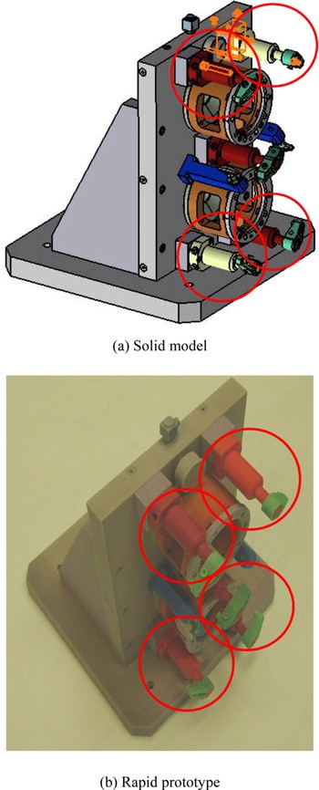
5. CASE STUDY
To validate our method, we use a fixture that holds parts to be machined in place inside a machining center as a case study (shown in Fig. 6). This fixture assembly is developed by a local manufacturer in the Detroit region. Most components are made of high-strength steel, and clamps to hold the parts are operated using hydraulics. Figure 6b illustrates a prototype of the fixture fabricated by color 3-D printing. This fixture includes four clamping arms as indicated by the four circles, which will be used to illustrate the implementation of this research.

Fig. 6. Fixture for a machining center. [A color version of this figure can be viewed online at journals.cambridge.org/aie]
Figure 7 shows form features and their relationships as related to this case study of the clamping arm. Figure 7 also includes labels for the components of the clamping arm. The clamping arm (A51) is a subassembly of the overall product, the fixture (A11). The clamping arm has nine parts; in other words, nine parts belong to (belongTo) the clamping arm. This belongTo relation is indicated as an arrow. Figure 7 displays only five parts of the clamping arm and a connecting base to increase visibility; duplicated parts are also omitted (e.g., equivalent fasteners and holes). The lines with solid circle ends indicate inter-FeatureAssociation. When the relational constraint (RCpq) is 0 or 1, a line with a single circle end is used. For example, FF71, which is the base extrusion of the cap, includes two sections of extrusion (FF78 and FF79) as shown in Figure 8. When RCpq is 2, a line with two solid circle ends is used. An example is FF11 (base extrusion) and FF12 (middle extrusion) of the base arm. These two form features are related to each other; however, one does not include the other. In this clamping arm assembly, five different types of assembly/joining relations are indicated as shown in Table 6. These assembly/joining relations are generated by joining the base arm and the connecting boss (which is not part of the clamping arm) by means of a mechanical fastening with threaded fastener, the base arm and the cap by a ring, and the cap and a fastener (e.g., fastener 1) for clamping the cap's two sections. The clamping is required to fasten the cap on the base arm. Figure 8 illustrates multiple views of the cap and it indicates a threaded fastener that connects two sections of the base extrusion (FF78 and FF79). It is of interest that this clamping of the cap uses a threaded fastener similar to the one for the arm and connecting boss. These two different joining methods are, however, geometrically very ambiguous.

Fig. 7. Form features and relationships of clamping arm. [A color version of this figure can be viewed online at journals.cambridge.org/aie]

Fig. 8. Multiple views of the cap of the clamping arm. [A color version of this figure can be viewed online at journals.cambridge.org/aie]
Table 6. Assembly/joining relations of clamping arm

In this case study, the clamping arm assembly is implemented in the developed assembly design ontology, as are the associated SWRL rules. Table 7 shows examples of SWRL rules. It also includes the facts found by ontology reasoning. The assembly design ontology is established by using Protégé 3.1, and the SWRL rule reasoning is conducted by a Rete-based reasoning engine (Bossam, 2008). As shown in Table 7, the facts clearly indicate that: FF11 (of P15) and FF101 (of P105) are joined by mechanical fastening with a threaded fastener; FF78 (of P75) and FF79 (of P75) are clamped by a threaded fastener. FF78 (of P75) and FF79 (of P75) are also related to mechanical fastening with threaded fastener. This finding is because of the similarity of rules of the two joining methods. In this manner, the joint can be successfully reasoned, and we can identify their unique morphological characteristics related to joining.
Table 7. Examples of SWRL rules and reasoned facts

The information stored in the assembly design ontology can be retrieved by the Assembly Design (AsD) Browser, developed using Java, the Standard Widget Toolkit (SWT), and the Jena ontology application program interface. The interface of the browser is shown in Figure 9. Using the interface, designers can search for assembly models that contain relevant information. Standard queries are developed based on surveys with local automotive product development engineers and are implemented in the AsD Browser. The example of standard queries include “show parts belonging to assembly X,” “show assembly relations of component X and Y,” “show directly joined components to component X,” and so forth.

Fig. 9. Ontology information browsing. [A color version of this figure can be viewed online at journals.cambridge.org/aie]
The interface of the AsD browser is shown in Figure 9. Using the interface, designers can search for assembly models that contain relevant assembly information. The browser provides three primary views of the assembly information: a geometric view of the assembly, a hierarchical view of the ontology classes, and of the properties that relate all pertinent assembly model data (Fig. 9b), and an XML view that shows the raw XML format and structure of the model data. Although the hierarchical and XML views are nontypical, they allow the user to inspect nonvisual aspects of the assembly model for such things as joining conditions and material properties. By viewing the hierarchy, users can manually determine which classes are explicitly represented in the model and their subclass relationships.
Figure 9a shows a query result by Mechanical Fastening. The browser's upper left corner displays files that include any terms related to mechanical fastening, and the lower left corner shows any notions that are semantically related (e.g., adhesive bonding, welding, etc.). Within these semantic search results, the user may make additional searches for similar items. The AsD Browser searches for relevant assembly entities by using a keyword search that examines file names as well as class structure of the associated ontology model. If the search criteria are met, the relevant assembly model returns files that contain the specified assembly information. In addition to the file results that are returned, supplementary search criteria are also displayed so that the designer may make additional searches for similar items. As shown in Figure 9a, if a designer searches for assemblies that contain mechanical fastening, additional search criteria such as welding or adhesive bonding may be returned by utilizing the ontology model because they are also joining methods, which is a result of a semantic query. Relevant terms are found by tracing the properties to related classes. In addition to tracing the explicit properties to related classes, it is possible to follow inferred properties generated by a reasoning engine.
As shown in Figure 9b, the text-based view allows the user to peruse the format in which the model will be transferred from system to system, similar in some respects to viewing the ASCII contents of an IGES file, for example. However, because this text-based information is less than ideal for user interpretation and understanding, we felt that the assembly joint design information should be visualized in an interactive way. When the user wants to know more about a particular joint, the associated assembly joint information and geometry can be conveyed by using a simulation module. We developed a system to visualize the joint's assembly/disassembly simulation based on the abstract data structure and by Web3D and Java Script. This system currently focuses on geometry visualization in an interactive way. In future research this visualization scope will be extended to topological characteristics.
Figure 10 illustrates the geometry's abstract data, which represents the relationships of an indexed face (IFijk) and indexed vertexes (IVijk l). It also includes normal vector (NVijk), indexed line (ILijm), face color (FCijk), face texture (FTijk), and line color (LCijk). This information is also implemented in the assembly design ontology and can be used for collaborative visualization. Figure 11 illustrates the simulation module where an assembly joint's geometry is visualized, and the joining operation can be simulated in a Web3D. In this module, assembly geometry is linked to the assembly design ontology based on the abstract class. The interface of the visualization module includes a 3-D display area and commend buttons for assembly and disassembly simulation. Figure 11 displays two samples of user interaction that are processed during the disassembly simulation. This simulation visualizes the motion of the cap that is detached from the clamping arm. This example shows that the geometric information of assembly, which is buried in the assembly design ontology, can be integrated into a network-based Web3D. In this manner, if the morphological assembly joint information can be retrieved and manipulated interactively in the network-compatible format (i.e., Web3D), the user's understanding for the assembly joint in design stage or other downstream product design and development stages (e.g., maintenance and training) can be significantly improved.

Fig. 10. Abstract data for geometry. [A color version of this figure can be viewed online at journals.cambridge.org/aie]

Fig. 11. Interactive disassembly simulation. [A color version of this figure can be viewed online at journals.cambridge.org/aie]
6. DISCUSSION ON REMAINING CHALLENGES
Representing the morphological characteristics of assembly joints with the eventual goal of making rational design decisions, the following challenges are still remaining.
1. The computational complexity of semantic reasoning is very sophisticated. Moreover, it requires significant time and effort to semantically represent the evolutionary, dynamically changing design data and to generate appropriate sets of decision rules.
2. Incompleteness of design information is a significant challenge for realizing a semantic framework for assembly joint design decision making. Although data completeness for an optimal decision making is clearly emphasized, we also accept that it is unrealistic to expect required design data that comes from disparate sources to be in a complete and proper structure at the time of decision. In particular, product development time is a critical requirement for a successful manufacturing company, underscoring that a decision cannot be postponed until all necessary data is obtained.
To tackle the aforementioned issues, the most appropriate minimal rules among semantic rules can be determined with computational intelligence and data mining methods (e.g., a rough set theory). However, complexity inherited by these computational methods is another barrier to realizing a successful semantic environment for assembly joint design.
7. CONCLUSIONS AND FUTURE WORK
This paper presents an ontology-based integration of morphological characteristics relating to assembly joint design. Using an ontology, various geometrically, and topologically similar joints can be successfully differentiated in a standard and machine-interpretable manner using open standard technologies. By relating concepts through an ontology rather than just defining the data syntax, assembly and joining concepts can be captured in their entirety or extended as necessary. Given that knowledge is captured in a standard way through the use of an ontology, it can also be retrieved, shared, and reused during collaboration. In our model, the geometric information is then visualized in an interactive manner. Such integration significantly improves network-based design collaborations by conveying various morphological assembly joint characteristics that are often ambiguous.
Residual stress and distortion control of joining processes in manufacturing and construction industries are considered to be key needs of the industries. To this end, various optimization and planning techniques have been investigated to understand and control joining problems. The semantically represented joints can be automatically recognized and used to formulate an optimization model. For example, a welding task sequence can be optimized to increase welding productivity and to minimize welding distortion. The authors are currently developing an integrated semantic optimization framework for welding task sequencing.
Other remaining research includes updating the ontology based on design changes. This paper focuses on a static design model. The authors are currently working to realize an interactive ontology-based assembly model for evolutionary design models. The proposed method is restricted to permanent assembly joints with zero degrees of freedom. When a certain degree of freedom is allowed, such as in a pin joint, the components' transformation and rotation should be considered in ontological modeling. Leaner information sharing is also an important issue for network-oriented product design and development. When multiple disciplines begin contributing information to an ontology-based assembly model, the amount of information may increase quickly. Not only must the behaviors of the single components/assemblies be simulated, it must also take into account the interactions of components/assemblies with other components/assemblies. This quickly becomes very complicated when components are generated by various different disciplines, and the number of components increases significantly. There is a need to determine the appropriate amount of information required to simulate a product in a network-based collaborative design environment quickly, completely, and accurately with relatively small amounts of computational power. This issue will be addressed in future research.
ACKNOWLEDGEMENTS
This research is supported by Foundation of Ubiquitous Computing and Networking Project (UCN) Project, the Ministry of Knowledge Economy (MKE) 21st Century Frontier R&D Program in Korea, and a result of subproject UCN 08B3-S1-12T.
Kyoung-Yun Kim is an Assistant Professor in the Department of Industrial and Manufacturing Engineering at Wayne State University. He received BS and MS degrees in industrial engineering from Chonbuk National University, South Korea, and a PhD in industrial engineering from University of Pittsburgh. Prior to joining Wayne State in 2005, he was Research Assistant Professor at the US NSF I/UCRC for e-Design at the University of Pittsburgh. Dr. Kim's research focuses on collaborative product development, computer-aided design/computer-aided manufacturing, and telerehabilitation, which are funded by the National Institute on Disability and Rehabilitation Research, General Motors, Ford, and Alcoa.
Seongah Chin is an Associate Professor in the Division of Multimedia in the College of Engineering at Sungkyul University, South Korea. He received his BS and MS degrees in mathematics and computer science from Chonbuk National University in Chonju, South Korea, in 1991 and 1993, respectively, and his PhD in computer science from the Steven Institute of Technology in Hoboken, NJ, in 1999. His primary research interests focus on the development of virtual human modeling. Dr. Chin has also conducted research in the area of computer vision, including feature extractions, classification, text segmentation, and object analysis.
Ohbyung Kwon is a Professor at Kyunghee University, South Korea. He received his MS and PhD degrees in management information systems at the Korea Advanced Institute of Science and Technology in 1990 and 1995, respectively. Prior to joining the Kyunghee faculty in 2004, he was a Researcher with Carnegie Mellon University's Institute of Software Research International, where his work focused on the myCampus project, which is based on Semantic Web and context-aware computing. Dr. Kwon's current research interests include ubiquitous computing services, agent technology, mobile commerce, context-aware system development, case-based reasoning, and decision support systems.
R. Darin Ellis is an Associate Professor in the Department of Industrial and Manufacturing Engineering at Wayne State University. Dr. Ellis has over 15 years of experience in the field of human factors and ergonomics, specializing in human–computer interaction. His current research is focused on human–robot interaction, including application of augmented reality to robotic interfaces, user-centered design and evaluation of robot controls and displays, operator mental workload assessment, and operator in the loop system performance measurement. Applications of this work include robotic assisted surgery (Detroit Medical Center), remote inspection via teleoperated robots (USA Department of Defense), and operation of space-based robotic manipulators (NASA).