


1. INTRODUCTION
Tangible prototypes and scale models play an important role in the design of physical artifacts. In industrial design, ergonomic, aesthetic, mechanical, and manufacturing aspects all need consideration; physical models are often used for exploration, verification, communication, and specification. Two technologies, interactive augmented prototyping (IAP)—the combination of physical and virtual artifact models through augmented reality—and rapid prototyping (RP) offer new opportunities. These technologies could improve the outcome of the design process, the creativity of the designer, and the innovativeness of the product. However, little is known about the actual application and usability of such techniques. Most evaluations are performed in educational settings, limiting the scope to product usability experiments or heuristic evaluations (Verlinden et al., Reference Verlinden, Horvath and Edelenbos2006). Even traditional approaches of model making and the roles that tangible models play in industrial design engineering have received little attention in the literature.
We performed empirical studies at design studios in various domains of industrial design engineering. By observing and analyzing design processes, and in particular the use of design representations, we aim to identify potential applications of IAP and also to determine their impact on the overall design process. This article reports on three case studies performed in different areas of industrial design, namely, the design of information appliances, automotive design, and interior design.
After reviewing some background on IAP and prototyping objectives from the literature, we present our study method. Then, each design project is described and characterized. Based on our findings we then present “hints” for future design support solutions. We conclude with a discussion of tangible design support by IAP and related technologies.
2. BACKGROUND
2.1. IAP
IAP employs augmented (mixed) reality technologies to combine virtual and physical prototypes. The underlying enabling technologies include means of display, position sensing, interaction techniques, and physical model manufacturing. In particular, the display technology for augmentation ranges from video mixing and see-through displays to spatial augmented reality in which video projectors cast computer imagery directly on physical objects (Bimber & Raskar, Reference Bimber and Raskar2005).
IAP has two principal characteristics: it enriches a physical model with digital information, and it enables interaction with these augmented prototypes.
IAP systems have been devised to support design activities in geometric modeling, interactive painting, layout design, information appliances, automotive design, and augmented engineering (Verlinden et al., Reference Verlinden, Horvath and Edelenbos2006). For example, Figure 1 shows two IAP systems to enrich a physical mockup of a mobile phone with a graphical screen: one using a head-mounted display and one using a projector.

Fig. 1. Two augmented prototyping scenarios: (top) head-mounted display and (bottom) projector-based display (Nam & Lee, Reference Nam and Lee2003). [A color version of this figure can be viewed online at journals.cambridge.org/aie]
Underkoffler and Ishii's (Reference Underkoffler and Ishii1999) URP system presented an early example of this technique in an urban planning scenario. Physical wire frames represented buildings that could be placed arbitrarily on a plane. Real-time simulations including reflections, shadows, and wind turbulence were projected on the table. The main advantage of such techniques lies in their ability to provide natural haptic/tactile feedback blended with the simulated environment. They constitute an embodied interface, allowing natural spatial reasoning while supporting social interaction in a collaborative setting (Dourish, Reference Dourish2001). Compared to traditional physical prototyping, this enrichment can display new information types (e.g., wind simulation in the example above), increase the intensity of particular types of information (e.g., material expression including texture maps), and increase the sense of engagement, which is influenced by the combination of information and its dynamic, interactive behavior. Finally, RP technologies such as CNC milling and stereolithography can be employed to fabricate the physical prototypes.
2.1.1. IAP limitations
Although it is rapidly emerging, IAP also has limitations as a tangible design medium. Constraints in physical scale and resolution of the available augmented reality displays are of key importance. At present, projector-based systems seem preferable for model inspection (Nam & Lee, Reference Nam and Lee2003) and provide more object-presence than virtual reality-based techniques such as the virtual workbench (Stevens, Reference Stevens2002). However, hollow or sparsely filled structures as well as occlusion by users present unsolved challenges for augmented prototyping.
We consider IAP as a generic, yet immature, technology that enriches physical objects in the design process. We aim to propose improvements in the design process that IAP can make possible. Future confirming studies will be required to measure the effectiveness of IAP technologies in supporting design.
2.2. The design means of physical prototyping
Surveys such as those by Engelbrektsson and Soderman (Reference Engelbrektsson and Söderman2004) and Broek et al. (Reference Broek, Sleijffers, Horváth and Lennings2000) show trends toward advanced prototyping technologies in industry, but they do not shed light on the significance of physical prototyping in design. Empirical work on the employment of physical models is mainly found in the domain of mechanical engineering. For example, Brereton and McGarry (Reference Brereton and McGarry2000) extensively analyzed mechanical engineering students' behavior and their reflections on physical modeling. They found nine physical prototyping roles, ranging from “hardware as starting point” to “hardware as a medium for integration.” Although these roles illustrate the use of tangible prototypes, they do not link particular design activities to possible applications or requirements. This line of work, extended by McGarry (Reference McGarry2005), employs contextual enquiry and observational techniques to create an extensive account of all design representations used at an engineering office. Unfortunately, the process studied by McGarry does not include physical prototypes. In a similar analysis, Yang (Reference Yang2004) compared the effectiveness of the end result and the effort and resources spent on prototyping and found no direct correspondence. Although the findings of these empirical studies are important, their application to industrial design practice is unclear. With its emphasis on shape and ergonomics, industrial design has a different prototyping tradition than engineering. Also, the complexity of real (as opposed to student) projects will influence the prototyping objectives and significance.
As a generic starting point to physical prototyping, we adhere to Geurer's (Reference Geuer1996) framework for prototyping, which identifies four main modeling intentions:
1. exploration: presenting a (modifiable) spatial geometry and supporting the form giving process (concerning global shape, specific features, and material characteristics);
2. communication: sharing the artifact's shape with other stakeholders in the design process to support decision making;
3. verification: checking whether the product design meets the design criteria and other relevant requirements;
4. downstream process specification: integrating and propagating specifications to downstream activities in the design process. A typical example can be found in the automotive industry, in which full-scale clay models act as a unified information carrier for the shape in the detailing stage.
Often, physical models serve multiple purposes; this categorization is merely meant to present the dominant drivers to employ physical models. In the following sections, we will extend this view. Discussions with design professionals and personal experience, indicated that they employ prototypes and other design representations for more diffuse and organizational purposes outside the direct scope of the product at hand, for example, to express the brand identity of a design firm, or to impress other stakeholders.
3. CASE STUDY DETAILS: PHYSICAL PROTOTYPING IN PRACTICE
The research questions and the empirical basis formulated in the introduction are stated as “how” and “why,” suggesting investigations of an exploratory, descriptive, or explanatory nature. We chose to follow the case study method. As described by Yin (Reference Yin1988), a crucial aspect of case study is combining of multiple sources of evidence (triangulation). Observations, artifact models, documentation, interviews are all consulted to establish causal relationships (see Table 1). Each case study protocol contained analysis structures, regulations, and an introductory section to explain the objectives of the project to company representatives.
Table 1. Case study analysis structure

The case studies served as a starting point to compile characteristics and specific events (“process highlights”) that influenced the design process. This body of findings was then used to identify bottlenecks or challenges that the designers faced while articulating and communicating concepts (see Section 4). In each case study, to verify the findings, the data and interpretations were presented to the main participants in a debriefing interview. These interviews were a means to triangulate the case study data. For each investigation, a case study report was made, which was again checked and approved by the designers.
3.1. Case details
The method of multiple case studies was chosen to produce a deep and accurate account of all prototyping and modeling activities (Verlinden & Horvath, Reference Verlinden, Horvath, Fischer and Coutellier2006). These cases represent a range of industrial design engineering domains. Our criteria for case selection were the following:
1. The domain should be identifiable with industrial design engineering products and processes.
2. The domains can be accessed by the researcher in terms of time, resources, and openness.
3. The selection of cases should cover a diverse range of products.
Table 2 summarizes the case study coverage. Each case study is introduced in the following format (Sections 3.2–3.4): case context: the stakeholders and the assignment; time line: tabular specification of the design process; design elements: the main focus of the design, and given and crucial elements of the artifact. Details on prototyping can be found in Section 3.5 and the following.
Table 2. Case study coverage

3.2. Automotive design: Tractor
The first case study was performed at a Dutch automotive design company, which employs four industrial designers with diverse backgrounds. Their projects range from passenger buses (both interior and exterior), specialized transportation concepts and consumer products. The company has proficiency in computer-aided design (CAD) and virtual prototyping, all performed on mobile workstations, often on-site at clients' locations. The project monitored was the redesign of the body of an imported tractor, summarized in Table 3. It covered aspects of branding, automotive styling, detailing, and preparation for manufacturing. Two senior designers shared the work between May 2006 and June 2007. The stakeholders were internationally dispersed: the client was a tractor dealer at another European country who first contacted a Dutch peer to adjust the vehicle to comply with European traffic regulations. This company contracted a manufacturer for the body shells, who subsequently hired the design studio. Most communication was by e-mail, although some meetings occurred when a milestone was reached.
Table 3. Tractor design time line

In this assignment, the motor compartment cover (the body) and related aspects such as the dashboard and paneling around the seating was most important. The design focuses on the body, in particular, the shape, construction, and material properties concerning aesthetics. As the tractor is a slow agricultural vehicle, traffic safety issues were of less importance.
3.2.1. Design elements
Figure 2 shows the design elements in the tractor design case study. The design is constrained by the given elements: the chassis and the engineering package. These define shape boundaries; the body also must accommodate the movement envelope of the engineering package and related components (wheels and related parts). The crucial design elements are those elements that are obligatory parts but variable in shape and behavior. Air inlets are necessary to cool the motor, but their area and placement on the hood depend on the overall shape and performance. Headlights are obligatory for European rules, whereas the dials and steering are defined by the original (Chinese) design but can be adapted in styling.

Fig. 2. The design elements of the tractor design case study.
3.3. Information appliance: Hand-held oscilloscope
Finding a representative information appliances case proved difficult, as most developing products are shielded from competitors and external observers are not allowed. Therefore, we performed a retrospective analysis of a handheld digital oscilloscope.
The project involved developing new technologies for fast analog–digital conversion, an updated form factor for the brand, and a good fit with market and use (Table 4). This second case study was performed at a Dutch design office of an international electronics design and manufacturing company. Product development occurred between 1996 and 1999, so we adapted our case study for an historic analysis.
Table 4. Oscilloscope design time line

The development team represented various disciplines, including industrial design, user interface design, product planning (product marketing), core technology research and development, sales, mechanical engineering, software engineering, electrical engineering, factory engineering, and packaging. Most stakeholders were employees. The resulting product is regarded as one of the best in the market: it won several design prizes (IF Design award 2000) and subsequent diagnostics products for the brand still use an identical form factor.
3.3.1. Design elements
Figure 3 shows the design elements for the oscilloscope design. The oscilloscope body can be viewed as the element that bridges all design and engineering aspects. The design focus of the body corresponds with industrial and interaction design, reflected in shape, behavior and material properties concerning aesthetics, ergonomics (both physical and cognitive), and production. Although the electronics parts (engineering package) also received a great deal of attention during development, for this investigation we viewed the engineering package as given, as the electronics parts do not directly influence the product manifestation.

Fig. 3. The design elements of the hand-held oscilloscope case study.
Three design elements (probes, display, buttons) required extensive exploration and influenced the design of the body. We considered these crucial design elements.
• Probes: Touching contacts and picking up electric signals is of crucial importance. Thus, the user should be able to shift between various tips and clamps. The device can monitor two signals simultaneously and two electrical contacts are necessary for each. Over 20 different probes with different tips and voltage ranges are shipped with the final product.
• Display: When this product was developed (1996–1999), one could not simply select liquid crystal display screens from a catalog. This not only influenced product cost and development effort for electrical engineering but also the visual characteristics of the screen (field of view, contrast, resolution, color capabilities) as well as the size and weight. Later versions were shipped with a 320 × 240 pixel display.
• Button layout: Selection, placement, and size of the keys were of primary concern. The final design has 35 buttons, some with fixed and others with flexible functions.
3.4. Interior design: Museum
The third case study was carried out at an office of a well-known Dutch furniture designer, which employs approximately eight people from a fine arts background. The head designer emphasizes innovative approaches to furniture design. The project monitored was the interior design and specialized furniture of a municipal museum in The Netherlands (Table 5). Three designers shared the work from October 2006 until the museum opened in 2008. We followed the process until May 2008, when the detailing phase was completed. There were many external stakeholders of the projects, including its director, curators, local government, and restaurant keeper. The director is the key decision maker who controls the budget and manages practical issues. The curators have most influence on the interior, as they are in charge of launching exhibits that attract the public. The local government officer is responsible for funding and building regulations; the restaurant keeper has a limited role, concerned with the logistics of serving food and drinks. These stakeholders have little experience in design projects as they happen infrequently.
Table 5. Museum interior design time line

3.4.1. Design elements
The assignment was to design the museum's interior, in particular, the layout of the space and furniture to host particular functions, for example, counter, restaurant, and museum shop. The given element is the building: the constructed walls, a centrally located staircase and the façade. Although the landscape surrounding the building is not owned by the museum and could be considered as given, the design studio took it as part of the design assignment (Fig. 4).

Fig. 4. The design elements of the museum interior design case study.
The museum interior must be flexible and should easily adapt to different exhibits and special events (the original proposal was titled “art parking”). The events proposed were: child's atelier, exhibit, architecture café, lecture, dancing, auction, and workshop. Crucial design elements that might move or transform were artwork (pieces on show, paintings, sculpture, etc.), the wardrobe, counter, and shop.
The main design focus was the distribution of spatial functions in the museum. This differentiation of zones relates, on the one hand, to events at the museum (ticket sales, receptions, child's visits, etc.). In contrast, spatial functions correspond to one or more physical zones in the building, which might change or move when necessary. Among the most prominent items is an “accordion space,” which grows or shrinks with one moveable wall. Of course, the constituents of the design focus and crucial design elements are not static: some functions were adapted (office space as a mobile element or a fixed zone), whereas others were introduced during the process (notably the garden and mobile kiosk).
3.5. Prototypes
All three projects used physical models for several purposes (summarized in Table 6). In addition to prototype characterizations, we determined the number of prototypes made, the lead, lifetime, and the impact on the overall design project as reported by the chief designer. (Appendix A lists all of the physical prototypes.) Prototypes made for exploration and verification were used internally mainly to support group discussions and brainstorming sessions, except C1.2, which was employed by only one individual. Tangible prototypes for communication were mainly available during design review meetings, and in both cases they remained in close proximity of the project lead during other activities. This promoted awareness of the project and its progress to internal and external collaborators.
Table 6. Physical prototyping objectives among the three cases

The numbers in parentheses refer to the indices in Appendix A.
The tractor design project employed few physical prototypes (Fig. 5), characterized in Appendix A as C1.1 to C1.3. As the design studio is committed to using the CATIA digital modeling application, there was no prototyping budget. The CAD application allows considerable freedom in fine-tuning the shape and in meeting all fitting constraints that were prevalent in this project. Furthermore, the digital model was thought to act as an ideal interface between design and manufacturing (CNC milling). However, in one interview, the designer claims that including more scale or full-size mockups could have helped determine and communicate the physical manifestation of the product.

Fig. 5. The tractor physical models: (left) an elongated tractor chassis that was reverse engineered and (right) a wooden impression of a hood to select and place car headlights in the new geometry. [A color version of this figure can be viewed online at journals.cambridge.org/aie]
The oscilloscope design project can be characterized as a typical human-centered design project. It featured usability engineering techniques such as concept testing in focus groups, paper prototyping, and virtual prototyping evaluation on PCs with physical mockups attached (Verlinden et al., Reference Verlinden, Suurmeijer and Horvath2007). A main weakness of a sketch prototype (C2.1 foam mockups) is that it does not support exploration of the graphical user interface and interactive behavior; the user interaction prototype (C2.2) had an extremely long lead time and was not easily adapted.
In the museum interior design project, four models were made (C3.1–C3.4), all with paper and foamboard using prints of scale drawings made in VectorWorks. From the start, the studio's proposals also dealt with the building exterior. Although this is not formally part of the museum, solutions were proposed to expand the atmosphere of the interior.
In the final model not all walls were physically modeled, only those parts that contributed to understanding the conceptualized functional spaces. At such reduced scales, it is challenging to get a correct impression of space. Furthermore, all models were monochrome, to focus attention on the conceptual solution and not on materials, colors, or the like. In the words of the head designer, the colored human scale dummies shown in Figure 6 “radiate their color and vividness to the remainder of the design.”

Fig. 6. Scale model detail, showing a colored man dummy in monochrome design. [A color version of this figure can be viewed online at journals.cambridge.org/aie]
3.6. The impact of prototypes
According to the designers, the impact of the prototypes varied. In the tractor case the physical prototypes had a minimal impact, whereas in the oscilloscope and museum interior cases they had a substantial impact on the project.
The opinions and reflections of the designers when presented with the case study results reveal factors that support the inclusion of physical prototypes in practice: prototyping tradition, ease of physical reproduction of a product, the need to evaluate the design with end users, skills and attitudes of stakeholders, and leadership in decision making.
Some studios relied on physical prototyping; others adopted digital tools (e.g., in the tractor case). This also shapes the facilities that the studio hosts for prototyping activities. In addition, some products are difficult to model physically, a function of shape and intended scale. In the tractor design case we expected the use of small-scale models as is common in the automotive industry for exploration and communication (Tovey, Reference Tovey1997). However, this did not happen. The other two design projects more or less resemble common practice in their respective domains of hand-held information appliances and interior design. The human-centered approach of the oscilloscope case implied the need to evaluate with end users, whereas the other two had different stakeholders and concerns to address. In addition, in both the oscilloscope and museum interior cases, physical models addressed limitations in the spatial reasoning skills and differing attitudes of the stakeholders in the design process. Finally, strong decision-making leadership implies the need for multiple, tangible design alternatives that can be put on the table during and between discussions. Only for the oscilloscope design was a substantial budget reserved for prototyping. The complete dependencies of physical prototyping inclusion are depicted in Figure 7.

Fig. 7. The influences to include physical prototypes in design processes based on the cases.
4. HINTS FOR IAP
The previous section reflected on current design practice to address the why and how questions specified in Table 2. However, this characterization does not necessarily point at new means of design support. We examined the case studies to identify problems that IAP could have eased and by identifying best practices that such solutions support.
4.1. Hints
The problem of devising IAP solutions to support the investigated cases is twofold. First, IAP is a developing approach that is not yet committed to specific functions or representation types. Second, the nondeterministic nature of the design process makes it difficult to apply traditional methods of distilling functional requirements from observations. Therefore, we devised an alternative to a standard requirement called a “hint” (see Table 7). A hint is a situated solution that an IAP solution can provide. It embodies pointers to particular design support scenarios that could relieve bottlenecks or that implement a best-case solution. Hints are grounded by specific findings in the case study database. Therefore, the hint is speculative and the underlying evidence determines its qualities: it resonates with the didactical concept of “hints” harboring both partiality and imprecision (Horacek, Reference Horacek2003). Kolhas et al. (1993) provide a probabilistic backdrop to reason with varying degrees of support in the theory of hints. The description of a hint points at an IAP usage scenario, which can be supported by a collection of implementations.
Table 7. Hint density: Number of relevant process highlights per case
We do not want to constrain discovery of hints by the prototyping objectives and roles that we found in the literature. Indeed, IAP might be better equipped to solve problems that are unrelated to the prototyping objectives and roles. The bottlenecks mentioned in Tables 4 and 6 indicate how the collaborative aspect of design introduces multiple interpretations and value systems of “performance” or “bottlenecks.”
4.2. Procedure
We derived bottlenecks and best practices using the explanation building technique, to “stipulate causal links of a phenomenon” (Yin, Reference Yin1988, p. 113). As indicated in Table 2, the main sources of evidence for the bottlenecks are interviews and observations. This procedure for hint discovery resembles the closed coding strategy of grounded theory (Glaser & Strauss, Reference Glaser and Strauss1967). The first author annotated the interview transcripts of all cases using the ATLAS.ti (www.atlasti.com) tool. Per case, these process highlights were aggregated to result in collections of unique bottlenecks or best cases. Then the resulting highlights were collected in one database.
The second step devised ways to translate the resulting highlights to IAP scenarios. Sometimes, the case study participants suggested IAP functions that were then added to the hints. New scenarios were generated by scanning all highlights while considering the possible benefits of IAP as specified in Section 2.2. Finally, the hints were grouped and formulated as scenarios.
4.3. Results
This section presents the resulting hints, spanning six groups (A–F). Table 7 indicates the density, or number of occurrences in the case study materials, of process highlights that suggested each hint.
Hint category A: Enrich the product with information that is difficult to achieve in other ways
Hints in this group indicate enhancements of a design representation by means of IAP. These appeared in each of the design processes, as described below.
Hint A1. Inspire and promote lateral thinking by using unexpected, random information. In the tractor design case there were issues in conveying the style variation among the concepts. Alternative designs were rendered as three-dimensional (3-D) images without context (approximately six slides per concept). This issue was later addressed with sketchy renderings that emphasized principal styling curves and differentiating aspects of the designs (see Fig. 8). The second version embedded these in a presentation that included archetypes of specific designs (e.g., the title “Edgy” and images from BMW sports cars). Providing one or more scale model prototypes with projections of styling and contextual information (text, images) nearby would have been useful. A single 3-D printed model could be augmented by each of the three alternatives.
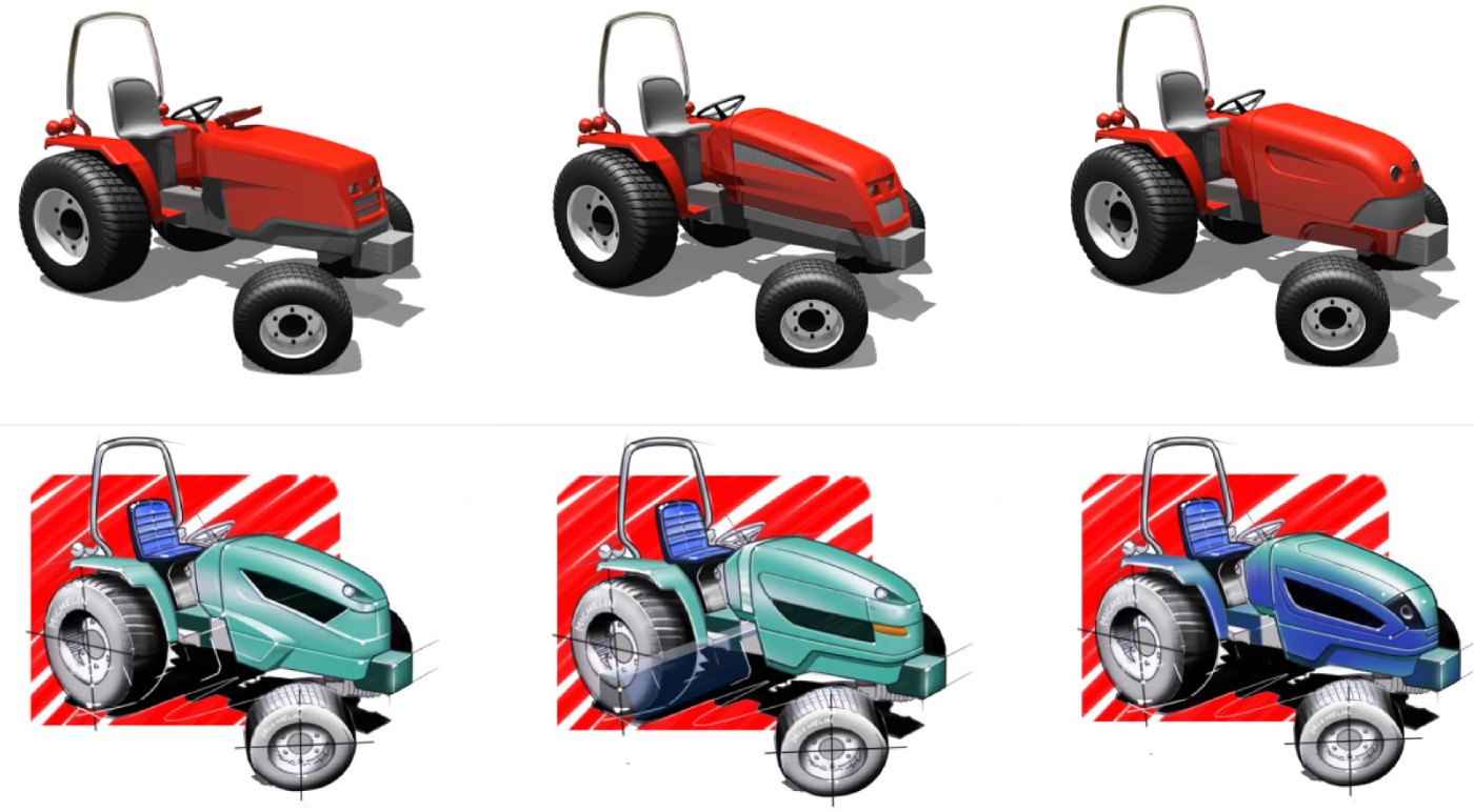
Fig. 8. (Top) First and (bottom) second concepts of tractor design. [A color version of this figure can be viewed online at journals.cambridge.org/aie]
In the oscilloscope case, a wide range of competing and archetypical electronics measurement products was considered. These could be put into an image database and projected on foam mockups to visualize them.
Hint A2. Simulate shape and GUI navigation. In the oscilloscope case it was difficult to combine the physical product design and the interaction design (i.e., navigation, graphics, and button operation). Despite attempts to combine them, these design activities were too separated and the interaction design was suboptimal and required tuning after the null-series products were manufactured. By combining the digital graphical user interface (i.e., screens) with physical shapes, the navigation structure and button operation closely resembled the behavior of the final design.
Hint A3. Explore color and material. In the museum case, there was some confusion regarding the use of curtains. An animated representation of the curtains could have expressed the designer's intentions in using reflections and transparency and possibly basic colors projected in the floor plan.
Hint A4. Simulate shape and behavior at same time (automatic, i.e., pedestrian flows). In the interior design case, the usage scenarios were difficult to express; interactive pedestrian flows would have helped in exploring layouts and presenting ideas. Applications such as URP (see Section 2.1) and Mousehaus Table (Huang et al., Reference Huang, Do and Gross2003) have demonstrated simulations combined with tangible models.
Hint A5. Overcome the threshold to work with one medium only (richness in media, tangibility). The design studio that worked on the museum had a tradition of employing a wide range of materials to make prototypes, enrich the design process, and get inspiration from the media (see also Fig. 9). This could also be applied to IAP.
Hint category B: Enable fitting (functional) components or so-called engineering packages in freeform global shapes
In both the tractor and oscilloscope cases, designers had to deal with the relationship between external shell and internal parts or engineering packages, while at the outer surface locating components for interaction with users or the environment.

Fig. 9. Furniture-scale models made from different materials in the museum case. [A color version of this figure can be viewed online at journals.cambridge.org/aie]
During the detailed development of the tractor design, a big challenge was selecting and fitting headlights. As the body width was slim, two regular car headlights could barely be placed inside, especially because the engineering package inside extended in all directions and left space only for air inlet/cooling. After selecting a small, not too expensive car headlight, the geometry had to be recreated in the CAD system. For a final check, a set of wooden section views was made. The freeform shape also had to be changed significantly to fix discontinuities.
A similar concern arose during the design of the oscilloscope. Trade-offs between the outside housing and the buttons required constant attention, and the envelope of the embedded electronics also changed several times, which influenced button and screen placement. In the interior design case, the global shape was flat; yet as certain building elements were given (supporting walls, stairs, windows), the designers faced a similar challenge. Improvised scale furniture was made in different materials and placed in the floor plan.
These activities could benefit from IAP according to hints B1–B4.
Hint B1. Search for components that fit in (geometric) design. Existing component databases on headlights or buttons could be imported to the CAD system or transferred to a physical model.
Hint B2. Reverse engineering of shape. For the headlight selection, outsourced reverse engineering services were retained to convert a physical shape to a digital model. Using a projector–camera system, an IAP system could convert the physical shape to its geometrical data (Kim et al., 2005).
Hint B3. Fit fixed components in freeform shapes and engineering package. Using a mixture of physical and digital components, the designer can interact with the most determining elements by hand as secondary elements are displayed.
Hint B4. Correct tactile sensation of look and feel of physical interaction. In a graphical user interface (GUI) interaction modeling environment, it should be possible to use several buttons, switches, and so forth to tune the look and feel of the interaction behavior.
Hint category C: Ease global shape creation and layout studies
The physical models of the hand-held oscilloscope enabled fast creation of product variants. These were used to determine overall dimensions, grip, screen size, and button layout.
Table 8. Definitions of the case study variables

Hint C1. Start with manual physical shape creation. The oscilloscope models were made by hand. IAP technology might have helped speed the manufacturing of these models by presenting building/cutting/measure guides and simultaneously creating a digital record of the resulting shapes.
Hint category D: Design review
In all three processes, design review meetings were of key importance, as they set the stage for discussions with all stakeholders and for decision making. The design review meetings had a similar structure: a presentation of progress by members of the design team was followed by a discussion of concerns and issues. Then other experts from marketing and manufacturing gave progress reports; finally, documents were approved or amended and an action list was revisited. In the tractor design case, unstructured design reviews and long communication delays often hampered communication. The oscilloscope design project frequently organized intermediate design review meetings in which updates were discussed. A prominent item was the shape design and presentations of client visits to address key functions, concerns, and so forth. In the museum interior case, design review meetings were scheduled monthly. As Table 8 reveals, most models were indeed created to support design review sessions, and several hints emerged to support these by IAP.
Hint D1. Provide better insight of a shape for an untrained client. As mentioned in discussing hint A1, during tractor design meetings the manufacturer and client had difficulties understanding the shape and intended style. No physical models were made and, although the presentation material was sent to all stakeholders, these digital files were not always sufficiently expressive. Using IAP, inexpensive physical models can be manufactured rapidly that represent the shape only globally, whereas the digital model expresses detail. Second, the physical-only scale model of the museum interior makes it difficult to experience space. This could be addressed by connecting a virtual walk-through of the model as a tangible interface, as demonstrated by the BUILD-IT system (Rauterberg et al., Reference Rauterberg, Fjeld, Krueger, Bichsel, Leonhardt and Meier1998).
Hint D2. Align ideas and concerns concerning design alternatives. Unlike flat pictures or descriptions of design proposals, physical models allow spatial reasoning and interaction by all stakeholders. Pointing and drawing directly on the object's surface establishes fluent interaction, as demonstrated by the Dynamic Shader Lamps system (Bandyopadhyay et al., 2001). Elaborate pen-based annotation facilities (Tsang et al., Reference Tsang, Fitzmaurice, Kurtenbach, Khan and Buxton2002) could also enhance this activity.
Hint D3. Improve recording and accessing design reviews. Minutes of review meetings did not always capture all concerns or positions of the stakeholders regarding controversial design alternatives. In the tractor design case, the client mentioned the issue of headlight selection at the initial session, yet it took considerable time before the other stakeholders understood this position. In the museum interior design case, other stakeholders did not discuss decisions concerning the use of space, whereas these were of primary interest for the design studio.
IAP could facilitate this recording and recollecting in several ways, for example, by capturing interaction with the prototype and logging the participants' discussion. The spatial activity could index navigation through decisions. Such facilities could be easily extended by annotation tools, and recording other activities of a design review such as presentations. A formal design review recording method as developed in Huet et al. (Reference Huet, Culley, McMahon and Fortin2007) can support this.
Hint D4. Steer away from preoccupations of stakeholders and focus on aspects of key importance. In the museum interior design project, stakeholders were sometimes preoccupied with the detailed shape and aesthetics and overlooked function. Likewise, in the tractor design case, much effort was made to vary construction principles, whereas the client was focused only on creating a new style. In the museum interior case, this issue was addressed by equipping physical models with only partial details, omitting most walls, and including sketchy versions of certain furniture items. Some components were fixed to the floor plan, and others could be rearranged. This common solution highlights a property of physical representations that is often overlooked, namely, the restrictions and the emancipatory power it offers as a social interface.
IAP could assist in selecting what details to prototype, and to keep certain aspects fuzzy while rendering others crisply. Animations, related texts, and other representations could help in achieving an appropriate level of fidelity.
Hint category E: Create better insight of the product and process to other stakeholders (not necessarily during meetings)
The persistence of physical objects creates an awareness of the project beyond formal meetings, allowing peers and external participants to track the latest developments and the project's history.
Hint E1. Create insight in project progress. The oscilloscope project used a table to display all the physical models and drawings from the involved disciplines. This enabled stakeholders to stay informed about changes and also established an attractive exhibit for future clients. Physical models were made of several materials, which provided richness. This notion could be extended to IAP-based tables as shown in the Virtual Showcases (Bimber, Reference Bimber2002), allowing more elaborate display of the design process, possibly while limiting outsiders' access to sensitive information.
Hint E2. Attempt to broaden the assignment to peripheral design tasks. Similar to hint D4, elements can be included in the prototype that are not part of the official design brief, for example, the landscape design of the museum garden and transportation facilities. This resulted in several discussions of the surrounding area with regional authorities and also in the design of a mobile exterior unit. The physical prototypes were the main vehicles to address these issues to external stakeholders. The initial mockups of the handheld oscilloscope included proposals for the GUI design, as invented by the industrial designers (not the interaction designers). IAP could offer similar facilities as in hint D4 to support such activities.
Hint category F: Use(r) studies
In only one case (the oscilloscope) were user studies and usage evaluation experiments carried out. In the museum interior, there was no awareness. In the tractor design, the use of the product was not evaluated other than heuristically reviewing the design requirements. In contrast, the oscilloscope design included over 150 user visits to evaluate early products and to obtain user profiles, task analyses, and market characteristics.
Hint F1. Executing and presenting results of user studies. During the oscilloscope design development, a PC-based mockup was made to test and elaborate parts of the graphical user interface (C2.2, Appendix A). This took a substantial amount of time, and did not represent the full shape/weight of the design. Hint A2 covered the facilitation to make such a working physical model, which can simulate GUI interaction and capture user performance.
Hint F2. To access prospective users (conversation piece). As one participant in the oscilloscope project noticed, prototypes functioned as an easy entrée to users who otherwise might question their incentives in collaborating in the product development process.
4.4. Hint summary
Our investigation focused on a range of industrial design projects that could illustrate prototyping objectives and deepen existing knowledge about the facilitation of these physical representations of the design process. The objective was to align the technology affordances of IAP with these processes and to identify possible design support scenarios. Several tasks or actions in the design process can be facilitated, both in modeling and communication. Table 9 gives an overview.
Table 9. Aggregated IAP hints as found in the case studies

5. DISCUSSION
5.1. Findings
The hints represent interesting directions for supporting design with IAP. However, several concerns about IAP capabilities and limitations should be addressed: coding protocol, information sources, and the coverage of three different design domains.
5.1.1. Coding protocol
The coding protocol used an associative reasoning model to identify hints. However, this activity is prone to subjectivity and implicit knowledge of IAP. We tried to minimize this effect by formalizing the procedure for highlighting and hint creation; it was not feasible to validate hint finding by multiple coders, as the interview transcripts totals over 700 paragraphs.
Several issues surfaced that could not be linked to the IAP support scenarios. These include the following:
• Organizational issues: unclear project structure, parttime involvement, infrequent meetings, budgeting, and design requirement setting
• Decision-making issues: the dominance of the client, the designer not being taken seriously by the manufacturer, the client not being taken seriously by the designer, a slow decision making pace
• Team functioning issues: lack of leadership in the design project, initial hesitation from engineers to work in interdisciplinary teams
5.1.2. Information sources
The main source of information was the interview data. As discussed before, the interviews served to triangulate the observations and interpretations from other data sources such as the design representations (sketches, models) and documentation (design review meeting minutes, planning). In addition, most interviews were carried out with designers, not other stakeholders, because we consider the designers as the prime users and potential beneficiaries of IAP.
5.1.3. Coverage of three design domains
In the debriefing interviews, designers were asked whether the project was representative of their design domain. All answered affirmatively, although the tractor design project was considered different both in its manufacturing process of agricultural vehicles and by having a client abroad with indirect communication. By nature, all are different, but the process highlights overlap in terms of bottlenecks and best practices. Furthermore, by identifying the design elements for each case, all projects have a design focus, given constraints, and crucial design elements that can be mapped to IAP systems.
5.1.4. Measuring the design means of a tool
The impact of the physical design means is difficult to determine in a single characteristic. Apart from utilitarian purposes, physical design supports shared understanding or insight. In searching for a reasoning model to support our early findings, we found the extensive work on Critical Systems Thinking by Jackson (Reference Jackson2000), which to our knowledge, has not been applied in the field of engineering design. The only similar work we found focuses on interior architecture of public spaces (Mobach, Reference Mobach2007). We propose that this framework expands traditional reasoning on prototyping to a platform for judging the impact of advanced tangible prototypes on the design process.
6. CONCLUSIONS
In industrial design, physical prototypes can be used for exploration, simulation, communication, and specification (see Table 8). To obtain insight into current prototyping practice, we carried out three case studies in different design domains (interior, automotive, information appliances). Our case studies demonstrate various instantiations of tangible models, which as physical entities are not used solely to provide insight but also to influence decision making and to seduce other stakeholders in the design process. Based on our aggregated findings, the inclusion of physical models in current practice depends on studio (prototyping tradition and availability of facilities), product (scale, shape, need to evaluate with end users), and stakeholders (skills and attitudes of stakeholders, leadership in decision making).
When considering the inclusion of tangible computing and augmented reality as means of design support, the case studies suggest specific activities and situations covering both modeling and communication. In modeling, these include enrich the product with information that is difficult to achieve in other ways, enable fitting of (functional) components or so-called engineering packages in freeform global shapes, and ease global shape creation and layout studies. In communication, the hints include design review, create better insight of product and process to other stakeholders (not necessarily during meetings), and use(r) studies.
Finally, the assessment of the impact of new prototyping technologies should consider multiple paradigms, as the design process inevitably bears multiple perspectives. Our interest has been drawn to the critical systems thinking approach of Jackson (Reference Jackson2000), which originates from the field of organizational sciences and considers functionalist, interpretive, emancipatory, and postmodern stances. This approach could be successfully applied to highlight and compare bottlenecks and best practices concerning concept articulation in the three case studies.
ACKNOWLEDGMENTS
The authors express their gratitude to Guest Editors Ellen Yi-Luen Do and Mark D. Gross for their continuous assistance and support. Part of the material in this article was presented in 2007 at the 3rd International Conference on Advanced Research in Virtual and Rapid Prototyping.
Jouke Verlinden has been an Assistant Professor in the Department of Computer Aided Design Engineering at Delft University of Technology since 2000. He received his MS in computer science in 1993 and has a background in interactive computer graphics and virtual reality. He worked in industry as an Interaction Designer and Project Manager for 7 years before returning to academia. He is currently working on a project entitled “Augmented Prototyping as a Design Means for Industrial Design Engineering,” which encompasses both empirical research and system development. The ambition is to develop new, accessible design media for industrial designers that respect current practice.
Imre Horváth has been a Professor of computer-aided design engineering at Delft University of Technology since 1997. He held various positions in industry and academia between 1985 and 1997. He received an MS in mechanical engineering in 1978 and an MS in engineering education in 1980 from Budapest University of Technology. He also earned a DrUniv in 1987, a CDSc in 1993, and a PhD in 1994. Dr. Horváth initiated the International TMCE Symposia and is Co-Editor in Chief of Journal of Computer Aided Design and Associate Editor of Journal of Engineering Design. His primary research interests are in methodology of design research, advanced computer support of conceptual design, and tangible virtuality.
APPENDIX A
Exhaustive list of physical prototypes of case studies


