NOMENCLATURE
-
 $X_{i}$
-
Pseudo density
-
$\rho_{i}$
-
Density of the i th element
-
$\rho_{0}$
-
Density of the base material
-
$E_{void}$
-
Very low Young’s modulus
-
$E_{solid}$
-
Young’s modulus of solid regions
-
$E_{(xi)}$
-
Young’s modulus of each element
-
$V$
-
Total volume
-
$V_{i}$
-
Volume of the i th element
-
$V_{0}$
-
Initial volume
-
$F$
-
Force vector
-
$U$
-
Global displacement
-
$K$
-
Global stiffness matrix
-
$k_{0}$
-
Elemental stiffness matrix
-
$f$
-
Distributed body force
-
$u$
-
Displacement area
-
$t$
-
Traction force
-
$F_{i}$
-
Point load on the i th node
-
$U_{i}$
-
i th displacement degree of freedom
-
$S$
-
Surface area of the continuum


1.0 INTRODUCTION
The aviation industry and its related markets are expanding widely due to increased air travel customers. Engineers and researchers in the aerospace field have been investing substantial effort in producing advanced aircraft with high performance capabilities to accomplish efficiently its mission requirements under various flight conditions(Reference Torenbeek1). Presently, the main concern of engineers around the world is to produce new-generation aircraft through research and innovative technologies with the aim of increasing performance and decreasing ecological impacts. Morphing structures are considered to be successful techniques for achieving these objectives.
An effective example is the Adaptive Trailing Edge Device (ATED), which was designed in the Smart Intelligent Aircraft Structures (SARISTU) project coordinated by Airbus, aimed to improve aircraft performance by reducing fuel consumption by up to 5%(Reference Diodati, Ricci, De Gaspari, Huvelin, Dumont and Godard2-Reference Arena, Concilio and Pecora4).
In the aviation industry, efforts are currently being exerted to produce a new generation of aircraft that can achieve a 50% reduction in aircraft fuel consumption and CO2 emissions by 2020 while ensuring safety. Such objectives have driven engineers to reduce aircraft weight by using new design technologies involving optimised composite materials, morphing wings and others(Reference Zhu, Zhang and Xia5,Reference Tchatchueng Kammegne, Grigorie and Botez6) .
Topology Optimisation (TO) is one of the most important structural optimisation methods and is applied to determine an optimised material distribution over a given design space and thereby reduce the weight of an aircraft(Reference Rao, Kiran, Kamesh, Padmanabhan and Chandra7). Thus, the best structural load distribution is found using this method(Reference Zhu, Zhang and Xia5,Reference Mitropoulou, Fourkiotis, Lagaros and Karlaftis8) .
Various optimisation techniques have been applied in engineering design over the years, and their use has been increasing in the aerospace domain(Reference Krog, Tucker, Kemp and Boyd9). Engineers have used TO to design individual aircraft components, such as wing and fuselage elements(Reference Eves, Toropov, Thompson, Gaskell, Doherty and Harris10). Airbus used TO methods to find the shapes of new components needed to reduce the weight of the A-380 aircraft. The most well-known example of successful application of such optimisation is the Airbus A-380’s leading-edge ribs alongside the fuselage door intercostals, achieving a weight reduction of approximately 1,000kg(Reference Grihon, Krog and Hertel11). Another interesting project was carried out at Boeing to design the wing’s leading-edge ribs for its B-787 Dreamliner aircraft. It integrated TO with sizing and shape optimisation, which led to a reduction of the weight of the B-787 leading-edge ribs by 24–45% in comparison with those of the B-777 aircraft(Reference Wang, Lu and Zhou12,Reference James, Kennedy and Martins13) . At Bombardier, engineers investigated the aerodynamic design loads for wing-box rib by using two-dimensional TO(Reference Buchanan14).
Oktay et al.(Reference Oktay, Akay and Merttopcuoglu15,Reference Oktay, Akay and Sehitoglu16) carried out estimation studies on the material distribution optimisation of an aircraft wing using TO tools. Coupled Computational Fluid Dynamics (CFD) and a structural optimisation solver were used to reduce the overall aircraft weight.
The Finite Element Method (FEM) and TO have been considered to represent significant tools in the aircraft design area(Reference Ramesh, Handal, Jensen and Rusovici17). Integrated application of FEM and TO for an aircraft can result in a significant weight reduction, thereby saving material costs without impacting the final model’s robustness or strength properties(Reference Tang, Xi, Zhang and Hu18,Reference Gawel, Nowak, Hausa and Roszak19) . The optimisation processes achieved by combining CFD with Computational Structural Mechanics (CSM) result in the determination of a wing shape with optimal aerodynamic performance in all operational flight conditions while keeping its minimum design weight(Reference Morlier and Charlotte20).
The present study provides a novel vision-based structural analysis and TO for a MVSTW design based on the NACA 4412 aerofoil. The optimisation was implemented to effectively locate the wing components (spars, ribs, stringers and others) within the wing sections, based on the TO method. Candidate materials were then selected inside the design domain of the wing. The material constraints, such as the volume of a structural design, significantly affect the mechanical properties, such as the total stiffness and robustness(Reference Plocher and Panesar21). The TO method improves the wing structural design by finding the most feasible structural layouts for its different structural components(Reference Zhao, Li, Chang and Li22). The positions of the wing elements must also provide the maximum rigidity to the overall structural configuration of the wing(Reference Zhao, Guo, Duan and Xing23).
The previous part of this study investigated the aerodynamic performance of the MVSTW by studying the effects of changing the sweep angle on the morphing wing by varying its span extension (to 0%, 25%, 50% and 75% of its length)(Reference Elelwi, Kuitche, Botez and Dao24). That analysis was carried out at different speeds, representing all of the flight phases. The wing shape with the best aerodynamic efficiency was selected for this TO study. The wing shape chosen consisted of two parts, a fixed part and a moving part, while both axes coincident. This TO of the MVSTW aims to improve the structural performance of the wing in all flight conditions and span extensions while reducing its weight.
2.0 DESIGN AND MODELLING OF THE MVSTW MODEL
Many studies have shown that an aircraft with a morphing wingspan can perform in different missions(Reference Elelwi, Kuitche, Botez and Dao24). For example, an aircraft with a large wingspan exhibits enhanced aerodynamic efficiency, characterised by a flight range increase, as well as decreased fuel consumption. In contrast, an aircraft with a small wingspan can offer higher flight speeds and better manoeuvrability(Reference McCormick25). The asymmetric telescopic wingspan technique can be employed for roll control instead of using conventional control surfaces(Reference Gao, Jin, Zhao, Cai and Zhu26,Reference Chen, Guo and Wang27) . However, the constant challenge facing designers regarding variable span morphing wing design is to overcome the weight penalty as well as its design complexity(Reference Barbarino, Bilgen, Ajaj, Friswell and Inman28). The TO method is one of the approaches for reducing the structural weight without affecting the strength properties of the wing.
The wing shape model selected at this stage from the MVSTW project was finalised at our LARCASE laboratory and includes two models based on the results obtained by aerodynamic analysis(Reference Elelwi, Kuitche, Botez and Dao24). These results showed that the first model is more efficient than the second. The solid wing models for both segments were designed using Computer-Aided Design (CAD) with CATIA software. The TO method was then carried out based on the aerodynamic analysis results for the selected wing shape using a CFD solver. After obtaining the wing TO results, its components were designed and distributed inside both sections. The final wing shape was validated by using the FEM code.
A variable-span morphing wing was designed using the telescopic mechanism concept. Both segments of the morphing variable span of the tapered wing were designed based on a NACA 4412 aerofoil shape(Reference Communier, Botez and Wong29). The wing was divided into two sections, as shown in Fig. 1.
Table 1 Wing parameters at three modified wing spans and the original length

Table 2 Wing parameters for fixed and moving segments


Figure 1. Geometrical shape of the variable span of a tapered morphing wing.

Figure 2. A variable morphing span at various lengths: (a) original position, (b) 25%, (c) 50% and (d) 75%.
The selected model was designed such that the central axis line of the moving segment coincided with that of the fixed wing segment. In addition, the inner wing was positioned within the fixed wing at a swept angle of 4.5°. The geometrical parameters of the wing sections are presented in Table 1 (for MVSTW) and Table 2. Table 1 shows the main parameters of the variable morphing wing for four different span lengths, while Table 2 lists the main parameters for the fixed segment, and the moving segment.
In the previous study, the aerodynamic investigation was performed(Reference Elelwi, Kuitche, Botez and Dao24) for wings with different span-wise extensions, viz. 25%, 50% and 75% of the original position as shown in Fig. 2. Different span extensions were studied for the Hydra Technologies’ UAS-S4 wings with the aim of achieving multiple missions within a single flight(Reference Elelwi, Kuitche, Botez and Dao24). The selected speeds were 17, 34, 51 and 68 m/s, representing the minimum, loiter, cruise and maximum speed, respectively. Furthermore, aerodynamic simulations were conducted at three altitudes: sea level, 5,000 ft and 10,000 ft, to evaluate aerodynamic forces and moments.
3.0 TOPOLOGY OPTIMISATION METHOD
The TO method is considered to be one of the most efficient techniques to reduce the weight of a wing structure while maximising its global stiffness(Reference Rao, Kiran, Kamesh, Padmanabhan and Chandra7). The TO algorithm applied herein is based on a combination of the FEM with an optimisation code.
The primary objective of this investigation is the distribution of the wing components inside the MVSTW design, while supporting its baseline structural integrity. The CFD code collected the applied pressure values for extreme flight conditions to achieve this objective(Reference Tchatchueng Kammegne, Tondji, Botez, Grigorie, Mamou and Mébarki30). The initial wing components were located by using the TO by matching the aerodynamic loads on the fixed and moving wing segments to achieve a required level of structural mechanical behaviour, such as deformation, stress and strain, for a robust structure(Reference Carossa, Ricci, De Gaspari, Liauzun, Dumont and Steinbuch31).
The TO results obtained from the numerical solver were further analysed by Finite Element Analysis (FEA) to determine a proper layout design for the variable-span morphing wing. This process was executed iteratively to define the best possible locations of the elements within the wing. More specifically, two FEMs were carried out: the first on both sections of the original morphing wing to optimise them with the TO code, and the second to ensure that the TO output results satisfied the design requirements.
3.1 Theoretical background of TO
The TO method can be used to find an optimised material distribution over a given design wing space. Material that is significant for the structure is retained while eliminating the undesired weight, thus resulting in the best structural load distribution. The TO approach in the numerical codes is used to respect the given constraints by defining objectives. To ensure that the design requirements are met, minimum material thicknesses are set and exclusion areas defined. The objective of TO is to minimise the compliance, i.e. maximise the stiffness, while satisfying the design constraints.
The material density is considered as a variable of the objective function. For every finite element, the pseudo-density x i may vary between 0 and 1, 0 ≤ x i ≤ 1, where 0 represents void material and 1 represents solid material. The pseudo-density variable can be expressed a shown in Equation (1)(Reference Tamta and Saxena32):
 \begin{equation}{x_i} = \frac{{{\rho _i}}}{{{\rho _0}}}\end{equation}
where x
j
is the pseudo-density of the ith element,
 $\rho$
i
is the density of the ith element and
$\rho$
i
is the density of the ith element and
 $\rho$
0
represents the density of the base material. The effect of the pseudo-density on the stiffness properties can be described as
$\rho$
0
represents the density of the base material. The effect of the pseudo-density on the stiffness properties can be described as
 \begin{equation}{E_{\left( {{x_i}} \right)}} = {E_{{\rm{soild}}}}{\left( {{x_i}} \right)^p}\end{equation}
 \begin{equation}{E_{\left( {{x_i}} \right)}} = {E_{{\rm{void}}}} + {x_i}^p\left( {{E_{{\rm{solid}}}} + {E_{{\rm{void}}}}} \right)\;\;\;\;\;\;\;\;\;\;\;\;p \ge 1\end{equation}
where
 ${E_{{\rm{void}}}}$
is a very low Young’s modulus allocated to void regions,
${E_{{\rm{void}}}}$
is a very low Young’s modulus allocated to void regions,
 ${E_{{\rm{solid}}}}$
is the Young’s modulus of solid regions and
${E_{{\rm{solid}}}}$
is the Young’s modulus of solid regions and
 ${E_{\left( {{x_i}} \right)}}$
is Young’s modulus of each element.
${E_{\left( {{x_i}} \right)}}$
is Young’s modulus of each element.
The penalty parameter, expressed by the exponent p, has a value greater than 1 (in this paper, p = 3), therefore in combination with the pseudo-densities, it will have a great effect on the optimisation results. The stiffness often approaches 0 as the density
 $\rho$
i
gets close to 0 as well. In the Solid Isotropic Material with Penalisation (SIMP) approach, if the intermediate densities approach 0, then the rate of reduction of the modulus of elasticity
$\rho$
i
gets close to 0 as well. In the Solid Isotropic Material with Penalisation (SIMP) approach, if the intermediate densities approach 0, then the rate of reduction of the modulus of elasticity
 ${E_{\left( {{x_i}} \right)}}$
is low. Otherwise, if the intermediate densities p reach 1, the rate of growth in the modulus of elasticity
${E_{\left( {{x_i}} \right)}}$
is low. Otherwise, if the intermediate densities p reach 1, the rate of growth in the modulus of elasticity
 ${E_{\left( {{x_i}} \right)}}$
increases considerably(Reference BendsØe and Sigmund33,Reference Gunwant and Misra34) . The total volume can be represented as the volume of all units with their relevant pseudo-densities, as shown in Equation (3):
${E_{\left( {{x_i}} \right)}}$
increases considerably(Reference BendsØe and Sigmund33,Reference Gunwant and Misra34) . The total volume can be represented as the volume of all units with their relevant pseudo-densities, as shown in Equation (3):
 \begin{equation}V = \mathop \sum \limits_{i = 1}^n {x_i}{V_i}\end{equation}
where V is the total volume, x i is the pseudo-density of the ith element and V i is the volume of the ith element.
The TO objective function is to minimise the compliance and maximise the stiffness of the structure while meeting the design constraints. The objective function can be described mathematically as
 \begin{align}{\mathop {\min }\limits_x:c(x)} &= {U^T}KU = \mathop \sum \limits_{e = 1}^N {{\left( {{x_i}} \right)}^P}u_e^T{k_0}{u_e}\nonumber\\[3pt]{\rm{subject\;to}}:{\rm{\;}}\;\frac{{V(x)}}{{{V_0}}} &= f\nonumber\\[3pt]:KU &= F\nonumber\\[3pt]:0 \lt {x_{{\rm{min}}}} &\le {x_i} \le 1\end{align}
The function of the design variable vector x is called c(x). The volume fraction is expressed as
 $\;\frac{{V\left( X \right)}}{{{V_0}}} = f$
, where f is the load vector, V is the final volume and V
0
is the initial volume. F is the force vector, U is the global displacement, and K is the global stiffness matrix in the displacement KU = F. Meanwhile, u
e
represents the displacement vector and k
0 the elemental stiffness matrix.
$\;\frac{{V\left( X \right)}}{{{V_0}}} = f$
, where f is the load vector, V is the final volume and V
0
is the initial volume. F is the force vector, U is the global displacement, and K is the global stiffness matrix in the displacement KU = F. Meanwhile, u
e
represents the displacement vector and k
0 the elemental stiffness matrix.
The shape of the density filter is chosen in our mathematical optimisation as explained by Sigmund(Reference Sigmund and Petersson35). The physical relative density filtering is donated by
 $\widetilde{x_{\iota}}$
and can be expressed as
$\widetilde{x_{\iota}}$
and can be expressed as
 \begin{equation}\widetilde{x_i}=\frac{\sum_{{j\in {\mathbb N}}_e}{w(r_i)v_j{\tilde{x}}_j}}{\sum_{{j\in {\mathbb N}}_e}{w(r_i)v_j}}\end{equation}
where
 ${N_e} = \left\{ {i|{r_i} - {r_e} \le R} \right\}$
is a neighbourhood set with filter radius R. Here, r
i
and r
e
are the filter radii about the centre of elements i and e, respectively. Also,
${N_e} = \left\{ {i|{r_i} - {r_e} \le R} \right\}$
is a neighbourhood set with filter radius R. Here, r
i
and r
e
are the filter radii about the centre of elements i and e, respectively. Also,
 $w(r_{i},r_{e})=R-\|r_{i}-r_{e}\|$
is the weighting function, and v
i
is the volume of element i
(Reference Aage, Andreassen, Lazarov and Sigmund36).
$w(r_{i},r_{e})=R-\|r_{i}-r_{e}\|$
is the weighting function, and v
i
is the volume of element i
(Reference Aage, Andreassen, Lazarov and Sigmund36).
The global stiffness of the structure is maximised by applying a given load. Thus, the optimisation problem is solved by minimising the compliance of the Three-Dimensional (3D) morphing wing while constraining its volume.
The compliance optimisation problem can be formulated as
 \begin{equation}C = \mathop \smallint \limits_V^{} fu\;{\rm{d}}V + \mathop \smallint \limits_S^{} tu\;{\rm{d}}S + \mathop \sum \limits_i^n {F_i}{u_i}\end{equation}
where f is the distributed body force, u is the displacement area, t is the traction force, F i is the point load on the ith node, u i is the ith displacement degree of freedom, V is the volume of the continuum and S is the surface area of the continuum.
3.2 Parameterisation formulation of the TO problem
The aim of the discrete TO of the structural design problem is to maximise the stiffness while minimising the weight. Density-based approaches are applied here, and the optimisation problem is solved using the static linear method. The topology design problem can be described using the following mathematical formulation:
 \begin{align}\min f(x) = f( {{x_1},{x_2}, \ldots \ldots ,{x_n}})\nonumber\\{{g_j}(x) \le 0,}\quad {j = 1, \ldots \ldots ,m}\\{{x_{{i_{{\rm{min}}}}}} \le {x_i} \le {x_{{i_{{\rm{max}}}}}}}\quad {i = 1, \ldots \ldots ,n}\nonumber\end{align}
where the design variables x are the independent variables of the f(x) objective function, g(x) are the constraints and x max and x min are the upper and lower bound constraints, respectively.
In this investigation, solid elements are used, and the optimisation process is performed using linear analysis(Reference Lee and Park37). The calculation of the given constraints whose gradients are required can be facilitated by utilising the constraints screening process to differentiate between active and idle constraints, thereby limiting the number of responses within the optimisation problem that form a representative set. The optimisation algorithm, which is written and run in numerical codes, is applied in combination with the approximate method.
The Optimality Criteria (OC) approach is applied to a robust algorithm that can reliably solve the problem by using a large set of design variables. Therefore, iterative optimisation methods are commonly employed to solve this problem.
The analysis process minimises the compliance of the variable-span morphing wing while meeting the given constraints using the minimal volume of material. Clearly, this iterative process continues until reaching convergence(Reference Tamta and Saxena32,Reference Jankovics, Gohari, Tayefeh and Barari38) .
4.0 OPTIMISATION METHODOLOGY
The research methodology for optimising the MVSTW designed based on the NACA 4412 aerofoil is described in this paper. The model wing was designed based on Hydra Technologies’ UAS-S4 and UAS-S45 Baalam data(Reference Kuitche and Botez39). The design workflow was subdivided into three phases: conceptual, preliminary and optimisation design phases. The TO was then implemented using ANSYS Workbench for structural analysis and optimisation. Modifications were then applied to the wing structure on the basis of the TO results.
The wing is constrained at the root rib in all degrees of freedom for both segments(Reference Eves, Toropov, Thompson, Gaskell, Doherty and Harris10). The maximum value of the lift force was obtained for sea-level fight at a speed of 68m/s and at 75% wingspan extension of the MVSTW. Previous aerodynamic studies were conducted, and the aerodynamic loadings were computed at the following flight speeds, altitudes and wingspan extensions, that were also considered in Ref. (Reference Elelwi, Kuitche, Botez and Dao24):
-
• Flight speeds: 17, 34, 51 and 68m/s
-
• Flight altitudes: sea level, 5,000ft, 10,000ft
-
• Wing span extensions from the original length: original position, 25%, 50% and 75%
Table 3 presents the aerodynamic forces computed via the ANSYS solver:
In addition, a safety factor of 1.5 was chosen following Federal Aviation Administration (FAA) regulations (FAR 25.303), which state that aircraft structures should withstand the static loads calculated from their corresponding aerodynamic pressures without experiencing structural failure(Reference Acar, Haftka and Kim40). The fixed wing was clamped at its root, which represents its connection with the fuselage. The applied forces and stresses will be the same for both the fixed and moving segments of the wing. The moving wing is considered to be an independent solid part in the simulations, thus the two wing assemblies were not considered for the morphing wing.
4.1 Material selection
The wing design concept of the MVSTW was discussed in Section 2.1. For the first optimisation process, aluminium alloy 2024-T3 was selected. Aluminium 2024-T3 is an isotropic material with good versatility; it is easy to work with this, due to its high mechanical strength. Commonly used for structural applications, this material is quite prevalent in the aerospace industry. Its material properties are described in Table 4.
4.2 Load estimation and pre-processing approach
The load was calculated at the maximum speed and sea level for a full-extension wingspan. A load factor of 3g (three times the acceleration due to gravity) and a safety factor of 1.5 were applied. The solid wing was modelled in 3D using aluminium alloy 2024-T3. The numerical analysis was performed separately on the two wing segments of the basic structure. The basic wing structure of the MVSTW represents the initial solid wing of the moving and fixed segments before the optimisation process. Figure 3 shows the geometry wing planform for both segments.
Table 3 Lift forces at sea level for various speeds and wingspan extensions

Table 4 Material data for aluminium alloy 2024-T3

Table 5 The parameters used in the TO


Figure 3. Wing planform: (a) fixed part, (b) moving part.
The procedure was implemented for both the fixed and moving wing segments, and is presented in the next paragraphs. The basic structure and physical configuration for both wing shapes of the design were defined as shown in Fig. 3.
The data were processed at zero angle-of-attack. The study parameters of the semi wing-span were selected at the extreme flight conditions to ensure compliance through all flight phases as presented in Table 5.
4.3 Finite element model of the MVSTW
The numerical analyses of the MVSTW were implemented using a static structure within ANSYS Workbench, which can predict the performance of a product under a real-world environment by incorporating all the occurring physical phenomena with very good accuracy(Reference Ghosh, Ghosh, Ghimire and Barman41). Structural analysis is one of the most common applications of FEA. The process for static analysis involves meshing, boundary conditions and loading.
In this simulation study, the following procedures were adopted for the static analysis and TO:
-
• The geometrical shape and physical outlines of the design for the fixed and moving segments were defined, as illustrated in Fig. 3.
-
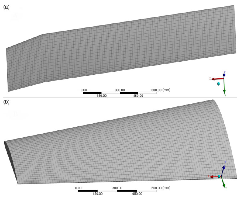
• Mesh generation by the ANSYS solver offers efficient and high-quality grid partitions for both wing shapes. Two meshing elements types were used in the FEM and TO methodologies. The meshing elements are high-quality hexahedral and tetrahedral. The total number of nodes and elements for the fixed segment were 54,185 and 10,152, respectively, while for the moving segment their total numbers were 25,077 and 4,704, respectively. Figure 4 shows the meshed models of the fixed and moving span morphing wing segments.
Figure 4. Meshing model of (a) moving and (b) fixed wing segment.
-
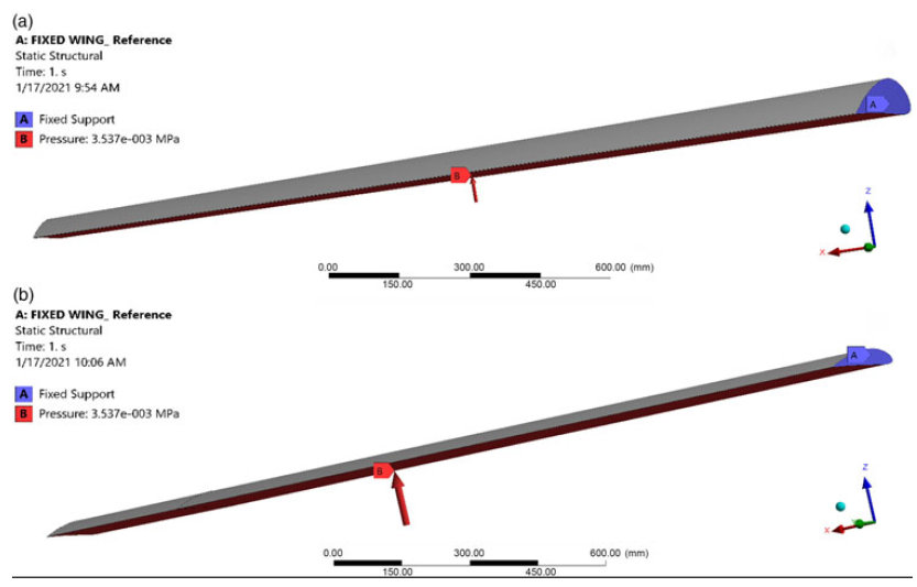
• The boundary conditions expressed by the desired mechanical behaviour and properties (material properties definition, analysis settings and loading conditions) were defined. The variable span morphing wing was mounted on the aircraft fuselage, with the moving segment sliding inside the fixed segment. The boundary conditions, fixed supports and the load applications for both wing segments are shown in Fig. 5. Static structural analysis was performed for the fixed and moving segments by enforcing identical boundary conditions. Therefore, in the static structural domain, a fixed support was inserted at the root chord for both segments. The load is distributed uniformly on all nodes situated on the bottom surfaces of the moving and fixed wing segments. This load is applied with the same values along the Y direction for both segments. To apply the load on the wing segments. The pressure calculated following the aerodynamic results was considered to apply the load on the wing segments, and the magnitude of the load was 3,537Pa(Reference Elelwi, Kuitche, Botez and Dao24,Reference Chethan, Zuber, Shenoy and Kini42) .
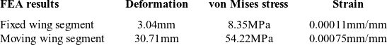
Table 6 Results for the three parameters (deformation, stress and strain) for fixed and moving segments at ultimate pressure
Figure 5. Boundary condition, fixed support and loading application for (a) fixed and (b) moving segments.
-
• Post-processing was applied after solving the equations of the structural calculations such as stress, deformation and strain to obtain the converged solution. The static analysis solver allows contour plots, vector plots, 2D and 3D surface schemes to be designed, and to visualise the finite element analysis results. It can also offer animation to display the results dynamically.
-
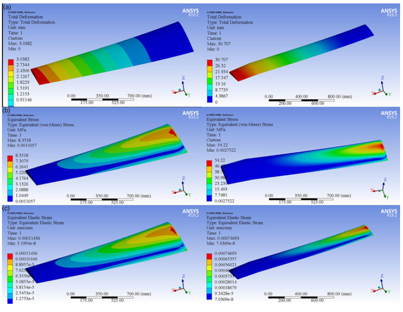
• The results are obtained by static structural analysis. Following the optimisation process, von Miss stresses, stresses and deformation values are obtained from the static structural analysis. The FEM results, expressed in terms of deformation, stress and strain, for the morphing wing segments respect the safety limits of the selected material’s mechanical properties. The FEA results obtained on the considered wing segments are described in Table 6 and further shown in Figs. 6(a), (b) and (c).
Figure 6. (A) Total deformation, (B) von Mises stress and (C) elastic strain for (a) fixed, and (b) moving segments of the variable-span morphing of a tapered wing aerofoil.

5.0 TOPOLOGY OPTIMISATION RESULTS FOR WING COMPONENT LOCATIONS
After finalising the FEA model analysis, linear static analysis was conducted. The obtained results were checked before setting up the optimisation process, as shown in Fig. 7. The material density was determined as a design variable to optimise the material density distribution from its continuous range(Reference Li, Zhao and Liu43). Two responses were considered for our design case: minimising the structural compliance and the volume fraction. The volume fraction is considered as a constraint. The optimisation results show that all elements are located in high-stress/deformation zones, and ensure that the elements inside these zones are essential for structural design. It can be observed that the elements outside such high-pressure areas can be removed(Reference Wang, Lu and Zhou12,Reference Li, Zhao and Liu43) .

Figure 7. TO results for (a) fixed and (b) moving segments of the variable-span morphing of a tapered wing.
The TO process shows how the objective function changes with the number of iterations. In this investigation, 41 and 49 iterations were required for the fixed and moving segments, respectively, until convergence was achieved, as shown in Fig. 8.

Figure 8. Convergence graph of TO for (a) fixed wing and (b) moving wing.
The iterative process modifies the strain energy, so as the strain energy decreases, the structural rigidity gradually increases.
The main objective of the analysis for TO for the variable span morphing wing is to define the wing components that must be redesigned efficiently. The most suitable locations of the components inside the wing with maximum efficiency will be found in the new optimised structure. The TO of the variable span morphing wing for the maximum speed case at the selected wing component locations is shown in Fig. 9. It can be seen from Fig. 9 that the analysis provides the approximate locations of the wing components, such as ribs and spars, required to support their loads correctly.

Figure 9. Wing component locations based on the TO results for (a) fixed and (b) moving segments.
6.0 REMODELLING WING DESIGN BASED ON TOPOLOGY OPTIMISATION
Based on the TO results shown in Fig. 9, the wing components are redesigned and analysed for both wing segments using the same selected material. The first investigation evaluated a potential lightweight structure for the first wing model, as described in Section 2.1. The basic wing model was composed of 100% solid aluminium 2024-T3, with masses of 112 and 45kg for the fixed and moving segment, respectively.
The ribs were first placed at the distances proposed by the TO method, at the locations indicated in Table 7.
Table 7 Proposed locations for wing ribs for fixed and moving segments

For this case study, the TO method suggested that the fixed segment must be designed with a two-spar configurations, as its ribs are housing the moving segment. Accordingly, the moving segment must be designed with a two-spar configurations to support the wing components, especially at full wing extension, as shown in Figs. 9 and 10.
The baseline TO results show that the high-strain area is located in the middle of the wing area. It can thus be concluded that it is necessary to support the high-strain area in both wing segments by strengthening the shear stress generated by the reactions to the aerodynamic loads under various flight conditions.
After remodelling the TO results for both wing segments, a parametric CAD model of the wing components (Fig. 10) was developed based on their density distribution (Fig. 9)(Reference Komarov, Kishov, Kurkin and Charkviani44).

Figure 10. Parametric CAD model of (a) fixed and (b) moving segments with their components based on TO.
Comparison of the weight of the initial structure of the solid wing segments with the weight of the optimised wing segments reveals that reductions of the total wing weight by 16.3kg for the fixed wing segment and 10.3kg for the moving wing segment were achieved.
6.1 FEM based on TO
The described approach based on the simulation-based TO method can provide a detailed structural design of the variable-span morphing wing. This offers a new way to reduce the aircraft’s structural weight. The redesign based on the TO method suggested a variable-span morphing wing model consisting of a thin skin, twin spars, seven ribs and multiple support elements, as shown in Figs. 9 and 10. The baseline design consists of the external surface skin to sustain the aerodynamic loads and distribute the aerodynamic loads to the internal components, such as spars, ribs and stringers. The main function of the two spars is to support the multiple loads acting on the wing, including the bending moment and shear force, as well as to support the wing structure against any torsion created by load lifting. The ribs are used to retain the geometrical shape of the wing section with the aim of distributing the external loads evenly on the wing skin and thereby prevent undesired wing deformation. The stringers are applied in the design to enhance the wing’s rigidity(Reference Zhang, Zhao and Si45).
To achieve a stiffened and reliable variable-span morphing wing, the main parameters of its fixed and moving wing segments components are defined as follows:
-
• A wing skin thickness of 2mm for both segments
-
• A spar thickness of 6mm for both segments
-
• A rib thickness of 6mm for both segments
-
• Flat stringers with thickness of 4mm for the fixed segments, and round stringers with diameter of 3mm and thickness of 1mm.
-
• A stringer thickness of 8mm for the moving segment.
Furthermore, as they are parallel, the distance between the two spars is defined as 351.56mm for the fixed segment and 163.38mm for the moving segment of the wing.
The objective for designing such a wing is to enhance the capabilities of the Unmanned Aerial Vehicle (UAV) to accomplish multiple missions during the same flight. This UAV is mainly used for surveillance and security purposes, as it can cover all its targets in one flight by reaching its intended destination rapidly while expanding the flight range without refuelling.
The variable-span morphing wing shapes for various wingspan extensions and different flight speeds were re-analysed using the CFD calculations. The static analysis parameters for the optimised wing were selected for four flight speeds at all three wingspan extensions to ensure compliance throughout each flight phase, as described in Table 8.
The same material properties were selected as explained in the previous analysis for the solid wing segments, as described in Table 4. Hexahedral meshing was performed using the MultiZone mesh method with the aim of obtaining highly accurate results. The mesh size was selected to be the same for both wing segments: 15mm for the wing skin, 6mm for wing spars and 3mm for the ribs and stringers. The total number of nodes was equal to 836,885, and the total number of elements was equal to 243,976 for the entire wing. Figure 11 shows the meshing of the wing structure and its components.
The same methodology as mentioned in Section 6 was used in this case study. The boundary conditions applied on the variable-span morphing wing were defined. The root chord of the variable-span morphing wing was fixed, and the load was applied for wingspan extensions of 50% and 75%, at a speed of 17m/s, and for the wingspan extension of 0% (original) and 25% at a speed of 51m/s, as shown in Fig. 12.
Table 8 FEA specifications for MVSTW at all span extensions and different flight speeds

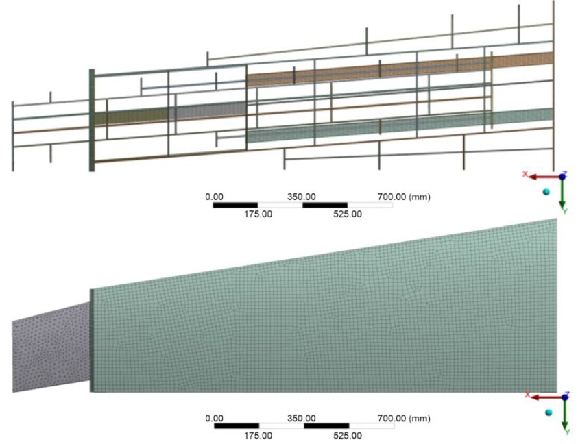
Figure 11. Grid meshing of the variable-span morphing tapered wing and its components.
Table 9 Results for the three characteristics (deformation, stress and strain) at selected wingspan extensions and flight speeds


Figure 12. Boundary conditions for variable morphing for wingspan extensions of (a) 50% and 75% at 17m/s and (b) 0% and 25% at 51m/s.
The given loads for the multiple wingspan extensions and speeds were applied along the Y direction for the variable-span morphing wing, with the pressures calculated according to the aerodynamic results described in Table 8.
6.2 Evaluations of the static structural analysis of the optimised MVSTW
Static analysis was performed to evaluate the optimised MVSTW. The loads were defined as per the lift forces that were obtained for the various wingspan extensions and flight speeds. The same boundary conditions were also considered in this investigation and the safety factor, as given in Table 8.
The results of the static structural analysis are expressed in terms of deformations, von Mises stresses and strains for eight selected cases (Table 9); the results are illustrated in Figs. 13, 14 and 15.

Figure 13. Total deformation of the MVSTW for (a) Wing extension of 50% and speed of 17m/s, (b) wing extension of 75% and speed of 17m/s, (c) wing extension of 50% and speed of 34m/s, (d) wing extension of 75% and speed of 34m/s, (e) wing extension of 0% and speed 51m/s, (f) wing extension of 25% and speed of 51m/s, (g) wing extension of 0% and speed of 68m/s and (h) wing extension of 25% and speed of 68m/s.
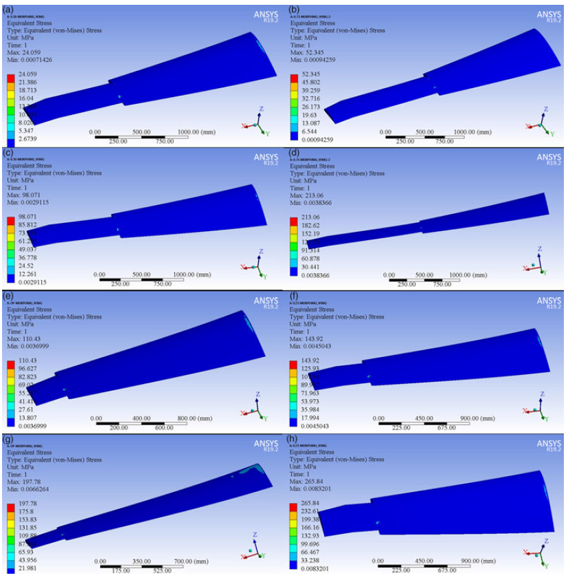
Figure 14. von Mises stress of the MVSTW for (a) wing extension of 50% and speed of 17m/s, (b) wing extension of 75% and speed of 17m/s, (c) wing extension of 50% and speed of 34m/s, (d) wing extension of 75% and speed of 34m/s, (e) wing extension of 0% and speed of 51m/s, (f) wing extension of 25% and speed of 51m/s, (g) wing extension of 0% and speed of 68m/s and (h) wing extension of 25% and speed of 68m/s.

Figure 15. Equivalent strain of the MVSTW for (a) wing extension of 50% and speed of 17m/s, (b) wing extension of 75% and speed of 17m/s, (c) wing extension of 50% and speed of 34m/s, (d) wing extension of 75% and speed of 34m/s, (e) wing extension of 0% and speed of 51m/s, (f) wing extension of 25% and speed of 51m/s, (g) wing extension of 0% and speed of 68m/s and (h) wing extension of 25% and speed of 68m/s.
The results obtained from the MVSTW simulations are depicted in Figs. 13, 14 and 15, and in Table 9. Note that the values of the mechanical properties, that is, the deformation, stress and strain, increased with increasing aerodynamic loads. Meanwhile, the aerodynamic loads increase with the wingspan extension (increasing the wing surface area) and also changes in the flight speed(Reference Ajaj, Friswell, Saavedra Flores, Keane, Isikveren, Allegri and Adhikari46). The mechanical properties increase dramatically at the large wingspan extensions of 50% and 75%, and at increased cruise and maximum flight speeds. Therefore, the wingspan extensions of 50% and 75% are suggested only for the minimum speed and loiter phases. The main benefit of symmetric wingspan extension is to increase the aerodynamic efficiency for maximised range flight, and to reduce the take-off and landing distances. The wingspan at the original position without extension (0%) and at 25% extension can be used to ensure high manoeuvrability, and to reduce the flight time, as the mechanical properties remain within the safe domain of the wing’s resistance to failure.
According to the FEA results, it is clear that the morphing of the structure of the designed wing is suitable for the rolling control strategy using the asymmetric span morphing technique. However, the optimum rolling mechanism should consider that both sides of the wing’s span must expand gradually and symmetrically. In addition, the wingspan should extend smoothly and effectively to avoid structural fatigue, since the results obtained for the changes of the deformation, stress, and strain show dramatic increases, being severely affected by the aerodynamic loads. An example of these increases is presented in Table 9 for a wingspan extended from its original position to 75% of its length.
The structural optimisation of the MVSTW under stiffness requirements is used to predict the perfect layouts of the wing components within the design space. The TO results suggest that the best possible weight values of the MVSTW for both segments are the following: the optimised weight of the fixed segment is 16.3kg, and the optimised weight of the moving segment is 10.3kg, compared with the calculated values of 112 and 45kg for both solid wing segments, respectively. The structural layouts based on the mechanical characteristics, such as stiffness and strength, involve two-spar and seven-rib configurations. Moreover, to achieve the multi-mission requirements, additional support parts, such as stringers and stiffeners, are added to overcome mechanical fatigue (Fig. 10) by enhancing the structural integrity and avoiding structural failure. The proposed arrangement and allocation of wing components was proved to attain the robustness and integrality required for the MVSTW, and to achieve important weight reductions through the topological optimisation(Reference Amendola, Dimino, Amoroso and Pecora47).
7.0 CONCLUSIONS AND FUTURE WORK
This paper addresses the current progress in the field of TO techniques applied in UAV design, and in new component allocation for the MVSTW. The optimisation was carried out using the ANSYS Mechanical tools, enabling the formulation and then solution of appropriate TO problems. The optimisation framework was developed for solid wing segments, with the aim of predicting the locations of the variable span morphing wing components within the design space.
The main objective of this optimisation was to define and understand the feasibility of internal wing components, such as ribs, spars and other structural components. This innovative approach was proposed for the telescopic mechanism of the MVSTW, which includes the sliding of the telescopically extended wing into the fixed wing segment. The study aimed to minimise the overall structural compliance, and maximise its stiffness to enhance the structural performance and meet the structural integrity requirements of the MVSTW. The TO results suggested that the fixed and moving wing segments must be designed with two-spar configurations, and seven ribs with their support parts. The solid wing weight for both segments was reduced significantly from 112 to 16.3kg for the fixed wing segment, and from 45 to 10.3kg for the moving segment for the optimised MVSTW. The wing structural components, such as ribs, spars and support elements, were designed and further developed based on the TO results for both MVSTW segments. Sequential FEAs were performed on the assembled variable-span morphing wing at various wingspan extensions and four different flight speeds. This study is a follow-up of the previous aerodynamic optimisation study, in which the aerodynamic loads associated with wingspan lengths and speeds were obtained for multiple flight conditions.
The FEA results for the topology-optimised MVSTW at different wingspan extensions and flight speeds highlight the important benefits of using TO. The results also show that the optimised MVSTW configuration can achieve multiple-mission flight. The optimised wing shape satisfies the structural integrity’s design criteria because the wing components’ allocation was based on the TO approach.
Future research will include optimisation of the novel MVSTW obtained in this investigation. Numerical TO techniques will be applied to the wing components to enhance the wing stiffness while providing weight savings for better performance. The TO approach will be performed for each wing component individually. This optimised wing will be used as a baseline reference for the subsequent optimisation process to produce a lightweight wing while maintaining its structural stiffness and robustness. The weight of the optimised wing could thereby be reduced by 30–50% from the initial value. Additional investigation phases will be carried out to obtain a robust and reliable adaptive morphing wing. The TO will be performed using composite material to obtain a greater weight reduction for the MVSTW. The MVSTW structure and actuation mechanism integration will be investigated after carrying out the TO of the wing using composite materials.
Acknowledgements
Special thanks are due to the Natural Sciences and Engineering Research Council of Canada (NSERC) for the Canada Research Chair Tier 1 in Aircraft Modelling and Simulation Technologies funding. We would also like to thank Mrs. Odette Lacasse and Mr. Oscar Carranza for their support at the ETS, as well as to Hydra Technologies’ team members Mr. Carlos Ruiz, Mr. Eduardo Yakin and Mr. Alvaro Gutierrez Prado in Mexico for their collaboration.