1.0 INTRODUCTION
Aircraft development and certification is a lengthy and costly process. Furthermore, the market is constantly changing with new demands such as more passengers, greater cruise range, new engines, new technology, and new environmental considerations. Aircraft typically have many derivatives to satisfy these new demands(Reference Robinson and Melary1). Derivative designs are advantageous to manufacturers and airlines. Aircraft parts are shared between the baseline aircraft and its derivatives, reducing the manufacturing cost and simplifying the maintenance process. Training time and cost for pilot and maintenance crew are also reduced relative to brand-new aircraft designs. As a consequence, many researchers have studied aircraft derivative and aircraft family design methods(Reference Hibma and Wegner2–Reference Moon, Park and Simpson17). Richard et al, Reinhold, Robert et al, and Deepak et al utilized market requirement analysis to identify the important criteria for derivative design and considered altering constraints for the design problem(Reference Hibma and Wegner2–Reference Kumar, Chen and Simpson6). Jonathan et al identified the candidate product family members from the generation of a Pareto frontier(Reference Yearsley and Mattson7,Reference Yearsley and Mattson8) . Timothy et al employed a Multi-Objective Genetic Algorithm (MOGA) for derivative design. The product baseline and its family were simultaneously optimised using a genetic algorithm while considering different platform levels(Reference Simpson and D'Souza9–Reference Khajavirad, Michalek and Simpson11). Furthermore, James et al and Dongwook et al proposed an evolutionary method and data mining technique to design a family of aircraft(Reference Lim and Mavris12–Reference Freeman, Lim, Garcia and Mavris14). Prasetyo considered the aerodynamics discipline for family design of transport aircraft(Reference Edi15), and David et al implemented a library of interchangeable components for Unmanned Aerial Vehicle (UAV) family design(Reference Pate, Patterson and German16). A Multi-Objective Particle Swarm Optimisation (MOPSO) approach was suggested by Seng Ki et al(Reference Moon, Park and Simpson17). These approaches designed the baseline aircraft and its derivatives simultaneously using a complete set of design variables. Moreover, these researchers assumed a set of requirements for derivative conceptual design. However, these requirements often differ from actual market requirements that may have been unforeseen during the development of the baseline aircraft due to new emerging requirements. Therefore, a more effective design process for aircraft derivative design is required to properly consider changing market demands and the emergence of new requirements. This process facilitates the design of aircraft derivatives when the market demands new capabilities that may not have been foreseen when the baseline aircraft was designed. In this research, a derivative design method is proposed that considers new market requirements for existing aircraft. These new market requirements were analyzed to identify important features for derivative design.
The proposed design process considered uncertainty in the design optimisation process. In recent years, uncertainty has been considered in design optimisation to ensure a conservative optimum design. The Reliability-Based Design Optimisation (RBDO) and Possibility-Based Design Optimisation (PBDO) methods were developed to consider the influence of uncertain variables and parameters on design optimisation(Reference Youn, Choi and Du18,Reference Agarwal19) . The RBDO method is applied to consider uncertainty when information from the uncertain parameters is sufficient to generate accurate input for statistical distribution functions(Reference Youn, Choi and Du18,Reference Agarwal19) . When sufficient amounts of uncertain data are not available, the probabilistic method cannot be used for reliability analysis and design optimisation. For such cases, the PBDO method can be used for considering uncertainty in design optimisation(Reference Du, Choi, Youn and Gorsich20). The PBDO uses a fuzzy function for modeling uncertain parameters and is useful for cases that have insufficient data to produce the probability density functions(Reference Youn, Choi and Du18,Reference Du, Choi, Youn and Gorsich20) . In this research, the PBDO method was applied for handling uncertain parameters, since sufficient data concerning these parameters was not available for calculating probability density functions and are better handled by engineering judgment and the examination of available data.
A derivative of the Found Aircraft Expedition 350 was considered as the application in this paper(21). Found Aircraft is a light aircraft manufacturer in Ontario, Canada. The Found Aircraft Expedition 350 was developed from the baseline FBA-2 aircraft and was designed for flight training and private use. The baseline aircraft was developed in 1961 to withstand and thrive in the harsh conditions of North America's undeveloped northern land with equipment including tundra tires, floats, and skis(21). A change from the normally aspirated engine type to a turbocharged engine was considered in order to satisfy new demands from dealers. A derivative design optimisation technique was performed to enhance the stability characteristics with the new engine. The predicted results of the performance analysis module were compared with actual flight data for certification to evaluate the analysis module. In addition, the PBDO method was implemented to consider uncertainty. The flight operation conditions were considered as uncertain parameters in order to avoid repetitive computation for all performance and stability constraints for every environmental condition. The PBDO method will make sure that each constraint was evaluated at the worst possible value of air density. This ensures that each constraint will be evaluated in a conservative way(Reference Neufeld, Nhu-Van, Lee and Kim22). A set of aircraft analysis tools including aerodynamics, performance, stability, weight estimate, engine, and propeller analysis were implemented in an optimisation framework. The results were compared with known aircraft performance data.
2.0 DESIGN OPTIMISATION UNDER UNCERTAINTY
2.1 Uncertainty
Uncertainty is inherent in all types of simulation-based design. When the optimisation is performed without considering the uncertainty, certain active constraints in the deterministic optimisation result may cause system failure. Reliable solutions lie farther inside the feasible design region than the deterministic optimisation result while satisfying the targeted reliability level. In this research, the flight condition was considered as an uncertain parameter since it changes during flight phases. The range of the overall flight phase was selected as a boundary for the uncertain parameter. The PBDO method satisfies target possibility on the selected range of flight environments. This work reduces the computation time for different evaluating different flight phases.
2.2 Possibility-based design optimisation (PBDO)
The PBDO method was developed to address uncertainty in design variables and parameters for which insufficient data is available to calculate a probability density function(Reference Choi and Youn23–Reference Choi, Du and Youn26). This is desirable since a conservative optimum design is preferred when accurate statistical information is not available. The possibility-based method treats input variables as fuzzy variables. Fuzzy variables with membership functions are implemented for the possibility method instead of the Probability Density Function (PDF) of random variables. There are two advantages of the fuzzy analysis compared to the probability analysis. First, the fuzzy input variables can be defined more easily than the input random variables when there is not enough statistical data available. Secondly, extended fuzzy operations are much simpler than probability-based methods, especially when a large number of variables is not available(Reference Zhao and Xue27). The possibility measure Π should comply with the following axioms(Reference Zhao and Xue27):
Boundary requirement: Π(∅)=0, Π(Ω)=1,
Monotonicity: if A1⊆A2, then Π(A1)≤ Π(A2),
Union measure: Π(∪i∈ I Ai) = max i∈ I{Π(Ai)},
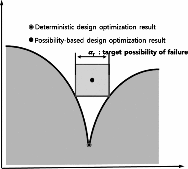
where ∅ is the empty event and Ω is the fuzzy event of whole space. {Ai, i∈ I} is a partition of universal event Ω. The general concept and formulation of the PBDO are shown in Fig. 1 and Equation (1)(Reference Savoia24).
 $$\begin{equation}
\begin{array}{l} {\rm{minimize}}\;{\rm{Cost}}\left( d \right)\\ {\rm{subject}}\;{\rm{to}}\;{\rm{\Pi }}({G_i}(X)) > 0 \le {\alpha _t},\;i = 1,\;2, \cdots ,np\\ \quad \quad \quad \quad {d^L}\ \le \ d\ \le \ {d^U}\end{array}
\end{equation}$$
$$\begin{equation}
\begin{array}{l} {\rm{minimize}}\;{\rm{Cost}}\left( d \right)\\ {\rm{subject}}\;{\rm{to}}\;{\rm{\Pi }}({G_i}(X)) > 0 \le {\alpha _t},\;i = 1,\;2, \cdots ,np\\ \quad \quad \quad \quad {d^L}\ \le \ d\ \le \ {d^U}\end{array}
\end{equation}$$d is the design variable vector, Gi(X) is the ith constraint function,X is the fuzzy variable vector, П (•) is the possibility measure, and αt is the target possibility of failure.

Figure 1. The optimum result of PBDO.
In this paper, it was assumed that the non-interactive fuzzy variables Xi had its membership function Πxi(xi) satisfying properties: unity, strong convexity, and boundedness(Reference Youn, Choi and Park25,Reference Zadeh28) . These three properties make it possible for non-interactive input fuzzy variables Xi, i=1, . . ., nf to be uniquely transformed to fuzzy variables Vi with non-interactive isosceles triangular membership functions as
 $$\begin{eqnarray}
\begin{array}{l}
{\Pi _{{V_i}}}\left( {{V_i}} \right) = \left\{\begin{array}{*{20}{c}}
{{v_i} + 1,\ - \quad 1 \le {v_i} \le 0}\\ {1 - {v_i},\quad 0 \le {v_i} \le 1}\end{array} = 1 - \left| {{v_i}} \right| \right.\\[6pt]
\quad \left| {{v_i}} \right| \le 1,{\rm{\ \ \ }}i = 1, \ldots ,nf\end{array}
\end{eqnarray}$$
$$\begin{eqnarray}
\begin{array}{l}
{\Pi _{{V_i}}}\left( {{V_i}} \right) = \left\{\begin{array}{*{20}{c}}
{{v_i} + 1,\ - \quad 1 \le {v_i} \le 0}\\ {1 - {v_i},\quad 0 \le {v_i} \le 1}\end{array} = 1 - \left| {{v_i}} \right| \right.\\[6pt]
\quad \left| {{v_i}} \right| \le 1,{\rm{\ \ \ }}i = 1, \ldots ,nf\end{array}
\end{eqnarray}$$The transformation can be written as:
ΠXi, L(Xi) and ΠXi, R(Xi) are the left side and the right side of the input fuzzy variable membership function Xi, respectively. In addition, di is the maximal grade of this membership function.
3.0 BASELINE AIRCRAFT
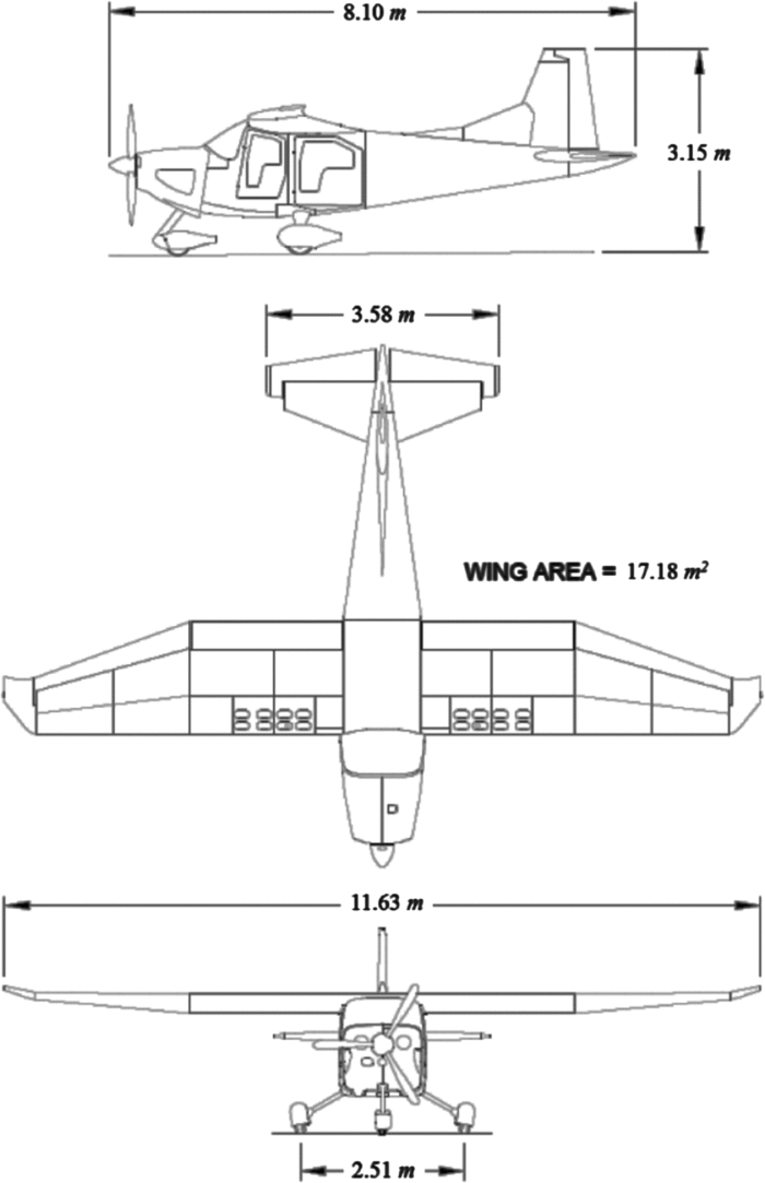
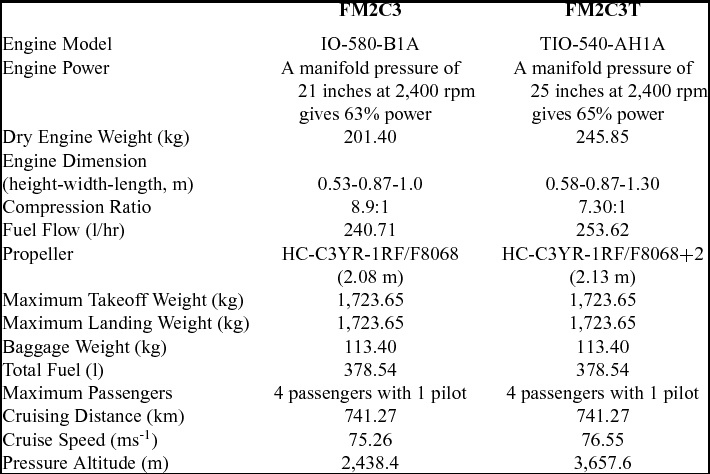
The Expedition FM2C3 is powered by Lycoming IO-580-B1A engine and was FAA certified in 2008. The wing, rear fuselage, engine mount, and landing gear are all attached to a steel frame. The other major structural elements and flight surfaces are made of aluminum. Found Aircraft developed the FM2C3T that uses the Lycoming TIO-540-AH1A turbocharged engine. They upgraded the FM2C3 with a turbocharged engine to satisfy new requirements including high-altitude operation in Alaska and other mountainous regions. The FM2C3 and FM2C3T have the same geometry shown in Fig. 2. Table 1 shows the specification of the Expedition 350 aircraft.

Figure 2. Three view of expedition 350(21).
Table 1 Specification of expedition 350(21)

A reduced set of certification requirements were considered for the Supplemental Type Certification (STC) due to the similarity in configuration between the FM2C3T leading to reduced flight test matrix(29). The FM2C3 and FM2C3T have the same wing geometry, so stalling speed was not affected by the engine change. Stalling speed is defined “for reciprocating engine-powered aircraft with the engine idling, the throttle closed or at not more than the power necessary for zero thrust”(29). TIO-540, the turbocharged engine used by the FM2C3T, produces 231.62 KW up to an altitude of 1,524 m. This is the same as the sea-level output of the IO-580 that the FM2C3 uses. Therefore, the takeoff and climb performance at sea level are same as the baseline aircraft. Furthermore, the turbocharged engine has no effect on the landing distance. The landing data from the FM2C3 flight manual was acceptable. TIO-540 produces 220.59 KW up to 3,657.6 m. Therefore, the FM2C3T outperforms the baseline aircraft at higher altitudes. This means that additional flight tests at high altitudes are required to meet the requirements for obtaining an STC.
4.0 AIRCRAFT DERIVATIVE DESIGN
In this research, performance and stability analysis modules were implemented for an optimisation problem to enhance performance and stability characteristics to new requirements. Engine, propeller, and weight estimate modules were implemented as sub-routines of the performance and stability analysis modules.
4.1 Requirement change and additional considerations
In response to dealer requests, a program to develop a derivative aircraft that asked the new aircraft can operate in high altitude conditions was begun. High-altitude conditions have low air density, which reduces the amount of lift generation over a wing at any given true airspeed. The low air density reduces the performance of aircraft engines as well. Aircraft operating at high-altitude airfields require more takeoff length and have reduced rate of climb. To overcome the negative effects of the reduced air density, various methods were proposed. First, aircraft weight can be reduced with a smaller number of passengers or lower payload size. The second consideration is increasing engine power. A more powerful engine can enhance the aircraft acceleration and reduces takeoff length. However, the additional weight of the engine and fuel can mean more cost and have a negative effect on other aspects of aircraft performance. Third, wing size can be increased for high-altitude conditions, but this increases wing weight, drag, and fuel consumption during cruise. Lastly, additional high-lift devices to the wing can be implemented. However, these devices increase weight and mechanical complexity, which increases manufacturing and maintenance costs as well.
Found Aircraft implemented a turbocharged engine that has more power than normal aspirated engine to satisfy new requirements without configuration changes. In this paper, a turbocharged engine from the FM2C3T was considered along with changes to the main wing and the empennage geometry and location.
4.2 Performance analysis module
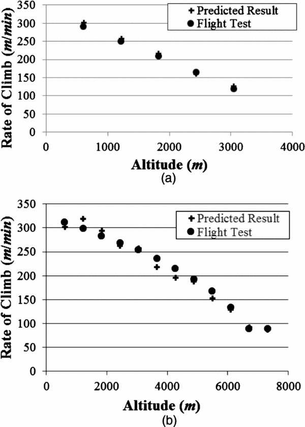
The performance analysis module was developed by using simplified performance equations from references(Reference Anderson30–Reference Nelson31). It determines performance criteria such as drag, turn radius, power, air density, fuel flow, climb angle, RPM, load factor, density altitude, lift, L/D, equivalent airspeed, thrust, velocity, power setting, climb rate, propeller efficiency, bank angle, and turn rate(Reference Anderson30). Turn, maximum climb rate, minimum glide angle, minimum sink rate, maximum velocity, and minimum fuel were predicted for each flight phase. Figure 3 shows a comparison of climb rate between actual flight data and predicted results from the analysis module. Figure 3(b) contains higher-altitude data than Fig. 3(a) since the FM2C3T with a turbocharged engine is capable of flight at higher altitudes.

Figure 3. Comparison of actual flight data and analysis result. (a) Comparison of FM2C3 data and analysis result. (b) Comparison of FM2C3T data and analysis result.
Rate of climb is a good criterion to show the performance difference between two aircraft with different engines and is derived from Equation (4)(Reference Anderson30,Reference Nelson31) .
 $$\begin{equation}
R/C = V\left[ {\frac{T}{W} - \frac{1}{2}\rho {V^2}{{\left( {\frac{W}{S}} \right)}^{ - 1}}{C_{D.0}} - \frac{W}{S}\frac{{2K}}{{\rho {V^2}}}} \right]
\end{equation}$$
$$\begin{equation}
R/C = V\left[ {\frac{T}{W} - \frac{1}{2}\rho {V^2}{{\left( {\frac{W}{S}} \right)}^{ - 1}}{C_{D.0}} - \frac{W}{S}\frac{{2K}}{{\rho {V^2}}}} \right]
\end{equation}$$T is the thrust, V is the velocity, and ρ is the air density. CD.0 is the drag coefficient, S is the wing reference area, W is the mass of aircraft, and K is the drag-due-to-lift factor.
The performance analysis module was found to predict actual performance to within a small error for both aircraft. The performance criteria were implemented as constraints of the derivative design to determine performance characteristics as the aircraft geometry is changed during the optimisation process. The performance of the derivative aircraft is maximized while satisfying stability requirements.
4.3 Stability analysis module
The stability analysis module calculates stability criteria such as the static margin, dihedral effect, yaw stiffness, frequency and damping ratio of short period, and frequency and damping ratio of Dutch roll. Equations (Reference Brown and Swihart5) through (Reference Khajavirad, Michalek and Simpson11) define this criteria respectively(Reference Nelson31).
SM is the static margin, xn is the neutral point, ![]() $\bar x$ is the location of the aircraft's Centre of gravity, and
$\bar x$ is the location of the aircraft's Centre of gravity, and ![]() $\bar c$ is the wing mean aerodynamic chord.
$\bar c$ is the wing mean aerodynamic chord.
Clβ is the dihedral effect, λ is the taper ratio, AR is the aspect ratio, and Г is the wing dihedral angle.
Cnβ is the yaw stiffness, Cnβwf is the yawing moment derivative for the vertical stabilizer related to side-slip angle β. ηc is the efficiency factor of the vertical tail, Vυ is the vertical tail volume ratio, and CLαυ is the lift curve slope for vertical tail. dσ/dβ is the change in side-wash angle with a change in side-slip angle.
 $$\begin{equation}
{\omega _s} = \sqrt {\frac{{{Z_\alpha}{M_q}}}{{{u_0}}} - {M_\alpha }}
\end{equation}$$
$$\begin{equation}
{\omega _s} = \sqrt {\frac{{{Z_\alpha}{M_q}}}{{{u_0}}} - {M_\alpha }}
\end{equation}$$ωs is the short period frequency, Mq and Mα are the differentials of pitching moment for pitch rate q and angle-of-attack α respectively. Zα is the aerodynamic force with respect to angle-of-attack and u0 is the forward velocity.
 $$\begin{equation}
{\zeta _s} = - \frac{{{M_q} + {M_\alpha } + \frac{{{Z_\alpha }}}{{{u_0}}}}}{{2{\omega _s}}}
\end{equation}$$
 $$\begin{equation}
{\omega _D} = \sqrt {\frac{{ - {Z_u}g}}{{{u_0}}}}
\end{equation}$$
$$\begin{equation}
{\omega _D} = \sqrt {\frac{{ - {Z_u}g}}{{{u_0}}}}
\end{equation}$$ζs is the short period damping ratio, ωD is the Dutch roll frequency, Zu is the change in z-force with respect to speed, and g is the acceleration of gravity.
 $$\begin{equation}
{\zeta _D} = \frac{{ - \frac{{\partial X}}{{\partial u/m}}}}{{2{\omega _D}}}
\end{equation}$$
$$\begin{equation}
{\zeta _D} = \frac{{ - \frac{{\partial X}}{{\partial u/m}}}}{{2{\omega _D}}}
\end{equation}$$where ζD is the Dutch roll damping ratio, ∂X/∂u is the stability derivatives evaluated at reference flight condition, and m is the mass of the aircraft.
These were used as constraints and the objective for optimisation. When the engine was changed, the aircraft Centre of Gravity (CG) moved and the characteristics of stability changed. For this reason, the geometry and position of the main wing and empennage should be considered to maintain the stability characteristics. Table 2 shows comparison of stability characteristics of these aircraft from the stability analysis module.
Table 2 Stability analysis result

4.4 Uncertain parameters
Uncertainty is characterised as the incompleteness of knowledge due to deficiencies in information from the engineering analysis and design. Material properties, costs, operational environment, and human factors can be defined as uncertainty in design. Uncertainty can cause losses and violate constraints in the optimised design results. Understanding and identifying uncertainty are crucial to the designer since the type of uncertainty applicable to a given problem plays a key role in the quantification of its effect. Various sources of uncertainty exist and understanding them can provide guidance on how to reduce uncertainty in the prediction results(Reference Jaeger, Gogu, Segonds and Bes32–Reference Park, Chung, Behdinan and Lee34).
In this research, an uncertain parameter was introduced to cover different characteristics with respect to the altitude changes. The altitude was allowed to vary between sea level and 7,000m. A fuzzy membership function was defined to cover the interval of this altitude range. This enables the consideration of the whole range of operation and the results can satisfy constraints during the mission regardless of changes to the flight environment. D. Neufeld et al implemented an uncertain parameter to consider various operating environments during aircraft flight(21).
4.5 Derivative design optimisation
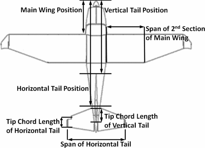
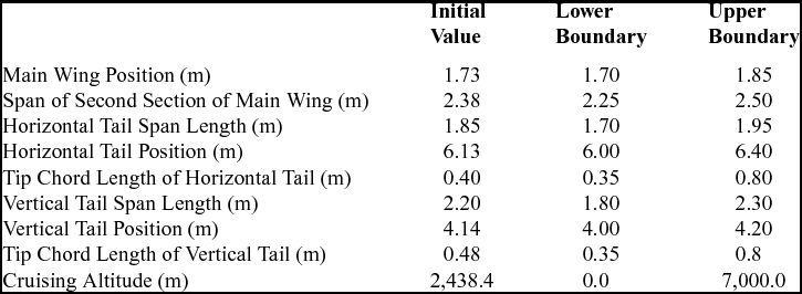
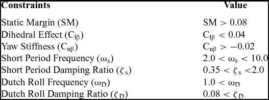
The stability and performance disciplines were implemented in this research. The objective of derivative design was obtaining better stability characteristics than the FM2C3T while satisfying given performance requirements. The geometry of the fuselage was not considered as a design variable. Cruising altitude was defined as an uncertain parameter, and the PBDO method was implemented to consider this uncertainty. Figure 4 shows the design variables from aircraft geometry, but the vertical tail span is not shown in the top view of the aircraft. Table 3 shows initial values and boundaries of these design variables and the uncertain parameter. The boundaries of design variables considered fuselage geometry and hanger size. Table 4 shows the stability constraints of the optimisation problem(35). Military specifications (MIL-F-8785C) define the requirements for the flying and handling qualities for various types of aircraft. In this research, the requirements for small aircraft were implemented as shown in Table 4.

Figure 4. Design variables on aircraft geometry.
Table 3 Design variables

Table 4 Constraints of aircraft derivative design(35)

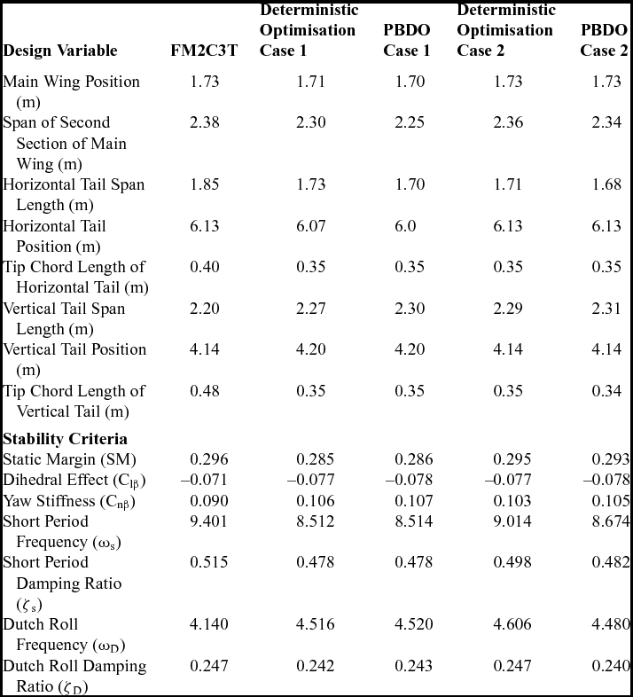
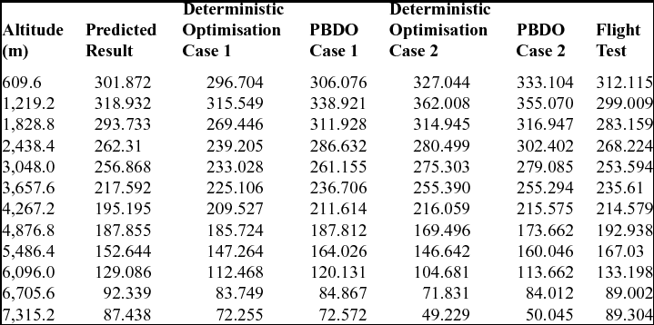
Table 5 shows the deterministic design optimisation and PBDO results and stability criteria values of the FM2C3T analysis data using the analysis tools. Two cases of optimisation were examined. The first case used all the design variables described above. The other case fixed the position of the main wing and empennage to save manufacturing costs. Table 6 shows the rate of climb from the optimisation results with actual flight test data. The deterministic design optimisation cases have a higher climb rate than the PBDO cases at between 3,600 and 4,300m, but lower climb rates at other altitudes. The PBDO results for case 1 and case 2 show better performance in both the predicted result and the actual flight test below 3,600m. Case 2 shows better climb rates at lower altitudes, but case 1 shows better performance at higher altitudes.
Table 5 Optimisation result and stability criteria

Table 6 Comparison of climb rate (m/min)

5.0 CONCLUSION
This research proposed an optimisation process for carrying out the conceptual design of an aircraft derivative in response to changing market requirements. Found Aircraft manufactured a new aircraft derivative named the FM2C3T that has a turbocharged engine to satisfy new demands from dealers, who requested a model with improved high altitude performance. The FM2C3 has a normally aspirated engine and could not satisfy the new requirements. In this paper, the new requirements were considered and a variant of the FM2C3 having a turbocharged engine was studied. An optimisation problem was formulated to enhance the stability and performance characteristics of Found Aircraft FM2C3 series of aircraft with the turbocharged engine. The main advantage of this research is the comparison of analysis tool with actual flight data. The actual aircraft performance data for certification were compared with predicted results to evaluate the performance analysis module and design result. The performance analysis module showed little error when compared with real flight data from the targeted aircraft. The location, span length, and tip chord length of the empennage and main wing were considered as design variables for derivative design. Additionally, the cruising altitude was considered as an uncertain parameter. The PBDO method was implemented to consider uncertainty in operating altitude to avoid violation of constraints from different atmospheric conditions from each flight phase. Two cases of derivative design were performed with a different number of design variables. The first case considered the whole set of design variables as described above. The other case excluded three design variables such as the position of the wing and empennage to reduce the development and manufacturing cost of the derivative aircraft. Both optimised designs show better stability characteristics and performance as rate of climb at a cruising altitude of 3,600m. The proposed process is applicable to other types of engineering products and may save considerable time and effort with derivative designs. Additionally, further considerations relevant to the certification process will be considered in this process to reduce the time and cost for STC.
ACKNOWLEDGEMENTS
This research is supported by an NSERC (National Sciences and Engineering Research Council of Canada) grant RGPIN227747-2012, and the authors gratefully acknowledge the valuable comments and help from David Min of Found Aircraft.


