


NOMENCLATURE
- AoA
-
Angle-of-Attack
- AVT
-
Applied Vehicle Technology
- BWB
-
Blended Wing Body
- CAAC
-
Civil Aviation Administration of China
- DARPA
-
Defense Advanced Research Projects Agency (USA)
- DLR
-
Deutsches Zentrum für Luft-und Raumfahrt (Germany)
- FAA
-
Federal Aviation Administration (USA)
- FEA/M
-
Finite Element Analysis/Method
- HALE
-
High-Altitude Long-Endurance
- IR
-
Infrared
- ISR
-
Intelligence Surveillance and Reconnaissance
- J-UCAS
-
Joint Unmanned Combat Air System
- LIDAR
-
Light Detection And Ranging
- LSP
-
Lightning Strike Protection
- LtCdr
-
lieutenant commander
- MALE
-
Medium-Altitude Long-Endurance
- MDAO
-
Multi-disciplinary Design Analysis and Optimisation
- MDO
-
Multi-disciplinary Design Optimisation
- NASA
-
National Aeronautics and Space Administration (USA)
- NATO
-
North Atlantic Treaty Organisation
- RAM
-
Radar Absorbent Material
- RAP
-
Radar Absorbent Paint
- RAS
-
Radar Absorbent Structures
- RCS
-
Radar Cross Section
- R&D
-
Research and Development
- SAA
-
Sense And Avoid
- STANAG
-
NATO Standardization Agreement
- TCAS
-
Traffic Collision Avoidance System
- UAV
-
Unmanned Aerial Vehicle
- UCAS-D
-
Unmanned Combat Air System – Demonstrator
- UCAV
-
Unmanned Combat Aerial Vehicle
- UCLASS
-
Unmanned Carrier-Launched Airborne Surveillance and Strike
- VLM
-
vortex lattice method
- WWI
-
First World War
- WWII
-
Second World War
1.0 INTRODUCTION
Before arming MQ-1 Predator UAVs with Hellfire laser-guided missiles in 2001, UAVs were mainly used for Intelligence, Surveillance and Reconnaissance (ISR) missions operating at high altitudes and low speeds in, mainly, permissive environments. Even so, unmanned aircraft were significantly more vulnerable to enemy defences, mechanical failures, and adverse weather conditions than their manned counterparts, virtually eliminating every cost and operational advantage related to unmanned operations(Reference Haulman1). Unmanned Combat Aerial Vehicle (UCAV) development plans have emerged as a configuration that integrates advanced technologies with increased survivability and tactical operational capabilities in dynamic and highly contested environments, while exploiting the reduced life cycle, acquisition and operating costs(Reference Wyatt and Hirschberg2).
This paper is organised in the following manner: Section 2 provides a brief historical background of Unmanned Aerial Vehicles (UAVs) in military operations. The main Advanced Technology Demonstrator programmes currently under development are identified in Section 3. Section 4 explains the main technological challenges for UCAV designs, the dominating design constraints and their impact on other aspects of the configuration. Section 5 briefly comments on the main airworthiness, airspace integration and navigation issues. Finally, Section 6 mentions the most relevant ethical concerns behind UAV/UCAV operations.
2.0 HISTORICAL BACKGROUND
The potential of unmanned aircraft in military operations was identified before WWI, with projects like Sperry's Aerial Torpedo and the Kettering Bug being developed as early as 1913. Similarly, during WWII, the TDR-1 assault drone was developed by the US Navy and successfully used against strategic Japanese facilities in 1944. With the end of WWII and the beginning of the Cold War, American defence authorities recognized that the need to obtain reliable intelligence without the risk associated to human aircraft operators was of extreme importance. Several secret organisations within the American government such as the National Reconnaissance Office, engaged in the development of ‘black’ projects from which multiple reconnaissance UAVs such as the Lightning Bug resulted, serving vital roles in ISR, and electronic and psychological warfare over territories like China, North Korea and Vietnam as early as 1962(Reference Ehrhard3). The most noticeable examples of secretive high-performance aircraft are the SR-71 Blackbird and the D-21 supersonic reconnaissance drone; both configurations operated at speeds over Mach 3 and altitudes ranging from 80,000 to 90,000 feet(Reference Merlin4). Similarly, during the 1970s and 1980s, agencies such as the Defense Advanced Research Projects Agency (DARPA), in conjunction with the private sector and international partners, developed medium-/high-altitude-long-endurance (M/HALE) platforms to replace manned reconnaissance aircraft like the U-2. These efforts resulted in modern UAVs such as Predator and Global Hawk(Reference Hirschberg5).
Subsequent armed conflicts proved the value of using UAVs in intelligence roles; US Navy LtCdr. Dixon concludes on UAV employment over Kosovo: ‘The primary military role of UAVs is real time data. . . (real time surveillance video) may significantly help the operational commander.’ and to ‘Aggressively continue UAV research and development’(Reference Dixon6, pp.12, 14).
Partially based on this success, the US Office of Naval Research Strike Technology Division conceived an ambitious and futuristic vision for fully autonomous aerial vehicles in the battlespace, from low-speed high-altitude surveillance platforms to high-performance strike and air combat aircraft; these requirements were considered unrealistic but ‘a worthwhile challenge and a useful direction in which to point R&D efforts’(7, p.8).
UAVs transitioned from surveillance to attack roles in 2001, when a MQ-1 Predator UAV, and later its larger variant the MQ-9 Reaper, armed with Hellfire laser-guided missiles fired against targets over Afghanistan and Kuwait(Reference Newcome8). The number of ‘drone strikes’ has continued to increase ever since; the Bureau of Investigative Journalism reports more than 400 US Predator/Reaper strikes over Pakistan from June 2004 to September 2015(Reference Serle and Fielding-Smith9). Today, it is estimated that more than 70 countries possess UAVs for civil and military applications, while more than 50 countries are currently designing and developing all types of UAVs(Reference Davis, McNerney, Chow, Hamilton, Harting and Byman10), with an expected increase in global expenses for research, development, testing and evaluation from $6.6B in 2013 to $11.4 Bn in 2022(Reference Harrison11).
3.0 ADVANCED TECHNOLOGY DEMONSTRATOR PROGRAMMES
By eliminating the immediate risk to human operators, UAVs are well suited for ‘dull, dirty, dangerous and deep’ missions; combined with advanced technologies, future UCAV platforms will be able to operate in highly contested airspace in pre-emptive and reactive roles such as suppression and destruction of enemy air defences, penetrating surveillance, and strike of high-value targets(12). These ‘first day operations’ require stealthy and agile configurations, which naturally take the form of highly blended flying-wing type designs. Therefore, this paper will deal with high-speed, high-performance, stealthy vehicles, while MALE/HALE configurations, even as they continue to be used as weapon-delivery systems today and in foreseeable future conflicts, are out of the scope of the paper.
3.1 US Navy UCLASS
In 1999, the US Department of Defense began investigating a new type of unmanned vehicle that could operate in combat missions while maintaining the low-cost benefits of UAVs. Initial research was undertaken by the US Air Force, DARPA, and Boeing with the X-45A UCAV demonstrator programme. It integrated several incremental development spirals culminating in the larger and more capable X-45C, with estimated deliveries by 2011(13). Shortly after, the US Navy and Northrop Grumman began developing a sea-based UCAV demonstrator designated X-47A.
In 2002, the US Air Force significantly expanded the operational requirements of the UCAV programme and reduced delivery times by 2 years, which resulted in excessive risk and cost increases. The US General Accounting Office, as well as the Department of Defense, recommended uniting efforts into a joint programme (J-UCAS) in 2003, which was later terminated in 2006 due to budget cuts and managerial divergences. However, in 2007, the J-UCAS programme was revived under the vague ‘Next Generation – Long-Range Strike’ project and the US Navy selected Northrop Grumman's X-47B ‘cranked kite’ design to be its proof of concept(Reference Whittenbury14) (Fig. 1). The programme was subsequently labelled as UCAS-D for Unmanned Combat Air System–Demonstrator(Reference De Neve and Wasinski15) and its first flight took place in February 2011(Reference Wise16). Despite on-going managerial divergences and changes in the programme's requirements(Reference Malenic17), the development of the X-47B continued, and major goals such as catapult-assisted take-off, arrested recovery and autonomous aerial refuelling were demonstrated(Reference Malenic18). In 2014, the Navy released a request for proposal for the new Unmanned Carrier-Launched Airborne Surveillance and Strike (UCLASS) aircraft, with emphasis on affordability, endurance, and timely fielding, while operations in highly contested airspace were not emphasized(Reference Gertler19). More recently, the UCLASS project has been replaced by an unmanned tanker request for proposal, MQ-25 Stingray, designed to deliver robust refuelling capabilities for other combat strike fighters(Reference Carey20,21) .

Figure 1. X-47B in flight.
On the other hand, Boeing continued with the development of their X-45C UCAV demonstrator, later named Phantom Ray, through self-funding and partnership with the National Aeronautics and Space Administration (NASA), proving flight capabilities in 2011(22). No information has surfaced since, and it is possible that the programme has been cancelled or gone ‘black’.
3.2 Neuron
The Neuron UCAV demonstrator (Fig. 2) is a French/International programme led by Dassault Aviation launched in 2003, and it aims to evaluate advanced aerodynamics, stealth, navigation and control algorithms, as well as human factors and integration protocols for UCAVs in European military operations. It is expected to demonstrate air-to-ground capabilities, although it is not intended for real combat missions(23). Neuron's first flight took place in 2012 over France, and it has recently completed basic combat capability and stealth evaluations(Reference Larrinaga, De Ihs and Weekly24).
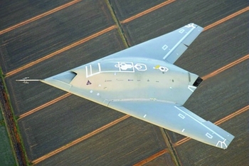
Figure 2. Dassault Aviation Neuron UCAV.
3.3 Taranis
The Taranis technology demonstrator (Fig. 3) is led by BAE Systems in collaboration with engineers from more than 250 companies. It was officially unveiled in 2010 and is designed to operate in sustained surveillance and intelligence gathering missions, as well as carrying out strikes in hostile territories through a combination of advanced aerodynamics, propulsion systems and stealth(25). Initial flight tests took place in late 2013 and early 2014 over the Woomera test range in Australia. Taranis is expected to eventually demonstrate supersonic combat capabilities(Reference Beale26). Building on the knowledge gained from the Taranis and Neuron programmes, the British and French governments announced a cooperative effort in a £1.5 billion project to develop a ‘future combat air system’, the most advanced of its kind(Reference Morales27).
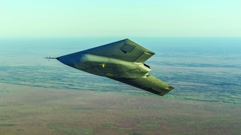
Figure 3. BAE Systems Taranis in flight.
3.4 Others
Several UCAV design projects have been reported to be under development in countries like Russia, India and China; however, concrete information is hard to come by. India's Aura UCAV (Fig. 4) is a lambda wing-type configuration under development by the Indian Air Force and India's Defense Research and Development Organization, expected to become operational by 2023(Reference Pubby28). Russia's MiG Skat UCAV project is believed to be cancelled(Reference Trimble29). The Chinese stealth UCAV demonstrator Lijian (Sharp Sword) (Fig. 5) is believed to be currently under development, with taxi and flight tests taking place in 2013(Reference Hsu30). A comparison of existing and reported UCAV designs is shown in Table 1.

Figure 4. India's Defense Research and Development Organization Aura UCAV early design.

Figure 5. Chinese Lijian UCAV on runway.
Table 1 Summary of technical specifications for existing or reported UCAV demonstrators

4.0 TECHNOLOGY CHALLENGES
The nature of UCAV operational requirements usually results in configurations with stealth considerations being prioritised. Common UCAV designs take the shape of tailless aircraft with swept, highly blended geometries, leading to packaging, aerodynamic, and stability and control couplings that must be accurately evaluated from early design stages if superior manoeuvrability and performance are to be obtained. Furthermore, future capabilities are likely to extend on the operational speeds and manoeuvrability requirements to include supersonic regimes. Therefore, the understanding and correct evaluation of complex flight phenomena is a key aspect in modern and future combat aircraft design(Reference Hitzel and Zimper31).
4.1 Stealth
Stealth features can have detrimental effects in the aerodynamics, stability, performance and overall system complexity of the aircraft. For example, a comparison between the X-47B and a configuration optimised for aerodynamics without taking into account stealth requirements(Reference Taha and Hajj32) shows a result of 10.84 drag counts at cruise for the optimised configuration compared to 122 drag counts for the X-47B, Fig. 6. Neutral stability was also achieved, compared to the negative 0.65% static margin reported for the original configuration. These results would have a significant impact on the range of the aircraft, as well as the required power during cruise, which translates into weight savings and further improvements in the overall performance of the aircraft. However, these results do not take into account packaging or performance constraints, which have a significant impact on the overall configuration.

Figure 6. Aerodynamic and RCS optimisation for a diamond wing UCAV.
The design and development of the F-117 Nighthawk further illustrates the challenges of stealth aircraft. Firstly, it was determined that the main concern for low observability was the radar cross section in the nose-on aspect, followed by the tail-on and side aspects. Due to the radar signature prediction level achievable at the time, and as an limit value from the flight control engineers, the first design iteration took the shape of a diamond wing with a leading-edge sweep of 72° and trailing-edge sweep of 30°, later called by the aerodynamics team as the hopeless diamond. However, this would return a large signature at a 30° offset from the nose or tail aspect. This mandated a change in trailing-edge sweep, and aerodynamics benefitted from decreasing the leading-edge sweep to 67.5°, trailing edge to 48° and an overall increase in aspect ratio, which is very low at 1.65. Also, the payload had to be carried internally, and engines had to be buried with provisions to control radar signature in both inlets and outlets. Communication antennas could only be operated during initial mission segments and retracted afterwards, which limited communications with operating command. Lastly, radar absorbent material had to comply with high temperature requirements for anti-icing of the air data probes(Reference Brown33).
Stealth involves numerous aspects such as visual and acoustic signature, radar cross section, infrared signature, and electromagnetic signature; achieving a truly undetectable aircraft seems improbable. Advances in radar and missile technologies question the relevance of current stealth technologies and design practices. For instance, development in passive radar systems can use the aircraft's actively generated signals such as navigation, identification and data transfer, as well as new illumination sources such as FM radio and digital TV signals to locate and track a target(Reference Manavoǧlu and Yazgan34). Similarly, new Surface-to-Air Missile Systems such as Russia's S-400 have velocities of up to 2,000 m/s and ranges of 400 km with advances in radar technology that resist jamming and other counter-measures(35). Whether these developments render current stealth technology obsolete is still an open debate. Even so, modern aircraft designed for combat and intelligence purposes include stealth measures, especially for radar cross section and infrared signature reduction.
4.1.1 Radar cross section
Radar Cross Section (RCS) is a measure of the amount of energy reflected in a certain direction when an object is illuminated by radar waves. Monostatic RCS is obtained when the transmitter and receiver are in the same location, while Bistatic and Multistatic RCS employ different locations for transmitter and receiver. To measure the real RCS of a complex object, it is necessary to use an anechoic chamber, which ensures a ‘quiet zone’ where the electromagnetic field fluctuations are kept very low(Reference Borkar, Ghosh, Singh and Chourasia36); however, numerical RCS solutions based on physical-optics approximations have existed since the 1980s(Reference Aerospace37), and more recent computational tools include RCSAnsys(Reference Liangliang, Kuizhi, CuiFang and Dazhao38) and POFACETS(39), amongst others.
Reducing an aircraft's RCS can be achieved through a combination of techniques such as geometric and aerodynamic shaping, Radar Absorbent Materials (RAM) and Radar Absorbent Structures (RAS), and electronic counter-measures. Monostatic RCS can be reduced by avoiding edges perpendicular to the incoming radar waves. Inclining and aligning edges will shift the direction of reflected beams away from the incoming source, as seen in Fig. 7 for a delta and a ‘lambda’ wing with aligned edges, so sweeping the wing has a direct advantage in terms of RCS signature. However, this strategy is not as effective for bi-static and multi-static radar systems. Besides sweeping the wing, highly blended geometries with extensive continuous curvatures can further reduce the total RCS signature, which can be seen in aircraft such as the B-2 stealth bomber, F-22 Raptor and the F-35 strike fighter. Figure 8 (Reference Lee, Gonzalez, Srinivas, Auld and Wong40) shows how wing planform and aerofoil changes can influence the signature of UCAV configurations.

Figure 7. Radar wave reflection for perpendicular (left) and inclined/aligned edges (right).

Figure 8. Pareto optimal fronts for UCAV wing/aerofoil optimisation.
Carrying all weapons and payload internally will stop those elements from reflecting and scattering radar waves in multiple directions. Antennas, sensors and other protruding elements, such as geometry discontinuities due to doors, hatches and control surface hinges, should be blended as much as possible to avoid further scattering sources(Reference Ufimtsev41).
Jet engine blades are a major source of reflected radar waves, a way of mitigating this effect is through a buried engine with a serpentine or S-shaped inlet duct, which not only blocks line-of-sight reflection but also has drag advantages since the engine is blended into the fuselage shape. However, the inlet design can cause adverse pressure gradients and separated flows if the geometry is not carefully designed(Reference Johansson42–Reference Zhang, Wang and Lum44). To prevent flow separation in complex inlets, boundary layer suction and bleeds can be incorporated.
RAM can be employed to further decrease an aircraft's RCS; new development in RAM coatings and Radar Absorbent Paint (RAP) can vary their absorbent properties in response to a broadband of frequencies, this technology is called active frequency selective surfaces(Reference Banks, Ito, Kepler and Toivanen45–Reference Tennant and Chambers47). Similarly, composite matrices, like polyester and epoxy, can be enhanced with electromagnetic powders such as carbon black, ferrite and carbonyl iron, to be used as structural components(Reference Oh, Oh, Kim and Hong48). RAS can be load bearing or not; for instance, leading- and trailing-edge sections of the SR-71 Blackbird were composed of fiberglass, phenyl silane and silicone-asbestos to absorb radar waves while bearing no load(Reference Merlin4). Engine inlets should also be coated with RAM or RAP in order to further decrease RCS. For load-bearing structures, it has been shown that a thin plate of glass/polyester enhanced with carbon black (<3 mm) can absorb approximately 90% of the incident electromagnetic wave energy in the X-band frequency (approximately 3.7 GHz) while maintaining its structural integrity(Reference Chin and Lee49).
Electronic countermeasures, commonly known as jamming, are means of deceiving radar systems. Active jammers that send out specific or random signals to convey false information or to keep the channels busy at all times have been around since the 1950s; they are effective but have high power requirements(Reference Neng-Jing and Yi-Ting50). UCAVs flying in formation could use smaller jammers in a cooperative way to increase the overall jamming range and effectively conceal themselves in multiple radar environments(Reference Kim and Hespanha51). Reactive jammers remain idle as long as no incoming signals are being detected, and start transmitting otherwise, which reduces the power required and the probability of being detected by passive radar systems. Their effectiveness has been assessed in wireless networks and satellite communication security(Reference Nguyen, Sahin, Shishkin, Kandasamy and Dandekar52,Reference Lichtman and Reed53) . More recently, digital radio frequency memory technology allows the recording of an incoming radio wave and its modification prior to being sent back in order to convey deceptive information(Reference Gustafsson54) and can be used to greatly reduce a vehicle's RCS signature and radar detection range(Reference Sheng and Yuanming55).
4.1.2 Infrared signature
The infrared signature in an aircraft will make it susceptible to heat-seeking missiles, such as those used in man portable air defence systems and air-to-air missiles. The main contributors to an aircraft's IR signature are the exhaust plume, aerodynamically heated skin, hot engine parts and the reflection of sun, earth and sky shine, as shown in Fig. 9 (Reference Mahulikar, Sonawane and Arvind Rao56). The IR signature will determine the aircraft's lock-on range, which is defined as ‘the locus of points around a target where the missile's IR seeker locks-on to the target’(Reference Mahulikar, Sonawane and Arvind Rao56, p.233). This is not, however, a comprehensive criterion because it does not take into account target and missile speed, or the missile burn-out range. The ‘lethal envelope’ can account for these criteria, and it represents the area around a target where the probability of being hit by a missile is high(Reference Rao and Mahulikar57). Computational IR prediction packages like infrared search and track (Reference Iannarilli and Wohlers58), the NATO Infrared Air Target Model (Reference Noah, Krlstl, Schroeder, Corporation and Sandlord59), and SIGGE(Reference Johansson and Dalenbring60) rely on a combination of theoretical models, field measurements and infrared data sets, and can quickly estimate the IR signature of an object, such as an engine or an aircraft.

Figure 9. Contributors to an aircraft's total IR signature.
IR countermeasures usually translate into weight and system complexity penalties. Passive countermeasures include: masking hot engine parts through geometry or structure modification, mixing hot exhaust gases with freestream air, reducing the reflectivity of the skin through certain coatings and paints, and modifying the skin temperature distribution through physical or chemical means such as liquid evaporation cooling. For jet engines, nozzles with large aspect ratios, defined as nozzle exit width over height, show significant reductions in the IR signature when compared with circular nozzles due to pressure changes in the plume, as well as a more widespread plume, which increases the mixture with cold ambient air, decreasing the overall length of the plume(Reference An, Kang, Baek, Myong, Kim and Choi61); ultimately, this leads to an important decrease in lock-on range, as high as 55%. However, for large-aspect-ratio nozzles, penalties can be as high as a 10% reduction in available thrust.
Active IR countermeasures include: flares, IR jammers, missile approach warning systems, and a ‘sacrificial structure’ which attracts the missile away from any vital structural elements and systems by using an IR decoy, such as an IR lamp mounted on a supporting structure(Reference Czarnecki62).
4.2 Aerodynamics and stability
The use of sweep was originally applied in order to delay drag divergence experienced at high subsonic Mach numbers, and thus improve the aerodynamic performance in transonic regions. This is achieved due to the lower normal velocity component along a wing section for a swept wing, which is equivalent to the cosine of the sweep angle. For instance, for a particular lift condition at transonic cruise speed (M = 0.85), increasing the sweep of a blended wing body (BWB) aircraft from 20° to 40°, shows an 80% increase in the lift-over-drag ratio. This is due to a significant reduction in wave drag by the decreased intensity of local sonic flow over the geometry(Reference Siouris and Qin63). The reduction in perpendicular flow also results in a loss of total lift produced varying proportionally to the cosine squared of sweep angle, according to simple sweep theory(Reference Vos and Farokhi64, chap.8), which can be compensated by the higher velocities achievable. However, it has been shown that this does not agree well with experimental results, as well as not being able to account for the increment in lift due to leading-edge vortices(Reference Chester Furlon and McHugh65).
4.2.1 Delta wing aerodynamics
The flow field of swept configurations is characterised by the formation of leading-edge vortices, as shown in Fig. 10. The low pressure at the vortex core usually translates in beneficial lift characteristics through suction, due to low pressure in the vortex cores, and boundary-layer separation delay(Reference Gursul66). These benefits persist until the Angle-of-Attack (AoA) is high enough for vortex breakdown to occur, which is characterised by rapid flow expansion, sudden change in the velocity field and large fluctuations in the vortical structure(Reference Delery67). For low-sweep delta wings, often called non-slender delta wings (ΛLE<55°), vortex structures develop at lower angles and much closer to the wing surface, resulting in strong interactions with the boundary layer, strong dependence with Reynolds number and leading-edge radius, double vortical structures, and a less violent vortex breakdown process(Reference Gursul, Gordnier and Visbal68). Vortex-related issues applicable to UCAV configurations(Reference Gursul69) include antisymmetric vortex breakdown location, vortex reattachment causing wing rock, and the interaction between manoeuvring and vortex instabilities, which can impact the development flight control laws.

Figure 10. Instantaneous vortex structure for a ΛLE = 50° delta wing.
4.2.2 Validation of numerical methods applied to UCAV designs
Unsteady aerodynamics represents a major challenge for highly manoeuvrable UCAV configurations, impacting the development of flight control systems, and if not identified during the early design process can significantly increase cost and risk during flight testing. For this reason, high-fidelity aerodynamic tools and models are required during the early design process of UCAVs.
Extensive validation efforts have been undertaken by NATO's Research and Technology Organization Applied Vehicle Technology (AVT) group under the AVT-080, -113, -161, -183 and -201 research groups(70–Reference Cummings, Schutte and Hübner73). Quantitative and qualitative data were obtained for a variety of configurations ranging from diamond to lambda wing type ‘generic UCAVs’ through methods such as pressure taps, pressure-sensitive paint, smoke and laser sheet, oil flow visualisation, laser Doppler velocimetry and particle image velocimetry. Similarly, a variety of numerical solutions, such as structured and unstructured grids solving Euler, Reynolds-averaged Navier-Stokes, detached eddy simulations and large eddy simulations governing equations for steady and unsteady state conditions, with several turbulence models, were investigated. Additionally, analytical and semi-empirical models were developed to evaluate the structure and behaviour of vortex breakdown. Variations in leading-edge geometry and dependence on Reynolds number were also investigated.
Figure 11 (Reference Schütte, Hummel and Hitzel74) shows the results from AVT-61 numerical aerodynamic validation efforts over a generic UCAV design with a leading-edge sweep of 53°, known as SACCON. Experimental data are compared to numerical simulations for different turbulence models and grid structures for AoA from 15° to 22° due to the computational resources available. It can be seen that the predicted lift and drag coefficients (solid and dashed lines) show good agreement with the experimental data; however, the predicted pitching moment coefficient shows large disagreements for AoA above 20°. This relates to the complex vortex topology present over the UCAV. At AoA higher than 20°, the vortex topology suffers a significant change; the tip vortex shown in Fig. 11 (top left) is replaced by a large primary vortex (Fig. 11 top right) covering most of the ‘outer wing’ geometry. The same difficulty to predict pitch moment coefficient is reported(Reference Lofthouse, Ghoreyshi and Cummings75) even when expensive numerical solutions are applied. The correct prediction of vortex breakdown has been shown to be a very difficult task, and the deficiencies may be attributed to the lack of appropriate turbulence models(71, chap.34).

Figure 11. Surface pressure distributions and streamlines on the upper side of SACCON for AOAs of 17° and 19°. M = 0.15 and Re = 1.6∙106 (Top). Experimental results compared to numerical simulations for Wilcox–k-ω (left) and Spalart–Allmaras (right) turbulence models.
Similar validation efforts have been applied to Boeing's 1301 and 1303 generic lambda wing designs(Reference Ol76). Figure 12 (Reference Cummings, Morton and Siegel77) shows the evolution of streamlines with respect to AoA; violent vortex breakdown can be seen for AoA higher than 15°. Results also show that a round leading edge has coupled effects with Reynolds number, while sharper geometries are insensitive to it(Reference McParlin, Bruce, Hepworth and Rae78,Reference Shim and Park79) .

Figure 12. Flow field evolution for 1301 UCAV.
Lower-fidelity methods have also been evaluated. These methods consist on potential flow solvers with compressibility and boundary-layer corrections (VSAERO, LIFTING_LINE), panel methods enhanced with leading-edge vortex separation and vortex breakdown models (Nangia-Aero-Panel, dwfs Panel), and vortex-lattice enhanced with empirical models (Tornado VLM, SHAMAN)(Reference Liersch and Huber80,Reference Tomac, Rizzi, Nangia, Mendenhall and Perkins81) . Results show good agreement with lift and drag coefficients for low to moderate AoA; however, results for the pitching moment coefficient vary significantly due to non-linear flow phenomena that low-order methods cannot fully predict. This limits the applicability of such methodologies to the early conceptual design stage.
4.2.3 Stability and Manoeuvrability
Low-speed and high-attitude flight is particularly problematic for UCAV-type configurations. Low-speed wind-tunnel testing of UCAV 1303(Reference Woolvin82) shows the pitch-up behaviour associated with UCAV configurations (Fig. 13), which limits the maximum usable incidence of the aircraft to around 10°. One of the consequences of a low value of maximum incidence is an increase in required speeds for take-off and approach, which could impose higher demands on the engine size, possibly driving the entire configuration. Combinations of twist and camber can be used to increase the maximum incidence and delay the pitch-up behaviour to the point where modern flight control systems can provide enough control in the pitch-up region.

Figure 13. Low-speed pitching moment of 1303 UCAV (M = 0.25).
The vortex flow field of UCAV configurations has a strong influence on control surface effectiveness, as demonstrated experimentally for longitudinal motion(Reference Huber, Vicroy, Schutte and Hubner83), and for lateral motion(Reference Stenfelt and Ringertz84) with conventional control surfaces, i.e. inboard flaps and outboard ailerons, which already require high control power due to the short moment arms of such configurations. For non-conventional control surfaces, simulations including belly flaps and canards show that different control surface combinations can provide the required lift and trim values required for carrier-based operations, with penalties in stealth, mass and system complexity. The trade-offs for choosing the right combination can be appreciated in Fig. 14 (Reference Chung, Hallberg, Cox and Plyler85), where the actuation of belly flaps or canards only cannot achieve the required increment in lift coefficient and must be combined with other control surfaces. Other studies make use of non-conventional control surface arrangements, such as slot-spoiler deflectors, all-moving wing tips, and clamshell elevons, as shown in Fig. 15 (Reference Park, Jo, Yi, Choi, Raj and Choi86).

Figure 14. Trade-off comparisons between different control surface combinations for a BWB-type UCAV.

Figure 15. Non-conventional control surface arrangements for a delta-wing fighter.
Other types of control effectors being studied are active control actuators, which modify the flow and pressure distribution over the aircraft surface. Pairs of pneumatic active flow control actuators are used to effectively provide lateral-directional control of a delta-wing UCAV while also reducing drag for particular attitudes (lift coefficient remains unchanged, which leads to an increase in aerodynamic efficiency and extended range), which could potentially balance the costs of the engine ‘bleed’ that these types of actuators requires(Reference Williams and Seidel87).
At transonic speeds and high AoA, conditions easily encountered during combat manoeuvres, the vortex dominated flow field interacts with local sonic flow, which forms complex shock wave systems at Mach numbers as low as 0.7. These shock waves affect the formation of vortices and can significantly increase the flow separation extension as Mach numbers approach sonic conditions. The extent of shock-induced separation can be attenuated by tailoring the twist and leading edge radius distribution along the span of the configuration(Reference Zimper and Rein88).
4.3 Structures
4.3.1 Composite materials
UCAV designs optimised for stealth and aerodynamic efficiency result in complex geometries, which makes them ideal candidates for implementing the use of composite materials and advanced manufacturing techniques such as the foam matrix core process used in the X-45A wings(89). In the case of the X-47B, 90% of its surface is made out of composite skins, as well as a significant part of its outer wing structure(90). New high-temperature composites based on polyimide, bismaleimide and cyanate ester matrices are being used in the ‘hot zones’, such as engine components and possibly in future high-speed vehicles where aerothermal phenomena are important design constraints(Reference McConnell91,Reference McConnell92) . The main advantage of integrating composite materials is a significant weight reduction with equivalent or superior stiffness properties. Advanced manufacturing techniques also reduce the number of assembly components, further reducing weight and overall complexity. Furthermore, a wide variety of sensors can be directly embedded into the composite plies in order to provide in situ structural health monitoring capabilities. Optical sensors such as fibre Bragg gratings have been shown to accurately detect and monitor fatigue crack growth in composite adhesive joints when compared to other techniques such as ultrasonic testing; for a comprehensive review of optical sensors in composite structures, see Ref. 93.
One of the main disadvantages of switching from electrically conductive metallic alloys to insulating composite materials is the higher probability of lightning strike damage, which can cause embrittlement, delamination, resin evaporation, and finally structural failure. Current Lighting Strike Protection (LSP) in composite structures is provided by bonding a mesh of aluminium or copper to the outer composite surface, providing enough electrical conductivity. However, this mesh increases structural weight and diminishes the weight-saving advantages of composite airframes. Possible future LSP solutions include carbon-based materials such as carbon nanotubes, graphene and graphite added to the composite matrix to increase it mechanical, thermal and electrical properties. Additionally, metallic coats can be applied to composite structures in order to achieve the required thickness and conductivity for sufficient LSP levels. Other challenges of LSP include reparability and maintenance. A review of regulations concerning lightning strikes, as well as prospects for metallic and carbon-based materials and techniques for advanced LSP solutions can be found in Reference Gagné and TherriaultRef. 94.
Another important challenge for composite structures is impact damage resulting in composite delamination. Low-velocity impact damage can result from foreign-object damage and maintenance errors (such as tool drops). Delamination effects are particularly critical for structural components loaded under compression because buckling behaviour can propagate the extent of delamination cracks, which in turn severely affect the mechanical properties, leading to premature collapse of structures, as shown in Reference Kutlu and ChangRef. 95 for single- and multi-delamination composite panels. For this reason, it is important to develop analysis and management strategies for delamination growth prediction. Numerical delamination growth monitoring strategies developed in Reference Riccio, Raimondo and ScaramuzzinoRefs 96–Reference Perugini, Riccio and Scaramuzzino98 for large deformations and non-linear geometrical effects, as well as contact influence, confirm a significant reduction in global buckling load for composite panels when delamination is present.
Finally, combat aircraft often suffer battle damage, which can take the form of holes from ballistic damage or shrapnel damage on the skin of different parts of the aircraft. Generic composite repair techniques investigated by NASA and the Northrop Corporation during the 1970s and 1980s showed that the structural integrity of composite structures could be restored without the use of expensive or special tools(Reference Myhre and Labor99). More stringent aircraft battle damage repair specifications limit the applicability of repair techniques such as prepreg tape and film adhesive due to their need for freezer storage. Hand lay-up methods can be used but introduce large porosities due to trapped air and resin reaction gasses. Pre-cured hard patches bonded with adhesive paste can be used, but their low carrying capability also limits their applicability. A promising solution is vacuum infusion repairing. By using portable curing units, low-viscosity resins and a novel brittle-bond area reinforcing technique, vacuum infusion has been shown to be suited for aircraft battle damage repair of composite structures(Reference Tzetzis and Hogg100).
4.3.2 Aero-structural interactions
The interaction between a flexible structure and the complex vortex topologies characteristic of delta wings has been demonstrated experimentally(Reference grey, Gursul and Butler101) and numerically(Reference Attar, Gordnier and Visbal102) for slender and non-slender wings, concluding that vortex flows can cause wing buffeting and large aeroelastic responses. Therefore, it is necessary to incorporate aeroelastic considerations during the early design stages. This is most commonly achieved by using numerical simulations packages linked between aerodynamic and structural computations. MSC NASTRAN includes a doublet lattice method that provides pressure coefficients with which aerodynamic loads can be applied to a structural mesh, as shown for a UCAV structural optimisation study(Reference Voβ and Klimmek103). Similarly, computational fluid dynamics and finite element analysis computations are linked through the Deutsches Zentrum für Luft-und Raumfahrt's in-house TAU code for steady aeroelastic analyses of a generic UCAV configuration, revealing its behaviour with changes in Mach and AoA(Reference Voss, Cumnuantip and Neumann104), as shown in Fig. 16. Results show that aeroelastic deformation has significant effects in the development of vortex flow topology at high speeds and AoAs, and thus in the development of lift and drag coefficients. Examples of aero-structural coupling strategies for the application of manoeuvre loads on a generic flying-wing UCAV structure model is shown in a DLR study, including control surface trim effects(Reference Voss and Klimmek105).

Figure 16. Aeroelastic deformation of a UCAV configuration at various Mach numbers and AoA.
4.3.3 Other structural considerations
Some operational constraints have a direct impact on the structure of the vehicle. For instance, some supportability requirements mandate the transport of UCAVs on military cargo aircraft such as the C-5 or C-17, which limits the maximum wingspan to around 5.5 m, that along with long-term storage (up to 10 years) requires a modular design, as shown in Fig. 17 by the truncated wings(Reference Chapman106), while also emphasising the need for careful material selection.

Figure 17. UCAV long-term, humidity-controlled storage concept.
4.4 Packaging
Packaging is a multi-disciplinary challenge which impacts the aerodynamic, stability, performance and operational capabilities of the vehicle, and more so for highly constrained vehicles such as UCAVs. To illustrate the point, longitudinal stability is enhanced by densely packing the nose area of a lambda-wing UCAV with some systems and avionics components, as shown in Fig. 18 (Reference Levy, Katz, Katzuni, Konevsky, Frumkin and Buium107). Similarly, the Storm Shadow UCAV shows an awkward and complicated landing gear retraction for both the nose and main landing gear, in order to fully accommodate the avionics and systems required (Fig. 19)(108). Tight packaging can also have significant effects on aircraft maintenance and operational costs. The detailed transparency of the Neuron UCAV shown in Fig. 20 (Reference Pocock109) exemplifies this issue. The complex and stealthy engine inlet design can also be seen quite clearly.

Figure 18. Cerberus UCAV systems arrangement.

Figure 19. Storm Shadow UCAV internal arrangement.

Figure 20. Neuron UCAV computer assisted design model transparency; a high-density packaging area can be seen above the engine inlet.
Internal weapon bays are not only a packaging issue, but they can also result in severe aero-acoustic interactions, which can compromise the structure of the aircraft, and any equipment contained in them, as well as having adverse performance and handling characteristics when activated at high speeds(Reference Chaplin and Birch110).
During the early conceptual design process, the class shape transform proposed by Kulfan(Reference Kulfan111) can be used as an efficient geometrical parametrisation strategy and can be employed to include volumetric and packaging constraints during multi-disciplinary design optimisation of BWB aircraft(Reference Morris, Allison, Schetz and Kapania112–Reference Straathof, Van Tooren, Voskuijl and Vos114).
4.5 UCAV conceptual design studies
The vast majority of UCAV conceptual design studies found in the literature(Reference Lee, Gonzalez, Srinivas, Auld and Wong40,Reference Liersch and Huber80,Reference Woolvin82,108,Reference Woolvin115–Reference Lee, Gonzalez, Srinivas and Periaux125) take the form of flying wing configurations fulfilling ground strike–type missions, with cruise speeds in the transonic region; from Mach 0.7 up to Mach 0.85. Low observability requirements, most commonly in terms of RCS considerations, often dominate the configuration choice in terms of sweep and absence of vertical control surfaces. Dash or ingress/egress segments take place at low to medium altitudes (100 m up to 5 km) for short distances and at higher speeds well into transonic regimes, usually close to Mach 0.9, some allowance for combat manoeuvres is occasionally specified during the dash and weapons release segments, which often drives the maximum normal acceleration manoeuvring limit up to values of 7.5 g. Payloads go from 400 kg up to 2,000 kg, always carried internally due to low observability constraints. This type of mission can be generalised as shown in Fig. 21. Cruise segments are usually specified in terms of optimum speed and altitude for fuel savings.

Figure 21. Strike mission schematic.
Conceptual design methodologies commonly include a wide range of fidelity levels for multi-disciplinary design analysis and optimisation (MDAO), from empirical models and regression constants to surrogate models through response surface methods derived from high-fidelity data resulting from wind-tunnel and numerical computations. In most cases, a particular baseline configuration undergoes an optimisation study in order to expand mission capabilities, where the driving requirements are often mission combat radius, payload mass and field performance requirements. As shown in the 1303 UCAV studies(Reference Woolvin82,Reference Woolvin115) , poor aerodynamic and stability performance, namely the low value of maximum allowable incidence prior to pitch-up behaviour occurs, combined with field performance requirements often drive the entire size of the configuration. Field performance requirements impose larger engines, more fuel, and a larger centre section length (for internal engine housing), which increases structural mass, further driving the engine requirements higher. Stability constraints drive the UCAV design shown in Reference AndersonRef. 122 where an inverted engine installation is investigated. It is shown that this option increases the lift coefficient in order to comply with pitch trim requirements while also improving lift at lower speeds; however, the engine performance is severely affected due to the complex inlet geometry, resulting in an oversized engine.
A different approach is taken in the pre-conceptual design survivability analysis presented in Reference Ahn, Lee and KimRef. 124, where flight speed and manoeuvring load factor are the main design outcomes. In this study, the mission requires the UCAV to hit a SAM missile launch site. A target volume is determined by combining SAM performance data, UCAV flight path, speed and evasive manoeuvring capabilities, obtaining a probability of kill, which is defined as the combined probability of the UCAV being hit, and the probability of kill when hit. Figure 22 shows Pareto solution sets for probabilities of success (as outcomes of uncertainties in the modelled performances of both UCAVs and SAM systems) expressed in terms of standard deviations (σ) imposed on particular kill probabilities as a function of aircraft performance. From the figure, a probability of success of 99.99% (3σ) limits the aircraft performance to flight speeds of Mach 1.32 up to 1.5 and instantaneous turn rate from 11.4 g to 13.1 g; this solution also shows a maximum kill probability of 10%. In this way, a kill probability threshold can be defined as a design requirement, flight performance can be determined, and the designer can incorporate such performance levels during the early conceptual design process.

Figure 22. Effect of stealth requirements on UCAV configurations.
An interesting technology-level impact study is shown in Reference Mavris, Soban and LargentRef. 123 for a UCAV design that is not a flying wing or BWB type but rather closer to an advanced manned fighter design. This study can integrate ‘advanced technology scenarios’ for particular disciplines to determine the impact in the overall design. As an example, a higher use of composite materials reduces structural mass, improves performance and also increases development costs significantly. Large sensitivity analyses can be generated using this procedure, which reveals important information for decision makers in terms of particular technologies that require accelerated development efforts.
A multi-objective optimisation study aimed at a strike UCAV(Reference Lee, Gonzalez, Srinivas, Auld and Wong40) shows the type of trade-offs designers can expect when considering different mission segments and their influence on performance and structural parameters. The objectives are (1) maximise aerodynamic efficiency at cruise; (2) maximise aerodynamic efficiency at transonic, low-altitude ingress/egress; and (3) minimise the wing-bending moment during ingress/egress segments. Potential flow solvers FLO22 and FRICTION provide aerodynamic data, and the design inputs are wing planform and aerofoil control points. A multi-objective evolutionary algorithm coupled with a Pareto tournament strategy is used to obtain the non-dominated Pareto fronts, as shown in Fig. 23. It can be seen that lower values of wing-bending moment (Obj3) correspond to lower values of lift-to-drag ratio at both cruise and ingress/egress segments, which can be expected due to the lower lift being produced.

Figure 23. Pareto solution sets for particular kill probabilities vs flight speed and instantaneous turn.
5.0 AIRWORTHINESS AND NAVIGATION
Some of the key challenges identified in the operational constraints and certification of unmanned vehicles are: safety strategies for autonomous navigation such as detect and avoid capabilities, human systems integration, privacy concerns held by the public, and security implications. To overcome these difficulties, proper standards and minimum operational requirements for all classes of unmanned vehicles must be developed(126).
5.1 Integration into the airspace
The first efforts towards UAV regulation and integration into civil airspace systems date back to 1991, with the HALE UAV certification roadmap undertaken by the Federal Aviation Administration (FAA) along with partners in academia and industry. Today, certification for unmanned systems are still temporary measures all across the globe(Reference Dalamagkidis, Valavanis and Piegl127).
In the United States, unmanned aerial system operations are authorized case by case through a special airworthiness certificate under the experimental aircraft category and a certificate of authorization(128) as mandated by Order 8130.34C(129). Up to October 2016, a total of 74 certificates of authorization have been granted by the FAA to government institutions such as the Air Force Research Laboratory, law enforcing agencies such as the Customs and Border Patrol, universities and research centres such as the Washington State Department of Transportation, and environmental agencies such as the U.S. Department of Agriculture – Forest Service(130).
In the United Kingdom, the Autonomous Systems Technology Related Airborne Evaluation and Assessment programme seeks to include unmanned aircraft in all classes of airspace without restrictions or special conditions by developing key enabling technologies and procedures(131). For the rest of Europe, the European Aviation Safety Agency along with THE Joint Authorities for Rulemaking on Unmanned Systems must regulate civil operations of UAVs over 150 kg under Regulation (EC) No 216/2008, which dictates how standards and certification policies must be generated(132). For military purposes, NATO's STANAG 4671 establishes baseline airworthiness standards for the design and construction of UAVs(133).
Chinese regulation allows any UAV weighing less than 7 kg to be flown without any kind of license or certificate, UAVs between 7 and 116 kg require a license from the Civil Aviation Administration of China (CAAC), and for UAVs heavier than 116 kg to be operated in the airspace where manned aircraft fly, operators must have a pilot license and authorization from the CAAC. This, however, seems to be an initial measure towards integrating unmanned operations into the airspace(134).
The impact of large unmanned aircraft in the civil airspace is currently being evaluated through large-scale simulations, human and hardware in the loop tests, and flight tests with virtual and real UAVs(Reference Johnson, Mueller and Santiago135–Reference Jenie, Van Kampen, Ellerbroek and Hoekstra137). The test flight shown in Fig. 24 represents the UAV path in an airspace sector where simulated, historical and real-time air traffic was included. These simulations also allow engineers and policy makers to compare certain safety strategies, definitions, and metrics such as ‘well clear’, ‘separation assurance’ and other separation standards, which will in turn feed into the regulatory frameworks in the form of minimum performance and operation requirements.

Figure 24. UAV flight path mapped from restricted airspace sector 40/41 into virtual airspace for flight test demonstration.
The continuous development of small, light-weight UAVs and their increased areas of application require new approaches towards unmanned operations. NASA's Unmanned Aerial System Traffic Management project seeks to develop concepts and technologies that enable operations in low-altitude, variable-risk areas, from rural to urban, through a combination of live operations and virtual human in the loop simulations. This project will also develop key software components to gradually increase the complexity of the simulations, analysis and air traffic management capabilities across the airspace system(Reference Prevot, Rios, Kopardekar, Robinson, Johnson and Jung138,Reference Prevot, Homola and Mercer139) .
5.2 Automatic navigation
Automatic navigation is an intense area of research at present, and some of the major challenges are: Sense And Avoid (SAA), adaptive task assignment and path planning, fault-tolerant control, and formation flight strategies.
UAVs are expected to be able to safely operate in all kinds of airspace conditions, this means detecting and avoiding collisions in cooperative (aircraft with communication equipment such as TCAS II or automatic dependent surveillance-broadcast) and non-cooperative scenarios (detection of other aircraft via LIDAR or electro-optical sensors) through a variety of strategies. SAA technologies are the target of extensive research(Reference Yu and Zhang140).
Autonomous routing and task assignment solutions can be achieved through solving complex problems such as vehicle routing and the travelling salesman problem(Reference Harder, Hill and Moore141). Tabu search heuristics and receding horizon control techniques can account for ‘pop-up’ threats and moving targets, and have been successfully applied to combat simulations, although these strategies can be adopted for civil applications(Reference Shetty, Sudit and Nagi142,Reference Zhang, Chen and Shen143) .
Formation flight is highly dependent on SAA technologies. Several strategies have been proposed, such as the distance-error based algorithms for leader-follower scenarios(Reference Boskovic, Mehra and Li144,Reference Kang, Park, Lee, Ahn and Graph145) , multi-agent swarm formations(Reference Zhu, Liu and Yang146), and a completely different approach based on digital pheromones inspired on electrostatic and gravitational field dynamics(Reference Parunak, Purcell and O'Connell147), among many others. These strategies share the need for robust communications and reliable sensors.
Command, control and communication technologies are essential for unmanned operations in permissive and non-permissive airspace(Reference Stansbury, Vyas and Wilson148). NATO STANAG 4586 aims to provide interoperability standards for UAV communications and bandwidth requirements(149).
Increased autonomy levels in UAVs result in fundamental changes on the relationship between the operator and machine. Permitted autonomy levels, information exchange requirements and human-machine interface requirements should form the base of the control philosophy behind UAV and UCAV operations. Pilot authorisation and control of tasks levels show that areas such as planning and tactics offer great potential for co-operation between the operator and machine, while health monitoring and self-defence would strongly benefit from a highly autonomous system(Reference White150). Increasing autonomy would also lead to reduced bandwidth and energy demands for communications, allowing the command of multiple vehicles by a single operator(Reference Cummings, Bruni, Mercier and Mitchell151).
6.0 ETHICAL CONCERNS
6.1 Surveillance
The use of UAVs is now fairly widespread and current applications include public security, law enforcement, border patrol, emergency services, and civil and commercial uses, such as remote sensing for smart agricultural practices. It has been shown that current surveillance-related legislation does not account for the variety of applications and technologies integrated into unmanned aircraft, as opposed to other surveillance equipment like closed-circuit television and communication interceptions(Reference Finn and Wright152). A risk perception study carried out in Australia identified privacy violations resulting from the use of unmanned vehicles as one of the main concerns held by the public(Reference Clothier, Greer, Greer and Mehta153).
6.2 UAVs in combat
The main ethical concerns on the use of UAVs in combat and strike roles are:
-
1. UAVs encourage early use of force due to the lack of risk to human operators.
It has been argued that UAVs are not transformative in the sense that they offer no strictly unique capabilities when compared to manned combat aircraft(Reference Davis, McNerney, Chow, Hamilton, Harting and Byman10), and they have been proven to be extremely vulnerable to all kinds of enemy threats, which limits how early current UAVs can be used in conflict(Reference Haider154).
-
2. The morality behind autonomous operations is unclear, especially when it comes to target identification and engagement.
Automatic target recognition algorithms are currently under intense research focus due to the reported ‘(unacceptably high) false-alarm rate of both human and machine-based radar image recognition’(155). However, countries that operate UAVs in combat roles are ‘committed to retaining human oversight over all weapon-release decisions’ and to subject their crew to ‘stringent rules of engagement that ensure lawfully used armed force’(156, p.2.9).
-
3. UAV operators are detached from the reality of combat, usually called the ‘video-game effect’ or ‘play-station effect’.
Due to sustained surveillance capabilities provided by UAVs, operators are able to observe the target area and evaluate its validity for longer periods of time without the physical and psychological strain of combat pilots, reducing decision errors. There is plenty of testimony from operators and military commanders emphasizing the realism of remote operations; for instance, Air Force Major S. Rogers says that “Physically, we may be in Vegas, but mentally, we're flying over Iraq. It feels real”(Reference Sparrow157).
-
4. The policies behind drone strikes are not fully disclosed due to matters of national security, which could make them susceptible to abuse.
Signature strikes are characterised by targeting groups whose behaviour corresponds to that associated with terrorist activity, even when their identities are unknown. Intelligence data gathered exclusively through unmanned vehicles serving ISR roles can lead to misinterpretation of the suspects’ behaviour. Even though this argument focuses on the policy and not on the vehicles themselves, designers and engineers can include a certain degree of ethics during the design process through advanced sensors, robust communications and a clear chain of responsibility(Reference Sparrow157). Paradoxically, characteristics inherent to UAVs (sustained surveillance capabilities, advanced sensors, real-time communication) that would enable them to comply with international humanitarian law seem to ease the infringement of these same laws. Although this is just a tentative statement, the argument is compelling when observed through cognitive consistency and misperception theories(Reference Martin158). This is perhaps the most compelling argument against the use of unmanned aircraft in combat roles.
-
5. Lack of information on strike effectiveness makes it difficult for international humanitarian law agencies to monitor operations.
The real number of civilian casualties is hard to determine due to security reasons and dangers proper to the areas of conflict. Mainstream media seem to underreport the number of casualties when compared to data from the International Bureau of Journalism(Reference Bachman159). However, a case has been made by local (to the conflict zone) researchers against the ‘inflated’ number of reported civilian casualties and the negative opinion on drone strikes held by locals(Reference Taj160). A database which compiles UAV strike data over Pakistan from 2004 to 2007 shows that UAVs result in 17 to 1 militant to civilian casualty ratio, compared to an alarming 0.125 to 1 militant to civilian ratio estimated in all other armed conflicts in the year 2000(Reference Plaw161).
Finally, a compelling argument in favour of the use of UAVs in combat is presented by introducing the principle of unnecessary risk, which demands that ‘no more risk than is required for accomplishment of G (G being a good or just goal) (. . .) is ordered by X to be incurred by Y’. From this, it follows that if the goal is good and justifiable the use of unmanned aircraft is not only necessary but morally obligatory(Reference Strawser162).
7.0 CONCLUSIONS
This paper has briefly summarised the historical background of unmanned vehicles in military uses and the reasons behind the evolution towards UCAVs. The main technology demonstrator programs currently under development were also discussed, and due to the nature of the projects, most of the detailed technical information is not publicly available. As it can be seen from the technological challenges section, UCAVs are highly constrained designs that require a high-level multi-disciplinary integration from the earliest design stages in order to accurately match the operational requirements with their impacts on the configuration. The tendency of UCAV designs to be that of a delta wing, lambda wing or BWB is due to the tendency of stealth requirements to dominate.
The inclusion of good stealth characteristics in terms of RCS and IRS signatures impacts the aerodynamics, performance, packaging and system complexity of the configurations. Fast and accurate prediction tools of the complex aerodynamic and stability interactions for a wide range of operational speeds and attitudes are vital in UCAV designs. Aeroelastic considerations must be included during the early design stages due to the interaction between the complex vortex flow topology and the structure of the aircraft. Composite materials offer significant weight saving advantages and the opportunity of aeroelastic tailoring; however, lightning strike protection and in-field reparability must be carefully analysed. Packaging constraints are of significant importance; employing good design practices, such as efficient geometric parametrisation, can address some of these issues during the early conceptual design stages.
Multi-disciplinary design analysis and optimisation frameworks are a common practice during the initial design studies for UCAVs. A variety of fidelity levels are used during early design studies, with common methods being empirical models, regression analysis and low-order numerical solvers such as vortex lattice or panel methods for aerodynamics and stability. The majority of conceptual design studies aim at developing subsonic configurations for strike missions, with cruise and dash speeds well into the transonic region. Payloads rarely surpass 2,000 kg and are usually specified in particular weapon requirements. Some of the reported main constraints for UCAVs are the low maximum allowable incidence due to pitch-up phenomena encountered, which impacts field performance constraints and engine sizing, which results in heavier aircraft with a larger centre section for buried engines.
In terms of airworthiness and certification, several provisional standards and rules have been pushed forward by the main aeronautic authorities around the globe. The impact of unmanned aircraft on the airspace, as well as safety metrics, is being evaluated through large simulations and flight tests. This information will feed into the required policies and standards for unmanned operations in the civil airspace systems.
To ensure the safety of unmanned operations, both in civil and military roles, demand extensive research in areas such as sense and avoid, formation flight, automated task assignment, and flexible command, control, and communication (C3) architectures.
On the ethical aspect, the main public concern is the violation of privacy resulting from unmanned aircraft operations. The most relevant arguments against the use of UAVs in combat scenarios are the early use of force due to the lack of risk to human operators, the so-called ‘video game effect’, signature strike policies, and the lack of transparency on unmanned operations and their effectiveness. As it happens with any new technology, cooperative and multidisciplinary efforts between policy makers, defence authorities, industry, and international law organisations are the key to enabling UCAV operations while at the same time abiding by international humanitarian laws.


