


1.0 INTRODUCTION
Service life is one of the most important indices of aircraft structure. In order to ensure flight safety, the service life is actually a life limit with high reliability(Reference Kim, Sheehy and Lenhardt1). The determination of the life limit has been widely discussed to ensure the aircraft used safely and economically(2–Reference Ren, Zhang, Jiang, Zhang and Sun6). For example, the Aircraft Structural Integrity Program (ASIP)(2), which provides a framework widely used in air forces worldwide for establishing and sustaining structural integrity throughout the aircraft's life.
There are three main approaches currently in use to manage the aircraft structural life: safe life, damage tolerance and durability. The safe life requires that there is a low probability for a structure in which the strength will degrade below its design ultimate value due to fatigue cracking during the flight time(2). The damage tolerance permits a structure to retain its required residual strength for a period of unrepaired usage even if it had an initial flaw or defect(Reference Grant7,Reference Nesterenko and Nesterenko8) . The durability is the ability of the aircraft structure to resist cracking, corrosion and other damages for a prescribed period of time(2).
In reality, the structural life of an aircraft is affected by its in-service environment, which relates specifically to issues of corrosion and cyclic loading. The corrosive environment will decrease the cracking resistance of a structure, and flight loading will cause fatigue damage to the structure( Reference Hoffman and Hoffman 9 - Reference Bellinger, Liao and Benavides 13 ). Therefore, some U.S. military standards and handbooks, such as the MIL-STD-1530C(2), MIL-STD-810G(14), AFRL-VA-WP-TR-2003-3002(Reference Miedlar, Berens, Gunderson and Gallagher15), etc., take the issue of corrosion into account in aircraft production and usage. Many investigators also have devoted to the research of corrosion fatigue issues of aircraft( Reference Harlow and We 16 - Reference Rokhlin, Kim, Nagy and Zoofan 23 ).
In China, there are two indices to limit aircraft structural service life: fatigue life (expressed as flight hours) and calendar life (expressed as service years)(Reference Liu and Li24,25) . The service calendar life is the service years of aircraft in which the aircraft can meet design requirements safely and economically in the service environment and conditions(Reference Zhang40). The service calendar life of a structure has three elements involving service environment and conditions: the life of a surface's protection coating; the life of a material without a surface protection coating; and economical maintenance life (inspection, repair or replacement of the critical components). The service environment includes temperature, humidity, vibration and so on. The service conditions include flight loadings, maintenance conditions, storage conditions and so on. The service calendar life has been widely researched. D. Zhang(Reference Zhang26,Reference Zhang27) presented the definition and determination method of calendar life. F.Z. Zhang(Reference Zhang28) established a method of area determination of an aircraft's calendar life. In the actual use process, the fatigue life and calendar life are used, respectively; the aircraft will be retired if either of the two indices reaches its prescribed values, which were determined before the aircraft started service(Reference Liu and Li24). However, the fatigue life limit and calendar life limit are usually not matched very well, which may result in huge waste of aircraft structural life potential or unsafe states of some structures.
Actually, the flight strength and the service environment of an aircraft are not fixed, and the safe limits of the fatigue safe life and calendar life changing during use. Based on analysis of aircraft structural life investigations and the determining process, and considering the interaction between fatigue life and calendar life, we have put forward a concept called the Aircraft Structural Life Envelop (ASLE) to manage service life by using life scopes of fatigue life and calendar life(Reference He29,Reference He, Fan, Li and Li30) . The general idea to establish the ASLE has been proposed(Reference He and Fan31) and the theory of service life supervision for individual aircraft structure has been given(Reference He32). However, these studies are only the primary ideas, and specific steps have not been developed after the establishment or the application of the ASLE.
In this paper, specific steps to establish and to apply the ASLE are developed based on the former studies. A residual life prediction method for aircraft structure under service environment is established by combining the ASLE with the Miner theory, and a service life extension method of aircraft structure is put forward based on scope extension of the ASLE. Finally, an application example of the ASLE is presented by using the skin structure of a type of aircraft services in a certain environment.
2.0 CONCEPT OF THE AIRCRAFT STRUCTURAL LIFE ENVELOP
ASLE is a safe and reliable life scope for aircraft structures in service. It can be described in a two-dimensional Cartesian coordinate by using the fatigue life as the vertical axis and the calendar life as the horizontal axis. The ASLE reflects the interrelationship between limits of fatigue life ( Nf , in flight hours) and limit of calendar life ( Ny , in years). When an aircraft is used so heavily that it exceeds the limit of ASLE, the structural state is considered to be unsafe. That is to say, the flight envelope(Reference He, Fan, Li and Li30) ensures the safety of each flight of an aircraft, while the ASLE ensures the safety of an aircraft throughout its service life.
Figure 1 shows a schematic diagram of typical ASLE, which only describes the life limits of an aircraft grounded in a certain environment. In this diagram, both directions of the horizontal axis ( Ny ) are positive; they are calendar lives under different states of protective coating. The abscissa value of Tp is the effective period of protective coating; structures can be considered to be suffering from pure fatigue damage in this period. The point Np represents the fatigue safe life with high reliability in non-corrosion conditions. This parameter can be obtained through component or full-scale fatigue tests and reliability analyses. The curve Np –Aʹ reflects change laws of the fatigue safe life of structures in the corrosive environment without the protection of a protective coating. The line Aʹ–Nc is a limit boundary to prevent an unexpected fracture of a structure due to corrosion fatigue damage. It relates to the demands of static strength and fracture characteristics in a corrosive environment, and the demands of economical repair of aircraft etc.
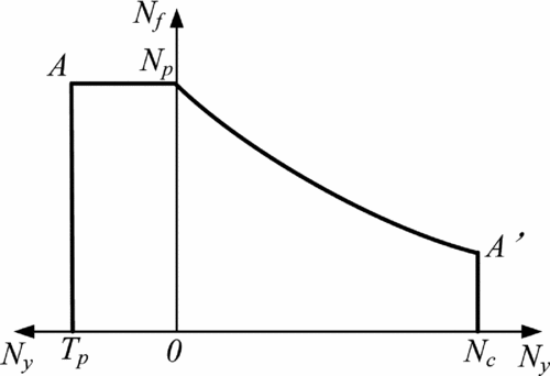
Figure 1. Typical ASLE of an aircraft grounded in one environment.
The typical ASLE shown in Fig. 1 can be used to predict residual lives of structures suffering both cyclic loading and corrosion in a certain environment. If a structure only suffered from cyclic loading or corrosion, the related ASLEs, which have no limit on the direction of calendar life or fatigue life, are shown in Figs 2 and 3, respectively. In reality, an aircraft is usually used in different regions and grounded in different environments; therefore, different ASLEs for these environments should be used to predict structural residual life. For example, four ASLEs for different environments are shown in Fig. 4. They can be used to predict the residual life of an aircraft structure which has served in these climates. The more corrosive the environment, the smaller the scope of ASLE becomes.
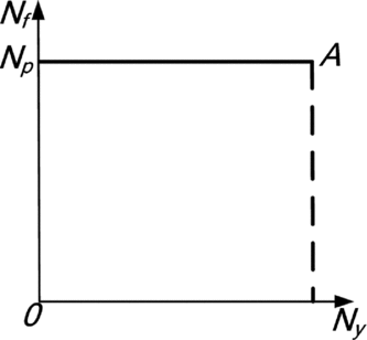
Figure 2. ASLE of a structure suffering only cyclic loading.

Figure 3. ASLE of a structure suffering only corrosion.

Figure 4. ASLEs of aircraft services in different environments.
3.0 ESTABLISHMENT OF THE AIRCRAFT STRUCTURE LIFE ENVELOPE
Life limits of an aircraft are established based on the limits of the airframe and its critical components. Consequently, the ASLE for a critical component is usually established to manage the service life of the aircraft.
First, it needs to be explained that the establishment of ASLE is based on the baseline load spectrum. The baseline spectrum is an update of the design spectrum based on measured data from operational aircraft(2) that represents the actual or average use of the aircraft fleet. The degree of damage for actual loads the aircraft undergoes is usually different from that of the baseline load spectrum. Consequently, the flight time under the actual flight load should be converted into the equivalent flight time under the baseline load spectrum when the ASLE is used to manage the service life of the aircraft. The equivalent flight time also can be called the baseline service time. To consider the effects of the corrosive environment on the life quality of an aircraft structure, the ASLE can be established as follows.
As shown in Fig. 1, the left and right parts of the ASLE can be established through corrosion tests of coating specimens and corrosion-fatigue tests of unprotected specimens in a laboratory, respectively.
Step 1: Determination of the effective period of the protective coating (Tp )
In the service period of an aircraft, the protective coating will deteriorate gradually due to the effects of temperature, humidity, corrosive atmosphere, ultraviolet radiation and so on. The protective coating can prevent the base material of the aircraft structure from corroding, and the structures can be considered to be suffering from fatigue damage only when the protective coating is effective.
The effective period of protective coating (the abscissa of Tp ) can be determined by equivalent corrosion tests of coating specimens in laboratory experiments under conditions simulating actual service environments.
Step 2: Determination of the fatigue safe life (Np )
The point Np in Fig. 1 is the fatigue safe life with a reliability of 0.999 and a confidence level of 0.9 when the fatigue life follows the log-normal distribution. The Np can be determined by fatigue tests under the baseline load spectrum and by reliability analysis.
After the determination of Tp and Np , the left part of the ASLE, which reflects the safe life scope for the critical component during the effective period of the protective coating, can be established.
Step 3: Determination of the corrosion effect coefficient curve (C(T) curve)
For most of the service time, the military aircraft are grounded on land or carriers. For example, if an aircraft is designed to be used for 20 years and 3,000 flight hours, the flight time accounts for only 1.71%. Because the corrosion properties relevant to high altitudes (over 3,000 m) can be ignored, the grounded aircraft can be considered to suffer only corrosion, and the flight aircraft can be considered to suffer only fatigue damage. Consequently, the influence of the grounded environment on the fatigue life can be determined through corrosion-fatigue tests.
The C(T) curve, which is also called the corrosion effect coefficient curve(Reference Liu, Li and Jian33,Reference He, Liu and Xiang34) , represents the effect of corrosion on fatigue life. It can be determined by pre-corrosion fatigue tests or by alternative corrosion fatigue tests of unprotected specimens. The equivalent environmental spectrum and the baseline load spectrum should be used in the corrosion-fatigue tests.
Any point on the C(T) curve can be determined by Equation (1)
 $$\begin{equation}
C(T) = \frac{{{N_{99.9}}(T)}}{{{N_p}}}
\end{equation}$$
$$\begin{equation}
C(T) = \frac{{{N_{99.9}}(T)}}{{{N_p}}}
\end{equation}$$
where Np is the fatigue safe life under the baseline load spectrum without corrosion, N 99.9(T) is a fatigue safe life with a reliability of 0.999 and confidence level of 0.9 after equivalent T years of pre-corrosion or accumulating corrosion.
The C(T) curve can be fitted as(Reference Liu and Li24)
 $$\begin{equation}
C(T) = 1 - a{T^b},
\end{equation}$$
$$\begin{equation}
C(T) = 1 - a{T^b},
\end{equation}$$
where T is equivalent corrosion years, a and b as fitting coefficients.
Step 4: Determination of the limit boundary for safety (Aʹ–Nc )
With increases in service time, the quality of aircraft structures decreases. Corrosive environment and cyclic loading may lead to unexpected fractures of the structure. In order to prevent the occurrence of this safety issue, the limit boundary must be determined.
This boundary relates to the demands of the static strength, the fracture characteristics in the corrosive environment, the demands of economical mend and so on. For example, for the demand of static strength, the maximum flight load is enlarged by 150% to validate the conditions of corroded structures.
Step 5: Establishment of the right part of the ASLE
The right part of the ASLE can be fitted by multiplying the fatigue safe life (The Np determined in Step 2) by the C(T) curve (The Equation (2) determined in Step 3), and by cutting off the curve at the limit boundary (determined in Step 4). Finally the whole ASLE can be presented according to the service environment.
The right part of the ASLE is established through corrosion-fatigue tests of the unprotected specimens. Structural states of the unprotected specimens are frailer than those of the actual structures, where protective coatings have some effect, although they still lose integrity (in other words, the test results are safer than the actual conditions). It is acceptable to use the unprotected specimens for tests. Moreover, both parts of the ASLE can also be established just through corrosion-fatigue tests of coating specimens.
4.0 APPLICATION OF THE AIRCRAFT STRUCTURE LIFE ENVELOPE
4.1 Residual life prediction of aircraft structure
The ASLE can be used to predict the residual life of an aircraft structure. Aircraft structural life is a dynamic variable in actual service processes due to dynamic changes in loading and service environment. In the prediction process for aircraft structures, damage quantity is a bridge between the consumed life and the residual life. Combining flight damage with Miner cumulative damage theory, when the overall damage reaches 1, we can consider that the structure has reached its life limit and it should retire. The life prediction steps for aircraft structures based on the ASLE are described below.
Step 1: Calculation of cumulative damage when the protective coating is effective
When the protective coating is in the effective period, the structure can be considered to be suffering from fatigue damage only. The cumulative fatigue damage of the structure in this period can be calculated using the left part of the ASLE. The cumulative fatigue damage is related to the baseline flight time, which is the equivalent flight time under the baseline load spectrum. The equivalent flight time can be calculated using the actual flight time and the flight load level, which can be obtained from the flight data recorder and the critical structure sensors.
According to the Miner theory, the cumulative damage (dA ) of an aircraft structure in the effective period of coating can be calculated as
 $$\begin{equation}
{d_A} = \sum\limits_{T = 1}^{{T_p}} {\frac{{{I_T}}}{{{N_p}}}}
\end{equation}$$
$$\begin{equation}
{d_A} = \sum\limits_{T = 1}^{{T_p}} {\frac{{{I_T}}}{{{N_p}}}}
\end{equation}$$
where T is the calendar time of the aircraft, Tp is the effective period of the protective coating, Np is the fatigue safe life under the baseline load spectrum without corrosion, and IT is the baseline flight time of the Tth year.
Step 2: Calculation of structural damage after the protective coating loses integrity
Since the protective coating loses its integrity with corrosion, the base material of the aircraft structure suffers interactive damage of fatigue and corrosion. The right side of the ASLE can be used to calculate the cumulative damage in this period. Any position on the right part of the ASLE corresponds to a flight strength, which relates to the baseline flight hours per year. As shown in Fig. 5, point B (Nc,B , Np,B ) on the curve Np–Aʹ corresponds to a flight strength Np,B /Nc,B (IB ). This indicates that an aircraft can be used for at most Nc,B years if it is in service for IB hours per year under the baseline load spectrum without the protection of coating. Consequently, if a structure is used IB hours per year under baseline load spectrum since the protective coating loses integrity, the structural damage per year (dB ) can be calculated as
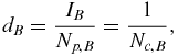 $$\begin{equation}
{d_B} = \frac{{{I_B}}}{{{N_{p,B}}}} = \frac{1}{{{N_{c,B}}}},
\end{equation}$$
$$\begin{equation}
{d_B} = \frac{{{I_B}}}{{{N_{p,B}}}} = \frac{1}{{{N_{c,B}}}},
\end{equation}$$
where IB is the flight strength, Np,B and Nc,B are the fatigue life limit and calendar life limit of point B, respectively. The Np,B and Nc,B can be calculated using the following equation:
 $$\begin{equation}
{N_{P,B}} = {I_B} \times {N_{c,B}} = C({N_{c,B}}) \times {N_p},
\end{equation}$$
$$\begin{equation}
{N_{P,B}} = {I_B} \times {N_{c,B}} = C({N_{c,B}}) \times {N_p},
\end{equation}$$
where Np is the fatigue safe life, and C(Nc,B ) can be determined by Equation (2).
Step 3: Prediction of structural residual life
If an aircraft is only grounded in a typical environment, the residual life of the aircraft structure can be predicated using the ASLE corresponding to its service conditions. For example, the service conditions of an aircraft are shown in Table 1.

Figure 5. Schematic diagram of the residual life prediction using the ASLE.
Table 1 Service conditions of an aircraft

According to Equations (3) and (4), the cumulative damage of the aircraft structure (dC ) can therefore be calculated as follows:
 $$\begin{equation}
{d_C} = \frac{{{I_1} \cdot {T_1} + {I_2} \cdot {T_2}}}{{{N_p}}} + \frac{{{I_3} \cdot {T_3}}}{{{N_{p,3}}}} + \frac{{{I_4} \cdot {T_4}}}{{{N_{p,4}}}}
\end{equation}$$
$$\begin{equation}
{d_C} = \frac{{{I_1} \cdot {T_1} + {I_2} \cdot {T_2}}}{{{N_p}}} + \frac{{{I_3} \cdot {T_3}}}{{{N_{p,3}}}} + \frac{{{I_4} \cdot {T_4}}}{{{N_{p,4}}}}
\end{equation}$$
In Equation (6), Np is the fatigue safe life under the baseline load spectrum; and N p,3 and N p,4, the limits of fatigue safe life under these flight strength, can be calculated using Equation (5). The residual damage of the structure (dR ) is
 $$\begin{equation}
{d_R} = 1 - {d_C}
\end{equation}$$
$$\begin{equation}
{d_R} = 1 - {d_C}
\end{equation}$$
If the aircraft will service in a flight strength I 5 until its retirement, the residual fatigue life (Np,R ) is
 $$\begin{equation}
{N_{p,R}} = {d_R} \times {N_{p,5}},
\end{equation}$$
$$\begin{equation}
{N_{p,R}} = {d_R} \times {N_{p,5}},
\end{equation}$$
where N p,5 is the limit of fatigue safe life under the flight strength I 5, it can be calculated using Equation (5). The residual calendar life (Nc,R ) is
 $$\begin{equation}
{N_{c,R}} = {N_{p,R}}/{I_5}
\end{equation}$$
$$\begin{equation}
{N_{c,R}} = {N_{p,R}}/{I_5}
\end{equation}$$
The previous steps show the life prediction method for an aircraft grounded in one type of environment. In reality, an aircraft is usually used in different regions and grounded in different environments to fulfil its tasks. In the life prediction process for several environments based on the ASLE, different ASLEs for these environments should be used (i.e., Fig. 4). The damage quantity is still the bridge between the consumed life and residual life. First, the effective period of the protective coating can be determined by converting the damage quantity of the protective coating under different environments. Second, the damage quantity of the structure in the effective period of the protective coating can be calculated. Third, the damage quantities under different environments after the protective coating losing its integrity can be calculated using the ASLEs, respectively. Finally, the consumed damage can be obtained and the residual life can be predicted according to the flight plan based on the ASLEs.
4.2 Service life extension of aircraft structures
Many older aircraft are facing aging issues and reaching their life limits. If there are no newer aircraft to replace the older ones, or there have been economic problems and so on, the users (e.g., the Air Force) typically will keep the old aircraft in service to meet their needs, so the service life of the aircraft is extended.
The service life extension of an aircraft structure is actually the extension of its life limits. It is the scope of the extension of the ASLE reflected in the diagram. If the scope of the ASLE has been extended, the baseline to calculate the damage quantity will be enlarged. The structural cumulative damage, which reaches 1 based on the former ASLE, will be less than 1 based on the extended ASLE. The structure can continue to be used until its cumulative damage reaches 1 based on the extended ASLE. There are two approaches to extend the ASLE: scope extension based on reliability analysis after the aircraft reaches its structural life limit, and scope extension based on structural repair in service period.
4.2.1 Scope extension of the ASLE based on reliability analysis
The ASLE is a safe and reliable life scope for aircraft structures in service. If the fatigue lives of a type of aircraft follow the log-normal distribution, the ASLE must have a reliability of 0.999 and a confidence level of 0.9(35). That is to say, for a fleet of 1,000 aircraft, there will have to be about one aircraft that fails and cannot be further used when all aircraft in the fleet reach their life limits. If the failed aircraft are removed through inspection and the remaining aircraft are set as a new fleet, the new fleet can be further used with a reliability of 0.999 and a confidence level of 0.9 through a newer reliability analysis.
On the basis of the reliability analysis, the scope of ASLE can be extended by the following steps. The schematic diagram of the scope extension of the ASLE based on reliability analysis is shown in Fig. 6.

Figure 6. Schematic diagram of the scope extension of the ASLE based on reliability analysis.
Step 1: Removing the failed aircraft through inspection
For a given type of aircraft, when all aircraft reach their structural life limits and their service lives need to be extended for further service, a structural inspection process should be carried out first to assess the structural state. The purpose of this process is to evaluate whether it is more economical to perform a service life extension program or to retire the aircraft. Through a teardown inspection and evaluation, if the critical components of an aircraft have been damaged too severely to extend the service life economically, the aircraft should be retired.
Step 2: Setting the remaining aircraft as a new fleet, and establish a newer ASLE
The remaining aircraft still have fatigue life until fracture. If we set them as a new fleet to carry out newer fatigue tests and reliability analysis, they can be further used with a reliability of 0.999 and a confidence level of 0.9. A newer ASLE can be established as the curve Tp–A 2–N p2–A 2’–N c2 shown in Fig. 6.
During the service period of aircraft structures, the effective period of the protective coating is independent from the extension of the structures, which means the effective period of the protective coating is unchanged in the newer ASLE. Moreover, some simulated specimens that have undergone the equivalent accelerated fatigue and corrosion process of actual structures should be further tested to obtain the fatigue safe life (N p2) and the C(T)2 curve in the newer ASLE. After the newer ASLE has been established, a full-scale fatigue test is recommended to verify the safety of service life extension. Typically, the aircraft that has been used the most heavily is selected as the test article.
In reality, if the former flight experience of an aircraft whose service life has been extended is left out of the account, the newer ASLE can be used solely to manage the service life of the aircraft.
Step 3: Extending the scope of the former ASLE
The newer ASLE Tp–A 2 –Np2 –A 2 ’–Nc2 is actually a safe and reliable life scope for the aircraft whose service life has been extended. It is also the extendable scope for the former ASLE Tp–A–Np–Aʹ–Nc in Fig. 6. The extended ASLE Tp1 –A 1 –Np1 –A 1 ’–Nc1 can be obtained by extending the scale of the former ASLE Tp–A–Np–Aʹ–Nc with the newer ASLE Tp–A 2 –Np2 –A 2 ’–Nc2 . As shown in Fig. 6, the abscissa value and ordinate value of any point B 1 on the extended ASLE are the summations of those of the B point on the former ASLE and the B 2 point on the newer ASLE, respectively. The B, B 1 and B 2 points are located on the same line that goes through the origin point, and they correspond to the same flight strength of the aircraft. Using the extended ASLE to manage an aircraft's structural life, all the flight experiences should be accounted for since the aircraft started service.
4.2.2 Scope extension of the ASLE based on structural repair
The structural statement can be improved through maintenance (inspection, repair or replacement of the critical components) which can extend the service life of the aircraft(Reference Sahay36). In the diagram of the ASLE, the structural maintenance process extends the scope of the ASLE.
Through repetitive repair and replacement of the components, the service life of an aircraft can be extended continuously, which means the ASLE can also be extended continuously. In reality, the structure of an aircraft has an economic life. The economic life is the period during which it is more cost-effective to maintain and repair an aircraft than to replace it. Consequently, the structural maintenance time is limited. Only three types of economic maintenances are discussed in this paper.
Type 1: The protective coating has been repaired before it loses integrity
If the protective coating has been repaired before it loses integrity, the structures can be considered to be suffering from pure fatigue damage before the repaired protective coating loses integrity. The left part of the ASLE is extended as shown in Fig. 7(a).

Figure 7. Scope extension of the ASLE based on structural repair. (a) The protective coating has been repaired before it loses integrity, (b) The protective coating is repaired after it loses integrity for a long time, (c) Thorough repairs or replacement of the critical components are carried out.
Type 2: The protective coating is repaired after it loses integrity for a period of time
If the protective coating is repaired after it loses integrity for a period of time, the structures will experience a pure fatigue state after service in the corrosion fatigue condition for the period of time. Part of the right part of the ASLE will be extended as shown in Fig. 7(b).
Type 3: Thorough repairs or replacement of the critical components are carried out
If the damaged structures are repaired or replaced by new ones, the state of the damaged structures will be improved. The baseline service life of the aircraft will be extended, and all of the ASLEs will be extended as shown in Fig. 7(c).
In practical applications, the former approaches can be used together to extend the scope of the ASLE and to extend the service life of an aircraft.
5.0 APPLICATION EXAMPLE
This section takes the skin of a type aircraft as an example to establish the ASLE of a given structure as well as its residual life prediction process. The ASLE of the aircraft is usually determined comprehensively by the ASLEs of the critical components. This example is just the most basic and the simplest application of the ASLE. The following processes can also be applied to other aircraft structures.
5.1 Material and methods
Much research has been devoted to the failure laws of different types of protective coatings through corrosion tests in reference(Reference Li, Liu and Yang37). According to the test results, the effective period of the protective coating is around 10 years, so only unprotected specimens have been tested to establish the ASLE in this paper.
Unprotected specimens are made from an aluminium alloy 2A12-T4 (AA 2A12-T4) plate with aluminium cladding. The AA 2A12-T4, which has almost the same chemical composition, mechanical performance and corrosion resistance as the aluminium alloy 2024-T4, is extensively used as a structural material in the aviation industry in China due to its light weight and high strength. The chemical composition of the AA 2A12-T4 is (in weight %): Cu 4.62, Mg 1.60, Mn 0.54, Fe 0.22, Si 0.10, and Al (balance). The tensile and yield strengths of AA 2A12-T4 are 296 MPa and 430 MPa, respectively.
To study the life degeneration laws of the skin of an aircraft, all the specimens were pre-corroded on one side. The geometry and pre-corrosion area of the specimens are shown in Fig. 8. The pre-corrosion area was exposed to a salt mist environment while the other area was wrapped by olefin.
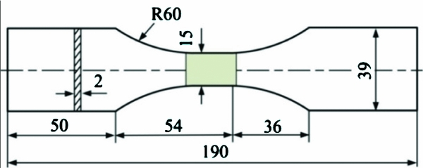
Figure 8. Geometry and pre-corrosion area of specimen (mm).
The solution used for the corrosion investigations was 0.6 M NaCl + 5 × 10⁻⁵ M H2SO4 (pH = 4) prepared from reagent-grade chemicals and distilled water. The pre-corrosion process was performed in a YWX/Q-250 corrosion box, which keeps temperature at 40±2℃ and deposits salt spray at 2mL/(h × 80 cm2). Sixty-five hours of pre-corrosion in the corrosion box is equivalent to approximately 1 year in a grounded environment for the aircraft(Reference Zhou38).
After being pre-corroded for 0, 325, 650, 1,300 and 1,950 hours, respectively (with equivalent corrosions for 0, 5, 10, 20 and 30 years in a service environment), fatigue tests were carried out using the MTS-810-500KN fatigue test system. All of the specimens were subjected to a constant amplitude load with a maximum tensile stress of 190 MPa and a stress ratio of 0.06 until fracture in an indoor environment. Forty cyclic loads of the load spectrum are equivalent to 1 hour of baseline flight for the aircraft.
Four available data in each pre-corrosion period were selected to calculate the fatigue safe lives and the C(T) curve. The test data are shown in Table 2.
Table 2 Test data of the pre-corrosion tests of unprotected specimens

5.2 Establishment of the ASLE
If the fatigue lives under accelerated corrosion test follow a log-normal distribution(Reference Nesterenko and Nesterenko8), the fatigue safe life with a reliability of 0.999 and a confidence level of 0.9 (Np and N 99.9(T)) is calculated by Equation (10):
 $$\begin{equation}
{N_{99.9}}(T) = {10^{{{\bar{X}}_T} - k \cdot {S_T}}}
\end{equation}$$
$$\begin{equation}
{N_{99.9}}(T) = {10^{{{\bar{X}}_T} - k \cdot {S_T}}}
\end{equation}$$
The pure fatigue safe life Np
is actually the N
99.9(0) value of structure without corrosion. In Equation (10),
 ${\bar{X}_T}$
is the logarithmic average of the equivalent fatigue life of the specimens corroded for equivalent T years, ST
is the logarithmic standard deviation of the equivalent fatigue life, and k is a lower confidence limit of reliability to insure the fatigue safe lives with a reliability of 0.999 and a confidence level of 0.9. Formulas for
${\bar{X}_T}$
is the logarithmic average of the equivalent fatigue life of the specimens corroded for equivalent T years, ST
is the logarithmic standard deviation of the equivalent fatigue life, and k is a lower confidence limit of reliability to insure the fatigue safe lives with a reliability of 0.999 and a confidence level of 0.9. Formulas for
 ${\bar{X}_T}$
and ST
are shown as Equations (11) and (12), respectively(Reference Gao4), and the value of k is 7.1293 when the sample number (n) is 4(Reference Fang, Wu, Sun, Yu, Ding, Zhou and Zhang39). Specifically,
${\bar{X}_T}$
and ST
are shown as Equations (11) and (12), respectively(Reference Gao4), and the value of k is 7.1293 when the sample number (n) is 4(Reference Fang, Wu, Sun, Yu, Ding, Zhou and Zhang39). Specifically,
 $$\begin{equation}
{\bar{X}_T} & =& \frac{1}{n} \cdot \sum\limits_{i = 1}^n {\log {N_i}(T)} ,\\
\end{equation}$$
$$\begin{equation}
{\bar{X}_T} & =& \frac{1}{n} \cdot \sum\limits_{i = 1}^n {\log {N_i}(T)} ,\\
\end{equation}$$
 $$\begin{equation}
{S_T} & =& \sqrt {\frac{1}{{n - 1}} \cdot \sum\limits_{i = 1}^n {{{(\log {N_i}(T) - {{\bar{X}}_T})}^2}} } ,
\end{equation}$$
$$\begin{equation}
{S_T} & =& \sqrt {\frac{1}{{n - 1}} \cdot \sum\limits_{i = 1}^n {{{(\log {N_i}(T) - {{\bar{X}}_T})}^2}} } ,
\end{equation}$$
According to the former three equations and Equation (1), the fatigue safe lives N 99.9(T) and the corrosion effect coefficients C(T) are calculated as in Table 3.
Table 3 Fatigue safe lives and corrosion effect coefficients of the unprotected specimens

According to Equation (2), the corrosion effect coefficient curve is fitted as Equation (13) with a correlation coefficient (R 2) of 0.999.
 $$\begin{equation}
C(T) = 1 - 0.139{T^{0.537}}
\end{equation}$$
$$\begin{equation}
C(T) = 1 - 0.139{T^{0.537}}
\end{equation}$$
Comprehensively considering corrosion laws of AA 2A12-T4, demands of static strength, fracture characteristics in corrosive environments and the demand of economical mending, the fatigue scatter factor will become too large due to the influence of the corrosion after the aircraft is in service for a long period if the aircraft services lighter than the flight strength of 50 baseline flight hours per year. Consequently, the boundary point Aʹ in the ASLE corresponds to the flight strength of 50 baseline flight hours per year, and can be determined by:
 $$\begin{equation}
{N_p} \cdot C({N_{c,A'}}) = 50 \cdot {N_{c,A'}}
\end{equation}$$
$$\begin{equation}
{N_p} \cdot C({N_{c,A'}}) = 50 \cdot {N_{c,A'}}
\end{equation}$$
The abscissa and ordinate values of point Aʹ are 24.1 years and 1,205 baseline flight hours, respectively.
The left part of the ASLE can be established through the effective period of the protective coating (10 years) and the pure fatigue safe life (5,150 fh). The right part of the ASLE can be established through the pure fatigue safe life (5,150fh), the corrosion effect coefficient curve (C(T) = 1 – 0.139T 0.537) and the boundary point Aʹ(24.1 years calendar life). The whole ASLE of the aircraft skin is shown in Fig. 9.

Figure 9. ASLE of the aircraft structure.
5.3 Residual life prediction of the aircraft structure
Based on the ASLE and according to Equations (3), (4), (5) and (13), the structural damage degrees corresponding to different states of protective coating and some flight strengths are listed in Table 4.
Table 4 Structural damage degrees corresponding to different flight strengths

Referring to flight records, the flight strength of an aircraft is 160 baseline flight hours per year in the first 6 years, 180 baseline flight hours per year for the next 7-12 years, and finally 120 baseline flight hours per year for 3 years. According to Equation (6), the cumulative damage of the skin is:
 $$\begin{equation}
{d_C} = \frac{{160 \times 6 + 180 \times 4}}{{5150}} + \frac{{180 \times 2}}{{2322}} + \frac{{120 \times 3}}{{1956}} = 0.6653
\end{equation}$$
$$\begin{equation}
{d_C} = \frac{{160 \times 6 + 180 \times 4}}{{5150}} + \frac{{180 \times 2}}{{2322}} + \frac{{120 \times 3}}{{1956}} = 0.6653
\end{equation}$$
According to Equation (7), the residual damage of the skin is 0.3347. If there are no repairs of the skin and the aircraft is in services for 100 baseline flight hours per year, the residual fatigue life and calendar life of the skin will be 599 baseline flight hours and 6 years, respectively, according to Equations (8) and (9).
6.0 CONCLUSIONS
ASLE is a safe and reliable scope of fatigue life and calendar life for aircraft structures in service. It can be used to manage aircraft structural life in varied service environments. On the basis of previous studies, this paper proposes the concept of the ASLE, specific steps to establish it, and how to predict the residual life of aircraft structure by using it. The corrosion effect coefficient curve is used to simulate the interactive processes of corrosion and fatigue on the aircraft structure in an actual service environment, and the Miner theory is used in the prediction process of the residual life. Moreover, a service life extension method for aircraft structures is proposed based on the scope extension of the ASLE, which includes methods based on reliability analysis and structural repair. Finally, taking the skin of a type of aircraft as an example, the establishment and application processes of the ASLE are presented.
The establishment of ASLE will pave the way for supervision of the structural life for individual aircraft. Besides the residual life prediction and the service life extension, the ASLE also has many other applications such as tracking of individual aircraft, determination of maintenance times, control of flight plans and so on. Further studies are still needed to promote the development of the ASLE.
Acknowledgements
Financial support for this study was granted by National Natural Science Foundation of China (51475470).


