NOMENCLATURE
- A
propeller disk area
- Ae
duct exit area
- AoA
duct angle-of-attack
 $c_{duct}$
duct profile chord length
- $D_{in}$
duct inner diameter
- FoM
figure of Merit
- Ma
mach number
- $P_{df}$
ducted fan power
- $P_{op}$
open propeller power
- Re
Reynolds number (
$Re=V_\infty c_{duct}/\nu_\infty$)- RPM
revolutions per minute
- $T_{df}$
duct fan thrust
- $T_{op}$
open propeller thrust
- $V_\infty$
free-stream speed
- $V_{tip}$
blade tip speed
- $\beta$
blade pitch angle at 70% radial section
- $\Lambda$
expansion ratio,
$\Lambda = A_e/A$- $\mu$
propeller advance ratio (
$\mu = V_\infty / n D$)- $\nu_\infty$
free-stream kinematic viscosity
- $\rho_\infty$
free-stream density
- CFD
computational fluid dynamics
- DDES
delayed detached Eddy simulation
- eVTOL
electric vertical take-off and landing
- MAV
micro aerial vehicle
- PAV
personal aerial vehicle
- PIV
particle image velocimetry
- UAV
unmanned aerial vehicle
- URANS
unsteady Reynolds averaged Navier–Stokes


1 INTRODUCTION
The ducted fan, or ducted/shrouded propeller concept, was first examined experimentally by Stipa(Reference Stipa1) in the 1930s, and soon after it was widely studied using theory and further experiments. An overview of most early studies, before 1962, was presented by Sacks and Burnell.(Reference Sacks and Burnell2) Reviews on more recent studies can be found in the dissertations of Pereira,(Reference Pereira3) and of Akturk and Camci,(Reference Akturk and Camci4) although emphasis was put on UAV (Unmanned Aerial Vehicle) applications. A clear resurgence in ducted fan research in recent years can be noticed, due to the growing interest in UAV/MAV (Micro Aerial Vehicle), PAV (Personal Aerial Vehicle), and electric propulsion.
The ducted fan is a propeller inside a circular duct. It can be considered as a hybrid of a propeller and a turbofan engine, while the turbofan can be seen as a ducted fan driven by a turbojet. The duct is usually considered as an annular wing.(Reference Fletcher5) The duct brings superior static performance over its free propeller counterpart given the same power, as confirmed by many early-age experiments.(Reference Krüger6–Reference Grunwald and Goodson8) The performance gains are mainly attributed to the combined effect of suction on the curved duct inlet lip and the larger static pressure around the diffuser outlet.
A simple analysis for ideal hover cases can be made using momentum theory. For the same thrust required, the power reduction  $P_{df}/P_{op}$ can be written as a function of the expansion ratio
  $\Lambda$:
 \begin{equation}\frac{P_{df}}{P_{op}}= \frac{1}{\sqrt{2\Lambda}},\end{equation}
where df stands for ducted fan and op for open propeller.
Given the same power, the thrust improvement  $T_{df}/T_{op}$ can also be defined as a function of the expansion ratio
  $\Lambda$:
 \begin{equation}\frac{T_{df}}{T_{op}}= \sqrt[3]{2\Lambda}.\end{equation}
It can thus be seen that performance improvements can be achieved, as long as  $\Lambda$ is kept greater than
  $0.5$. The higher the expansion ratio
  $\Lambda$, the higher the performance improvement. More detailed analyses using momentum theory can be found in Ref. [Reference Pereira3]. In reality, the expansion ratio
  $\Lambda$ is restricted by the adverse pressure gradient, which may lead to flow separation inside the diffuser.
Apart from UAV applications, the ducted fan can be an ideal choice for novel rotorcraft configurations. For instance, when installed on a compound helicopter, as auxiliary propulsion, higher propulsion efficiency than traditional propellers can be expected. Though the duct may create more blockage to the rotor wake, it protects the propeller from excessive propeller/rotor aerodynamic interactions. If mounted at the wing tip, to form a tilt-ducted-fan configuration such as the Doak VZ-4, the ducted fan produces less wing downwash. The duct also provides protection to the propeller, and to ground personnel/equipment. Especially in emergencies, the duct can support containment, preventing further damage to the airframe. Further, by adding guide vanes at the outlet to deflect the airflow, the ducted fan is able to provide vectored thrust either for sideways propulsion or control purposes, hence, in several cases, the need for tail rotor and empennage can be eliminated, as in the Piasecki 16H-1A (see Fig. 1(a)). A future ducted fan could be made into a compact, electricity-driven, removable, plug-in, propulsion unit, by integrating the control and power inside the shroud and introducing contra-rotating fans to eliminate the overall torque. This approach to design is important for the standardisation and modularisation of propulsion units for future novel rotorcraft configurations.

Figure 1. Ducted fan compound helicopter applications. (a) Piasecki 16H-1A. (b) Piasecki X-49A SpeedHawk. (c) VFW H3 Sprinter. (d) Coaxial Compound Helicopter (CCH) by Johnson et al.(Reference Johnson, Elmore, Keen, Gallaher and Nunez13)
Indeed, a ducted fan can be made into an UAV if adequate, controlled, outlet vanes are added. Applications in propulsors for hovercraft, fan-in-wing configurations, or tail-rotor, as the fan-in-fin design for helicopters can also be found. Applications to marine propulsion,(Reference Carlton9) and wind turbines(Reference Gilbert, Oman and Foreman10,Reference Ohya, Karasudani, Sakurai, Abe and Inoue11) have also been reported. Nevertheless, few compound helicopters have adopted ducted fans for propulsion, e.g. the Piasecki 16H-1A (Fig. 1(a)) and X-49A (Fig. 1(b)), and the VFW H3 Sprinter (Fig. 1(c)). In Johnson’s conceptual design for urban compound helicopters,(Reference Gaffey, Zhang, Quackenbush, Sheng and Hasbun12,Reference Johnson, Elmore, Keen, Gallaher and Nunez13) ducted fans were chosen for efficiency and safety reasons, and were mounted on wings near the tail, under the rotor (Fig. 1(d)). However, very few performance analyses of the ducted fans in these configurations can be found in the open literature. More applications of ducted fans are presented in Fig. 2(a)-(g), such as on the Bell X-22A aircraft (Fig. 2(a)) and the Doak VZ-4 (Fig. 2(c)). More recent applications are shown in Fig. 3(a)-(e), such as on the Hybrid Air Vehicle (Fig. 3(b)) and the Airbus E-fan (Fig. 3(d)). The recently unveiled Bell Nexus air taxi, as shown in Fig. 3(e), features six tiltable ducted fans for lift and thrust. However, it should be noted that most of these aircraft were prototypes and did not enter production, or service.
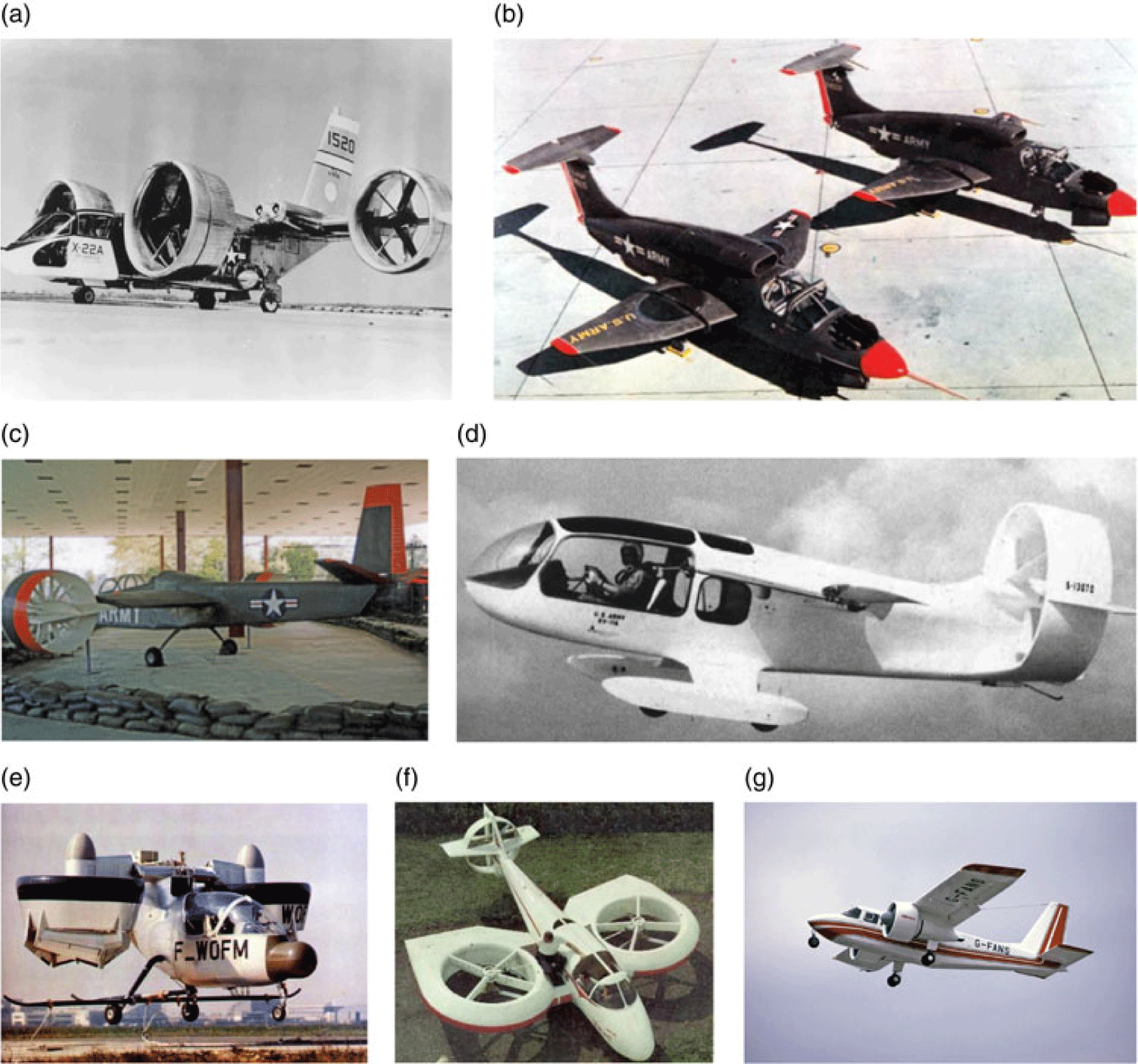
Figure 2. Ducted fan aeronautical implementations (20th century). (a) Bell X-22A. (b) Ryan XV-5. (c) Doak VZ-4. (d) XV 11A Marvel. (e) Nord 500 Cadet. (f) Vanguard Omniplane. (g) Britten-Norman BN-2 Islander.

Figure 3. Ducted fan aeronautical implementations (21 st century). (a) UrbanAero AirMule. (b) Hybrid Air Vehicle. (c) Parker Alienair 1. (d) Airbus E-fan. (e) Bell Nexus.
The disadvantages of a ducted fan, in comparison to an open propeller, apart from the salient weight and drag penalty due to the shroud, include poor performance at very high duct angles of attack, inflow distortion and possible stall on the upstream inner duct side. This can possibly be triggered by high-rate descending or working under substantial downwash flow. Aerodynamic forces and moments imposed on the duct may also be problematic. However, the aforementioned benefits may still give the ducted fan a chance to compensate for its deficiencies. Treatments and optimisation to mitigate the deficiencies should be further investigated and evaluated in future ducted fan research.
2 EXPERIMENTAL WORKS ON DUCTED FANS
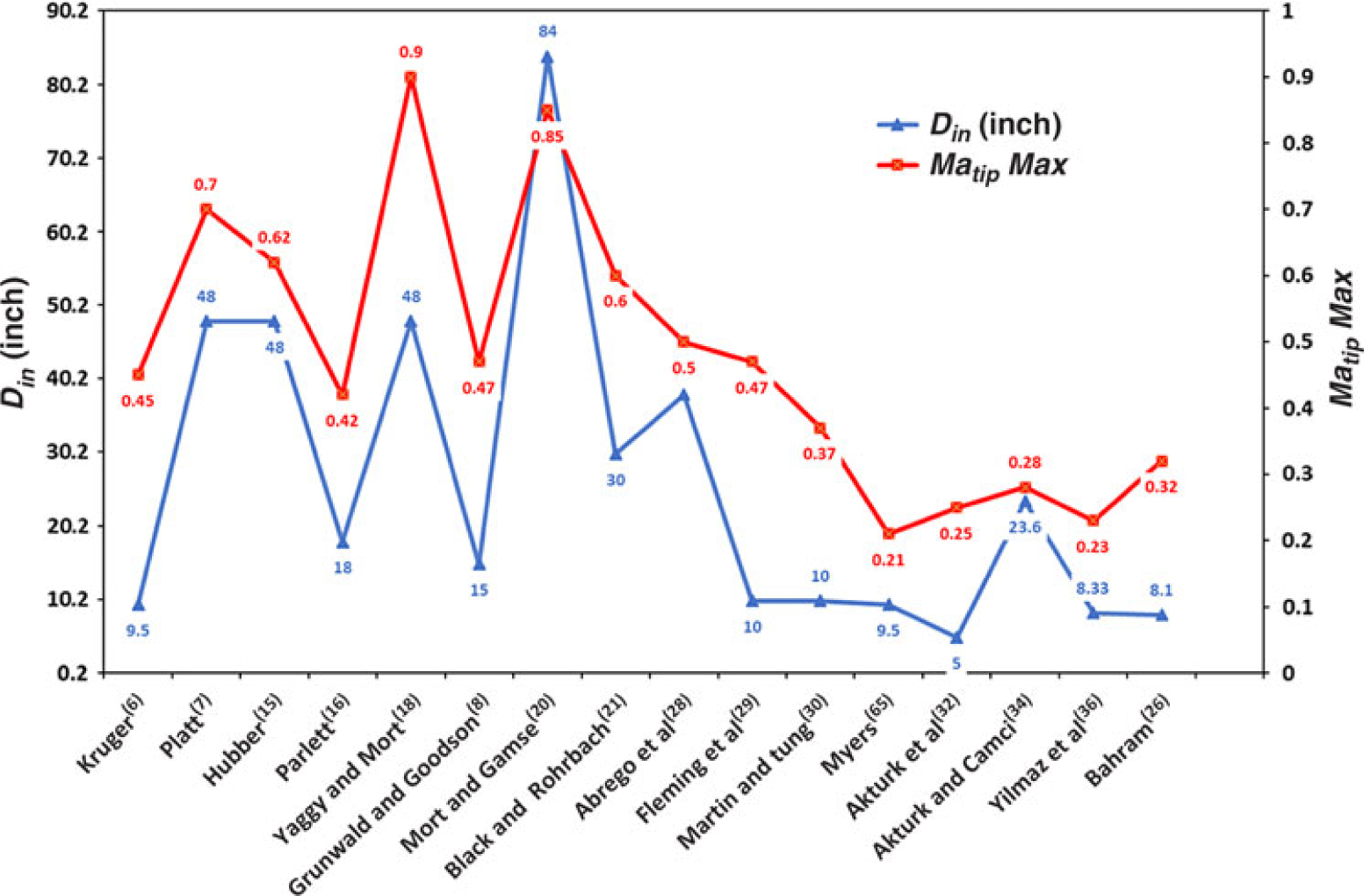
As summarised by Sacks and Burnell,(Reference Sacks and Burnell2) Pereira(Reference Pereira3) and Akturk and Camci,(Reference Akturk and Camci4) plenty of experimental and theoretical studies on ducted fan aerodynamics can be found. Recent experimental studies mostly focused on UAV/MAV applications. Therefore, as shown in Figs 4 and 5, the scale, compressibility, and Reynolds number (based on free-stream speed and duct chord length) of recent studies are only comparable to small, model-sized experiments from years ago. As suggested by Goodson and Grunwald,(Reference Goodson and Grunwald14) model-sized tests can be used to approximate full-scale performance, provided that the duct lip separation effects are avoided. However, lip separation is more likely to take place in model-sized tests due to the low Reynolds number. Table 1 presents a summary of the experiments, including the model scales and geometries, estimated maximum tip Mach number, and main objective of each study. These experiments are discussed in detail in this section, with emphasis put on studies featuring large duct sizes, high Reynolds numbers, and well-documented setups.

Figure 4. Scale (denoted by duct inner diameter  $D_{in}$ in inch) and compressibility (denoted by maximum blade tip Mach number
  $Ma_{tip}{Max}$) comparisons of ducted fan experiments.

Figure 5. Maximum Reynolds number comparisons of ducted fan experiments (based on  $V_\infty$ and
  $c_{duct}$).
Table 1 Experiments on ducted fans
A: Acquirable, NA: Not Acquirable. img: geometry provided by images. –: not included. nbs: no blade sections available
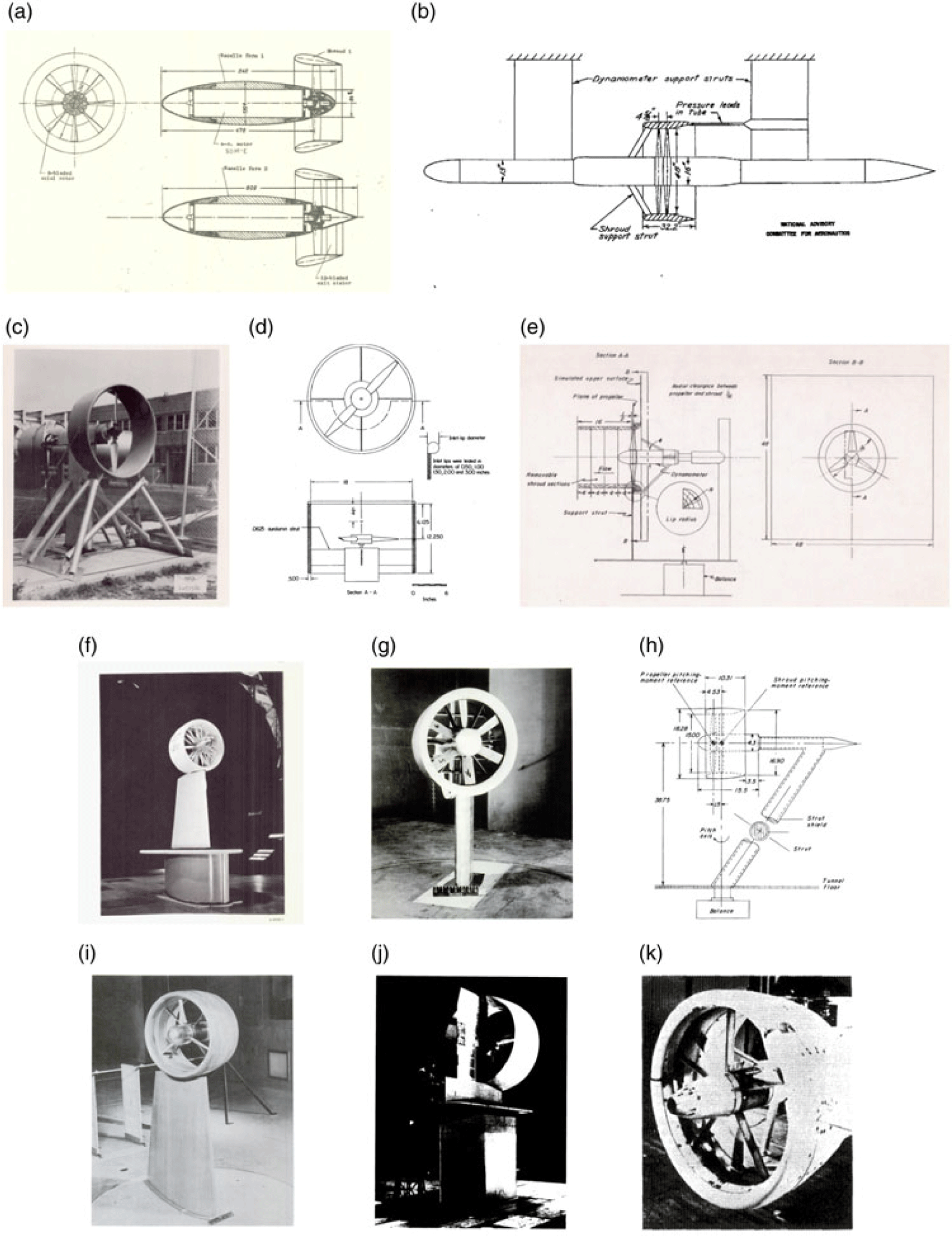
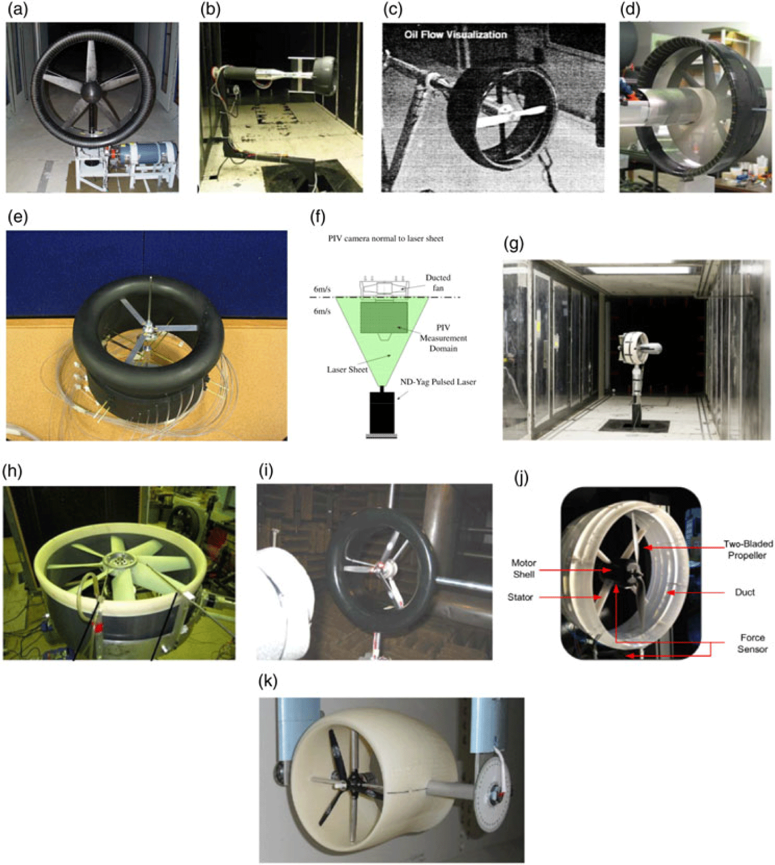
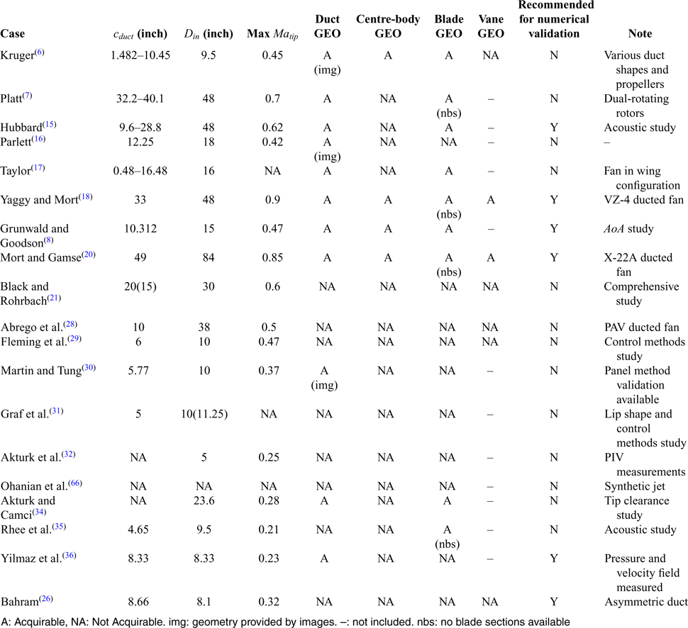
Figure 6. Early experiments on ducted fans. (a) Krüger.(Reference Krüger6) (b) Platt.(Reference Platt7) (c) Hubbard.(Reference Hubbard15) (d) Parlett.(Reference Parlett16) (e) Taylor.(Reference Taylor17) (f) Yaggy and Mort.(Reference Yaggy and Mort18) (g) Grunwald and Goodson.(Reference Grunwald and Goodson19) (h) Grunwald and Goodson.(Reference Grunwald and Goodson8) (i) Goodson and Grunwald.(Reference Goodson and Grunwald14) (j) Mort and Gamse.(Reference Mort and Gamse20) (k) Black and Rohrbach.(Reference Black and Rohrbach21)
2.1 Early experiments on ducted fans
Selected early experiments are listed in Fig. 6(a)-(k). Very early experiments before the 1960s (Fig. 6(a)-(e)) are summarised briefly in Table 1 due to lack of detailed information in the corresponding references. Nevertheless, results and conclusions of these tests are discussed in the summary of research challenges (Section 4). This section focuses mostly on the full-scale wind tunnel test campaign performed by NASA (Fig. 6(f)-(j)) during the development of two VTOL aircraft, the Doak VZ-4DA and the Bell X-22A, which utilised ducted fans for propulsion and lift. The experiments focused on examining the aerodynamic performance of the specific designs. Test matrices of these experiments are presented in Tables 2–4.
The 4-foot-diameter ducted fan of the Doak VZ-4DA tilt-duct VTOL airplane was tested while mounted at the tip of a semi-span wing representing a real-world design (Fig. 6(f)). Experiments were systematically conducted and documented(Reference Yaggy and Mort18,Reference Mort and Yaggy22–Reference Yaggy and Goodson24) to investigate the performance of this specific shape. It is noted that geometric information of the entire wing/ducted-fan combination was presented in detail, except for the blade sections. The configuration had a complex structure, as the propeller was eight-bladed. A nine-bladed stator was installed to support the centre-body. Either 7 or 14 guide vanes were installed at the duct inlet, and a small tapered wing with a 25% plain flap was placed at the exit as a guide vane.
The experiments accounted for comprehensive variations including free-stream speed, AoA of the wing, the ducted fan’s relative angle to the wing, advance ratio, blade pitch angle, power input etc. Power, forces and moments of the ducted fan and wing combination, stall boundary for the upstream lip (through tuft flow visualisation), and surface pressure were measured. To support future use of the ducted fan for control purposes, the effectiveness of various means, i.e. inlet vanes to alter the effective pitch angle of the blades, direct change of the blade pitch, and exit vanes to deflect the air, were evaluated. The exit vane was eventually concluded as the most effective method. In these full-scale tests, the maximum Reynolds number based on the free-stream speed and the duct chord length was between 4 and 7m. The experiments, however, did not provide comprehensive measurements of the isolated ducted fan (though the isolated wing’s performance was measured), as the duct had to be mounted at the wing-tip.
Table 2 Test matrix for the 7-foot ducted fan by Mort and Gamse(Reference Mort and Gamse20)

Table 3 Test matrix for the 4-foot ducted-fan/wing combination by Yaggy and Mort(Reference Yaggy and Mort18)

Table 4 Test matrix for the 5/16 model-sized ducted fan by Grunwald and Goodson(Reference Grunwald and Goodson8)

Grunwald and Goodson(Reference Goodson and Grunwald14,Reference Grunwald and Goodson19) also tested two model-sized wing/ducted-fan combinations (Fig. 6(g) and (i)), to investigate the aerodynamic characteristics in hover and transition modes. It was found that the ducted propeller carries a substantial proportion of forces during hovering and transition modes, and causes a large nose-up moment at low speed. With the exit guide vanes, the forces and moments could be trimmed, effectively. However, due to the small scale of the models and the resulting low Reynolds numbers (around 0.5m), flow separation at the duct lip, which at full-scale may not be present, could not be avoided. Both experiments documented the geometry and the test conditions, but the propeller blade sections were not mentioned. However, it should be noted that, though not stated explicitly in the documents, the same ducted fan model was apparently used for the wing/ducted-fan combination study(Reference Goodson and Grunwald14) and to study cross-wind effects(Reference Grunwald and Goodson8) (Fig. 6(h)), and the blade sections are reported in Ref. [Reference Grunwald and Goodson8]
Later, a Bell X-22A ducted fan was examined by Mort and Gamse(Reference Mort and Gamse20) in the NASA Ames 40- by 80-foot wind tunnel during the aircraft development (Fig. 6(j)). Along with the aforementioned 4-foot experiments, the test was summarised by Kriebel and Mendenhall.(Reference Kriebel and Mendenhall25) Theoretical models were then built and examined. The models could predict well the ducted fan performance, yet differences could not be avoided due to the unevenly distributed disk loading and flow separation, showing the need for high-fidelity analyses.
Geometric definitions of the duct and the vanes were presented as well, but the blade profile was not documented. The structure of the 7-foot-diameter ducted propeller was slightly simpler than the 4-foot one of Ref. [Reference Yaggy and Mort18]. The duct was 49 inches in length, and had six unevenly distributed stator blades to support the centre-body. A three-bladed propeller was employed. A guide vane, similar to a small wing of rectangular planform, was installed at the flow exit to deflect the exhaust. Aerodynamic forces, power, and moments of the isolated ducted fan were measured, excluding the contributions from the wind tunnel support structure and fairing. Free-stream dynamic pressure, blade pitch angle, rotor RPM, AoA of the duct, and the exit vane deflection angle were set as the variables. The maximum Reynolds number based on the length of the duct was around 13m. However, only dimensionless parameters for the test conditions were documented, making the determination of the specific conditions difficult. Pressure distributions inside and outside the duct surfaces were also provided. The experiments confirmed the high performance of the specific design, and concluded that better high-speed performance could be achieved with design modifications. Pressure distribution measurements were included to identify stall at inlet and outlet. The geometry and stall boundary of the 7-foot duct were similar to those of the 4-foot duct.(Reference Yaggy and Mort18,Reference Mort and Yaggy22–Reference Yaggy and Goodson24) It was also found that upstream lip stall could easily happen at low power and high duct angle conditions, but stall at the downstream lip was not likely. Initially, the separation was local, and no large changes in performance were observed. As the cross-wind angle increased, flow separation occupied the entire duct lip and large changes in aerodynamic loads were noticed. The authors claimed that there is a critical lip radius above which the flow separation would be delayed and vice versa. In general, it can be argued that the duct lip separation depends on the difference between the fan power and the free-stream speed, the cross-wind angle, and the inlet lip geometry.
Experimental, and theoretical studies on more general configurations were also conducted. Black and Rohrbach(Reference Black and Rohrbach21) systematically investigated the performance of a 3-foot ducted fan, considering geometric variations of expansion ratio, inlet lip shape, external duct shape, propeller location, inlet/outlet vanes, blade shape, blade number, tip speed, and tip clearance (Fig. 6(k)). The Mach number varied from  $0.2$ to
  $0.6$ and comparisons were made against open propeller counterparts, with contributions from the duct and the propeller measured separately. Cross-wind effects were not included, but this research represents a comprehensive experimental investigation into the dominant factors of the ducted-fan static performance. The expansion ratio was identified as the most critical factor, which was consistent with theoretical analyses. A larger expansion ratio would be more beneficial to the static performance, but the cruise performance might be compromised. The authors recommended either specific shape optimisation or deformable shapes, as a way forward.
To study cross-wind effects, Grunwald and Goodson(Reference Grunwald and Goodson8) conducted experiments on a 15-inch diameter ducted fan, representing a 5/16 model of the aforementioned 4-foot ducted fan (Fig. 6(h)), considering duct AoA ranging from  $-10^{\circ}$ to
  $110^{\circ}$. No inlet nor outlet guide vanes were installed. The maximum Reynolds number, based on the tunnel wind speed and the duct length, was around 0.5m, corresponding to forward flight transition conditions of a tilt-duct VTOL aircraft. Shroud lip separation was identified as the angle-of-attack increased. The experiments also uncovered that the propeller contributions to the overall forces and moments were relatively small, highlighting the importance of the duct. Also, at different advance ratios, as long as separation appeared, the ratio of the propeller thrust to the total thrust grew rapidly. This ratio, however, decreased with the duct AoA when stall was eliminated, suggesting that stall has a detrimental effect on the duct’s performance. It is interesting that a modified lip geometry was proposed to resolve lip stall, and was shown to be effective. This suggests that an asymmetric duct design may be necessary, as also investigated by Bahram.(Reference Bahram26) However, it should be pointed out that the stall boundary specified by this model-sized experiment is narrower than the full-scale experiments. The scale of the duct plays an important role in the stall characteristics. As concluded by Mort,(Reference Mort23) for ducted fans that are big enough, e.g. those utilised by the X-22A and the VZ-4, inlet lip stall can only be encountered at very high rates of descent. The reports provided detailed geometric information about the blade and the duct, hence numerical validation can be made. In particular, Xu et al.(Reference Xu, Xing and Ye27) simulated the experiment at the AoA of
  $50^{\circ}$ using RANS. The stall on the upstream side was predicted and visualised, then a modified lip shape was added to eliminate the stall. Very limited data comparisons were made; nonetheless good agreement was achieved.
2.2 Recent experimental studies
A resurgence of ducted fan research in industry started in the 2000s because of the growth of interest in UAVs, PAVs, and electric propulsion. The models used in more recent experiments are presented in Fig. 7(a)-(k). Recent efforts feature a combination of modern experimental technologies and CFD simulations. However, it is noted that the scale of the models examined, and the resulting Reynolds numbers and compressibility were hardly comparable to experiments from the 1960s, as the recent research targeted mostly small-scale UAVs (such as in Fig. 7(b), (e), (g) and (i)). These studies often utilised very high RPM rotors (typically more than 8,000 RPM) at low Reynolds number ( $10^4$–
 $10^5$). Such combinations do not represent high-speed flight conditions, and can hardly be applied to large aircraft. Nevertheless, the tests are briefly summarised in Table 1, and some are further discussed in Section 4. Few experiments utilised large-scale models and/or presented inspiring results for aircraft applications, and these are summarised in detail.

Figure 7. Recent experiments on ducted fans. (a) Abrego et al.(Reference Abrego, Bulaga and Rutkowski28) (b) Fleming et al.(Reference Fleming, Jones, Ng, Gelhausen and Enns29) (c) Martin and Tung.(Reference Martin and Tung30) (d) Graf et al.(Reference Graf, Fleming and Ng31) (e) Pereira.(Reference Pereira3) (f) Akturk et al.(Reference Akturk, Shavalikul and Camci32) (g) Ohanian et al.(Reference Ohanian, Gelhausen and Inman33) (h) Akturk and Camci(Reference Akturk and Camci34) (i) Rhee et al.(Reference Rhee, Myers and McLaughlin35) (j) Yilmaz et al.(Reference Yilmaz, Erdem and Kavsaoglu36) (k) Bahram.(Reference Bahram26)
Abrego and Bulaga(Reference Abrego, Bulaga and Rutkowski28) investigated a ducted fan designed for PAVs. The ducted fan, as shown in Fig. 7(a), had a duct inner diameter of 38 inches and a 10-inch duct chord. A five-bladed propeller was installed. Two 3-inch exit guide vanes were used to vectorise the flow. The experiments accounted for various tunnel speeds, RPM, AoA, and vane deflection angles. The data and geometry were later adopted for CFD validation by Chang and Rajagopalan.(Reference Chang and Rajagopalan37) The simulated results matched the corrected experimental data, though the fan was represented by momentum sources. However, the detailed geometric information is not publicly available. Martin and Tung(Reference Martin and Tung30) examined a two-bladed, 10-inch ducted fan UAV (Fig. 7(c)), taking into account variations of the tunnel velocity, AoA, RPM, tip clearance, and duct leading edge radius. The performance of the ducted fan, as well as, of the isolated propeller, were measured. Stall boundaries of the isolated duct and the powered configuration were also identified. It was found that increasing the tip gap would severely compromise the overall performance. The experiments also reported that the flow appeared to separate after the rotor blade plane. The ducted fan model utilised in the tests was simple, and its purpose was to provide validation data for future modelling. However, the geometry of the duct and the blade, including the location of the propeller, are not explicitly defined in the paper. The experiments were later compared against panel method calculations by Lind et al.,(Reference Lind, Nathman and Gilchrist38) and good correlation within the attached flow region was achieved.
Akturk and Camci(Reference Akturk and Camci4,Reference Akturk and Camci34,Reference Camci and Akturk39–Reference Akturk and Camci41) and Akturk et al.(Reference Akturk, Shavalikul and Camci32) carried out numerical and experimental studies on ducted fan UAVs. They used PIV to measure the flow field outside a small ducted fan model(Reference Akturk, Shavalikul and Camci32,Reference Akturk and Camci40) (Fig. 7(f)), and the measurements agreed well with CFD simulations, where the rotor was represented by an actuator disk. The inlet flow distortion in conditions was revealed. However, due to the geometry of the duct, the flow field inside it, and near the blades could not be captured by the experiments. The free-stream speed was only 6m/s while the rotor RPM reached 9,000, which is typical for the ducted fan UAV studies as mentioned earlier. This is one of the few studies that first employed commercial codes and examined their applicability for ducted flow simulations. Later, Akturk and Camci also employed CFD methods in their double ducted fan(Reference Akturk and Camci4,Reference Camci and Akturk39) and tip clearance studies (Fig. 7(h))(Reference Akturk and Camci34,Reference Akturk and Camci41) .
More recently, Yilmaz et al.(Reference Yilmaz, Erdem and Kavsaoglu36) examined five different circular duct shapes using the same two-bladed propeller and a constant RPM (Fig. 7(j)). The duct sections were defined by several standard NACA airfoils or their combinations. The duct inner radius and the chord length were kept at 0.2117m, while the free-stream speed was up to 25m/s. The resulting Reynolds number based on the chord length was around half of Grunwald’s experiment. The blade geometry, however, was not described in detail. Performance of the open propeller was measured at different advance ratios for the purpose of further comparisons. The tests mainly explored effects of the advance ratio and the duct shape on the overall performance, and found that as the advance ratio grows, the thrust coefficient decreases and eventually becomes negative. A duct shape that has higher profile camber and higher expansion ratio was shown to provide better performance in the test. Also, the experiments showed that the propeller inside the duct performs poorer than the open propeller, but the overall performance of the ducted fan is better. Apart from force and power coefficients, the velocity profiles at the inlet and exit were measured and the results were presented. Pressure distributions along the duct inner surface were presented too. This case is suited for CFD validation despite the low Reynolds number, since the duct geometry is simple, the propeller can be represented by a matched model, and the available measurements are quite elaborate.
As most studies focused on the global shape, or the aft shape of the duct, Graf et al.(Reference Graf, Fleming and Ng31) specifically studied the inlet lip (Fig. 7(d)). The study pointed out that the lip shape defines the lip suction effect and alters the location of the pressure centre, which will further affect the pitching moments. Four different lip shapes were tested at static and cross-wind conditions. It is found that an increased lip radius is beneficial for static performance, due to its ability to maintain attached flow longer. However, the profile drag and the pitching behaviour brought by the lip shapes were detrimental. Compromise should therefore be made between the best static and best cross-wind performance. It is also interesting that the two symmetric shapes tested, showed poorer static performance, while shapes that generate a larger suction area in the inner surface were more favourable. Nonetheless, the experiments aimed at UAV applications, and the Reynolds number was low. Information on the model geometry and the detailed performance data was also restricted.
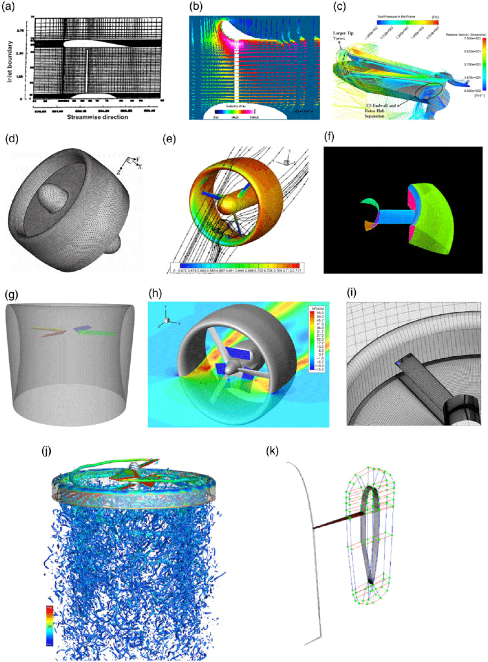
3 MODELLING DUCTED FANS
3.1 Theoretical and low-order methods
Theoretical studies on ducted fan performance using methods like the annular airfoil theory, lifting line, blade element or panel methods etc. can be found in the literature since many decades ago. Thwaites(Reference Thwaites42,Reference Thwaites43) presented detailed analyses for a fan inside a duct or tunnel based on strip theory, in the early 1950s. Kriebel and Mendenhall(Reference Kriebel and Mendenhall25) compared their theoretical analyses against experimental data, though in many cases, where heavy disk loadings and flow separation were encountered, only qualitative agreement could be achieved. Pereira(Reference Pereira3) also presented a detailed theoretical study. More recently, Bontempo and Manna(Reference Bontempo and Manna44) studied the exact solution of incompressible, axisymmetric and inviscid flow through the duct enclosing a non-uniform actuator disk. These methods can rapidly and quite accurately predict the performance in simple cases, and are suitable for fast analysis, of preliminary designs, for parametric studies.(Reference Bontempo and Manna45) However, in many cases, especially where flow separation is encountered, such models can only deliver results in qualitative agreement with test data.
Ahn and Lee(Reference Ahn and Lee49) proposed an axisymmetric analysis and design method for ducted fans, based on the extended stream-surface method by Ahn and Drela.(Reference Ahn and Drela50) Viscous effects were not included. The study investigated the diffuser angle and inlet lip radius, as well as it compared fan disk models, and tip loss models, but no validation was provided. The duct expansion angle was found to be the dominant factor, as also suggested by many previous studies. The inlet radius was shown to be less important. However, as evidenced by the experiments reported by Talylor,(Reference Taylor17) smaller lip radii may give rise to inflow separation at the lip. The computational resources required for the aforementioned analyses were very small. Later, an open source code called DFDC (Ducted Fan Design Code) by Youngren et al.(Reference Youngren, Drela and Sanders46) and Drela and Youngre(Reference Drela and Youngre51) was also reported (Fig. 8(a)). The code calculates rotor(s) using a lifting-line representation, blade element models, and vortex sheets, while the duct and centre-body are accounted for using axisymmetric panel methods. The code is capable of rapidly predicting the performance of ducted fans that have multiple rows of rotors and stators. It is also capable of quick design of ducted fans given certain performance requirements. DFDC can be found deployed in several analysis and design studies, but its accuracy is not widely validated. In addition, the code can only account for axial flight and steady conditions.
Figure 8. Lower-order simulations of ducted fan flow. (a) DFDC (Ducted Fan Design Code)(Reference Youngren, Drela and Sanders46) (blade elements, lifting line, panel methods). (b) Lind et al.(Reference Lind, Nathman and Gilchrist38) (blade elements, panel methods). (c) Bi et al.(Reference Bi, Kimmel and Haas47) (blade elements, panel methods). (d) AVID OAV(Reference Ko, Ohanian and Gelhausen48) (empirical data interpolation, actuator disks).
Lind et al.(Reference Lind, Nathman and Gilchrist38) adopted panel, as well as, blade element methods based on airfoil tables to model the Martin and Tung’s experiments(Reference Martin and Tung30) for a 10-inch-diameter ducted rotor. The potential flow method (Fig. 8(b)) predicted the forces well at high rotor RPM (9,000) and low free-stream speed, for AoA up to  $90^\circ$. However, the discrepancies in the pitching moment results were stronger. It is also noted that no lip separation occurred. At high free-stream speeds, only low AoA cases were compared. Nevertheless, the method required very low computational resources, and was seen as suitable for preliminary analyses. Bi et al.(Reference Bi, Kimmel and Haas47) investigated ducted fans designed as aerodynamic propulsors for shipboard applications using panel methods for the duct frame, and blade element methods for the propeller (Fig. 8(c)). The simulations, investigated the effect of variables including advance ratio, compressibility, blade twist, propeller location, and tip clearance. The study showed a decrease of the duct thrust contribution as the advance ratio increased. The inlet blockage was also investigated, and was found that it may induce significant vibration on the fixed and rotating parts of the structure. Validation was made against experiments, however, due to the proprietary nature of the model, quantitative comparisons were not publicly available.
The above mentioned methods can effectively and quickly calculate static performance, but can hardly account for flow separation and arbitrary flight conditions. Hence their usage is limited, and corrections from tests may be necessary. Nonetheless, Ko et al.(Reference Ko, Ohanian and Gelhausen48) presented a commercial code named AVID OAV (Fig. 8(d)), which integrates various strategies and multidisciplinary methods. To predict and optimise performance of ducted fan UAVs, methods like interpolations from empirical data for duct performance, actuator disks or blade vortex element representations of the rotor, empirical equations for control vane performance, etc. were considered. The predictions were in good agreement with wind tunnel and flight test data, and the code has been used for several ducted fan UAV designs such as the iStar.(Reference Guerrero, Londenberg, Gelhausen and Myklebust52) However, as mentioned above, the commercial code aimed at UAV applications, and little information is publicly available.
3.2 CFD simulations
The simulation of ducted fans, with blades and stators resolved, is within the capability of modern CFD methods and computers. Also, with the rapid development of commercial codes, many CFD simulations on UAV configurations were carried out in combination with practical tests. However, simulations of full-scale ducted fans for propulsion purposes at high Reynolds numbers are less common, and the same is true for ducted fans with stators or guide vanes. Simulation works are summarised here, as shown in Fig. 9(a)-(k), to show the advancements of CFD techniques, and suggest future development.

Figure 9. CFD simulations of ducted fan flow. (a) Rajagopalan and Zhang.(Reference Rajagopalan and Zhang53) (b) Chang and Rajagopalan.(Reference Chang and Rajagopalan37) (c) Akturk and Camci.(Reference Akturk and Camci34) (d) Ye et al.(Reference Ye, Ye and Qu54) (e) Xu et al.(Reference Xu, Xing and Ye27) (f) Sheng et al.(Reference Sheng, Zhao and Bi55) (g) Jimenez and Singh.(Reference Jimenez and Singh56) (h) Biava and Barakos.(Reference Biava and Barakos57) (i) Chen et al.(Reference Chen, Li, Huang and Xiang58) (j) Rubio et al.(Reference Rubio, Diaz and Yoon59) (k) Qing et al.(Reference Qing, Hu, Wang, Liu, Fu and Liu63)
In early attempts, actuator disk models for the propeller and incompressible Navier–Stokes simulations were considered. Rajagopalan and Zhang(Reference Rajagopalan and Zhang53) used steady and incompressible Navier–Stokes equations, and an axisymmetric reference frame to simulate propellers with and without a duct (Fig. 9(a)). The propeller was represented by a time-averaged momentum source term, which was defined by the blade geometry and sectional airfoils. However, the presented results failed to capture the pressure jump on the inner duct surface caused by the propeller. Only the propeller performance was presented, but no validation of the overall configuration was provided. Later, using similar methods, Chang and Rajagopalan(Reference Chang and Rajagopalan37) performed simulations and validated their results against the Abrego et al.(Reference Abrego, Bulaga and Rutkowski28) experiments. Though the fan was modelled by a momentum source and only axisymmetric conditions could be accounted for (Fig. 9(b)), good agreement with the corrected wind tunnel data was reported. Such combinations of actuator disks and incompressible governing equations is common and cost efficient, especially for fast analyses of UAV/MAV designs, but the axisymmetric restriction is usually prohibitive for more realistic situations. In addition, the disk models should be tuned with caution, as the thrust distributions on a propeller disk inside the duct differ considerably from that of an open propeller.
More CFD simulations with resolved propeller blades and compressibility effects accounted for, appeared recently. Akturk and Camci(Reference Akturk and Camci4,Reference Akturk and Camci34,Reference Akturk and Camci41) conducted a series of combined experimental and numerical studies on double ducted fan designs and tip clearance. Their simulation included realistic blade shapes and various tip shapes (Fig. 9(c)). Validation, at low Reynolds numbers, proved that modern CFD methods are well-suited for ducted fan flows. The experiments by Grunwald and Goodson(Reference Grunwald and Goodson8) were chosen for CFD validation by several researchers as shown in Fig. 9(d), (e) and (k). As mentioned earlier, Xu et al.(Reference Xu, Xing and Ye27) simulated the case at the AoA of  $50^{\circ}$ using the exact geometry and RANS methods (Fig. 9(e)). The stall on the upstream side was captured and visualised. Then, the modified lip shape was added and was shown to be effective in eliminating the lip stall. Though good agreement with the experimental data was achieved, very limited data was presented.
Sheng et al.(Reference Sheng, Zhao and Bi55) simulated a 24-inch diameter, six-bladed ducted fan in hover (Fig. 9(f)), representing a simplified fan-in-wing configuration. The study focused on examining effects of the blade twist and inlet lip radius. Comparisons between the ducted and open rotor configurations showed the higher efficiency of the ducted fan. The presence of the duct was also shown to delay the blade stall at high blade pitch angles. This was expected due to the flow acceleration at the duct lip. The influence of the blade twist was found to be consistent with open propeller cases. The inlet lip radius was shown to have significant impact on the hover efficiency, as a larger radius mitigates inlet lip separation. It was noticed that flow separation occurred at the lip, as well as downstream the blade disk at static conditions. The study detailed the geometry and test conditions, but relevant comparisons with experiments were not included. Numerical simulations by Jimenez and Singh(Reference Jimenez and Singh56) and Singh et al.(Reference Singh, Jimenez and Avera60) adopted a simplified and generalised geometry to study the ducted rotor aerodynamics through modern CFD methods (Fig. 9(g)). The test conditions and geometry were elaborately presented. The test matrix is shown in Table 5. The duct geometry from Mort’s(Reference Mort23) experiments was used, but the propeller was replaced by a four-bladed simple rotor with the sectional profile of NACA23012. Another combination of a Clark-Y duct and NACA0015 blades was also tested. No centre-body was considered. Performance comparisons between the open and ducted counterparts were made in hover, at several rotating speeds, advance ratios and collective angles. Some performance gain at low advance ratio by the duct was observed. In their study, emphasis was put on propeller performance. It was found that due to the duct, the outer portions of the blades carried a higher fraction of thrust, while the inner parts were offloaded. Though no experimental validation was included, the study could be adopted for future experimental or numerical validation. However, some of the flow conditions tested show small shock waves on the blades.
Table 5 Test matrix for the generic ducted fan simulations by Jimenez and Singh(Reference Jimenez and Singh56)

Table 6 Test matrix of ducted fan tests by Yilmaz et al.(Reference Yilmaz, Erdem and Kavsaoglu36)

More recently, Chen et al.(Reference Chen, Li, Huang and Xiang58) and Li et al.(Reference Li, Huang, Chen and Yuan61) modelled a tip-jet driven ducted fan design using URANS simulations, with the jet channel and the blade geometry resolved (Fig. 9(i)). Such a jet-driven design was used in lift-fan configurations like the Ryan XV-5 (Fig. 9(j)). This design has a simple structure and only a minor fraction of the fan’s torque can be transmitted to the duct. The tip jet noise may, however, be substantial. Successful simulations of such a configuration demonstrated the capability of modern methods and computer hardware. Very recently, Rubio et al.(Reference Rubio, Diaz and Yoon59) carried out high-fidelity DDES (Delayed Detached Eddy Simulation) simulations for small-sized coaxial ducted rotors (Fig. 9(j)). The two-bladed rotor was scanned from a commercial quadcopter UAV. A high diameter-to-chord ratio duct was added. Complex flow features were resolved in detail. However, it was noticed that the duct chord was so short that it could barely cover the coaxial rotors. The simulations showed, for both single-rotor and coaxial configurations, the tip vortices were restricted by the duct. The pressure fluctuations were also altered by the duct, suggesting future use of the duct for acoustics control and reduction.
3.3 Optimisation studies
While most simulations focused on validation or performance analysis, design optimisation based on CFD methods has also been attempted. Schaller(Reference Schaller62) developed an optimisation framework for small-scale ducts, based on a genetic algorithm coupled with simplified CFD simulations using momentum sources. The optimisation was shown to be effective for single-rotor and coaxial ducted fans, but the results lacked support from practical tests. Ye et al.(Reference Ye, Ye and Qu54) (Fig. 9(d)) applied global optimisation methods, based on response surfaces and neural networks, to Grunwald and Goodson’s(Reference Grunwald and Goodson8) duct. The static thrust generation was improved by about 20%, but the validation using the static case showed considerable discrepancy with experiments. Steady actuator disks instead of realistic blades were adopted for the flow calculation, and performance at higher advance ratios was not examined. Very recently, the same optimisation case was revisited by Qing et al.(Reference Qing, Hu, Wang, Liu, Fu and Liu63) (Fig. 9(k)) using similar but more detailed methods. It is very interesting to notice that the authors replicated the hover tests by Grunwald and Goodson(Reference Grunwald and Goodson8) using the same duct and blade geometry, though they used variable RPM from 2,000 to 8,000. At the same test point, where RPM = 8,000, the test data agreed better with the simulations by Ye et al.(Reference Ye, Ye and Qu54) and Qing et al.(Reference Qing, Hu, Wang, Liu, Fu and Liu63), rather than with the original experiments by Grunwald and Goodson(Reference Grunwald and Goodson8). In their simulations, Qing et al.(Reference Qing, Hu, Wang, Liu, Fu and Liu63) employed the incompressible RANS equations, in combination with a momentum source method by Rajagopalan and Mathur(Reference Rajagopalan and Mathur64) to represent the propeller. Response surface methods and Kriging Surrogate Models were utilised for the optimisation, while the overall FoM (Figure of Merit) was chosen as the cost function. The duct inner surface geometry and the propeller chord and twist distributions were set as design variables. The study featured an integrated optimisation of the propeller and the duct, and compared the performance of orthogonal combinations of the base-line/optimised duct/propeller. The integrated optimisation was shown to deliver the best performance in terms of FoM. The optimised duct had a larger inlet lip curvature and a higher diffuser angle, resulting in higher suction pressure at the duct lip and higher pressure at the diffuser. The optimised blade had an enlarged tip chord length which was almost comparable to the root chord, while the minimal chord was moved to about 70% span. The twist distribution was changed only slightly. The optimised blade was shown to have the highest induced velocity. The combination of the optimised duct and the base-line propeller caused massive separation on the diffuser surface, right after the rotor disk, and the performance decreased substantially. This was due to an excessive adverse pressure gradient induced by the increased expansion ratio  $\Lambda$. The optimised propeller, however, brought no flow separation with such large expansion ratio, due to the larger tip chord that injected more momentum into the boundary layer. However, the optimised propeller was not further validated or analysed using blade resolving CFD. Nonetheless, this study puts forward the significance of the integrated optimisation of the overall configuration. A common drawback of studies that adopted actuator disks, is that disk models can hardly account for aerodynamic interactions. Therefore, the optimisation results, especially for the propeller, may be inaccurate, and need to be further verified.
Optimisation with resolved blade geometries can rarely be found. Biava and Barakos(Reference Biava and Barakos57) applied high-fidelity URANS methods to the analysis and optimisation of a ducted propulsor for Hybrid Air Vehicles (Fig. 3(b)). The simulation first accounted for the realistic shape of the propulsor model, including the radiators and coolers (Fig. 9(h)), then gradient-based optimisation was applied to the blade and the duct, respectively, using a simplified centre-body geometry. Performance comparisons between the ducted and open propeller configurations were made to outline significant aerodynamic benefits brought by the duct, especially in static and low advance ratio cases. However, the simulation pointed out that at high advance ratios, the duct is detrimental to the overall performance due to an excessive drag force. Optimisation of the blade twist and the duct shape moderately increased the overall efficiency (by 2%). The optimised duct shape had a shorter chord length and a larger exit radius. The calculated results agreed well with experimental data on the same model. However, due to the proprietary nature of the propulsor, neither the geometry nor the specific performance data (numerical and experimental) are publicly available.
4 DUCTED FAN RESEARCH CHALLENGES
The ducted fan studies discussed so far, focused on various aspects of duct design and performance. It can be summarised that past studies tried to address six research aspects or challenges, as shown in Fig. 10. These challenges are now discussed in detail.
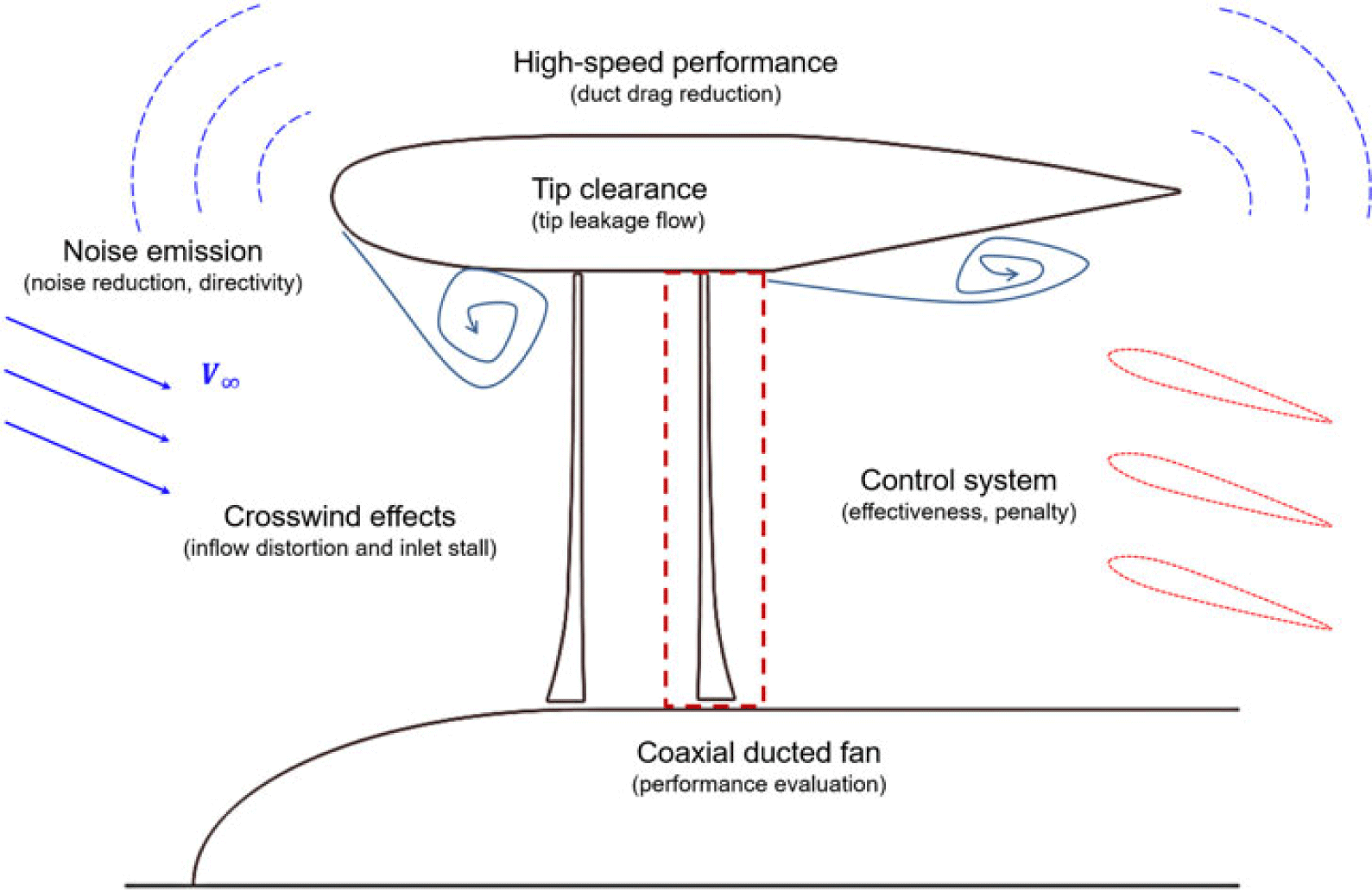
Figure 10. Ducted fan research challenges.

Figure 11. X-22A duct lip stall boundaries.(Reference Mort and Gamse20,Reference Camci and Akturk39)
4.1 Cross-wind effects
Non-axial inflow results in not only strong aerodynamic forces and moments on the duct, which behaves like an annular wing, but also in imbalanced disk loading that further induces more severe problems such as vibration. Flow separation at the inner or outer duct surfaces may also be encountered. As mentioned earlier, the separation depends on the difference between the fan power and the free-stream speed, the cross-wind angle, and the inlet lip geometry. In fact, several studies(Reference Taylor17,Reference Sheng, Zhao and Bi55) on fan-in-wing types reported lip separation in hover conditions. It is argued that there could be a critical lip radius of 6% duct diameter, below which separation would take place. However, as tested by Graf et al.,(Reference Graf, Fleming and Ng31) flow separation was also observed with a radius of  $12.5\%$. Further studies on lip effects were suggested by the researchers.
For tilt-duct aircraft, stall boundaries, as shown in Fig. 11, need to be specified to guide the flight attitude. The cross-wind effects are especially common and severe for ducted fan UAVs, since they tend to fly forward in an edgewise attitude and the Reynolds numbers are relatively low. Similarly, up-stream side flow distortion and separation result in an increase in drag forces and nose-up pitching moments.
Several methods have so far been proposed to alleviate the cross-wind effects, though mostly validated for UAV applications. A double-duct ducted fan concept was proposed by Akturk and Camci(Reference Akturk and Camci4) and Camci and Akturk(Reference Camci and Akturk39). The idea is to surround the duct with a larger secondary duct. The outer duct is used to adjust the wall static and dynamic pressure allocation, thereby eliminating the inner duct lip separation. Camci and Akturk conducted CFD simulations using actuator disks, and their effectiveness was compared. However, no comparisons with practical tests can be found.
Myers(Reference Myers65) proposed a more straightforward solution by adding vents at the forward flying side of the duct. The vented side almost gives up all benefits brought by the duct, and the asymmetry brings more imbalanced forces. Mechanisms can be introduced to actively open or close the vents according to flight conditions. Grunwald and Goodson(Reference Grunwald and Goodson8) proposed and examined an increased-radius lip solution that could effectively delay the inner surface separation. His solution resulted in an asymmetric duct since only the upper-stream lip was modified. Similarly, Bahram(Reference Bahram26) examined asymmetric duct (Fig. 7(k)) configurations, aiming at tilt-duct UAV applications, both experimentally and numerically. Comparing to a symmetric configuration, the asymmetric duct can provide lift forces and smaller force fluctuations during the transition from hover to axial flight. Nonetheless, such a solution may compromise the static performance and bring complexities in the duct geometry.
Actively morphing the duct geometry would be a much better solution for controlling flow separation. Ohanian et al.(Reference Ohanian, Karni, Londenberg, Gelhausen and Inman66) and Kondor and Moore(Reference Kondor and Moore67) applied synthetic jets at the inlet and outlet to insert momentum into the boundary layer, thereby triggering or suppressing flow separation. Further, inlet flow separation can be used to decrease the thrust. Such active flow control technique, that can be seen as a “virtually morphed geometry,” can be an effective way to exert control upon the performance at low speed cases. Its effectiveness on high-speed though needs to be verified. Applying collective and cyclic pitch control to the propeller blades, as implemented by Colman et al.,(Reference Colman, Suzuki and Kubo68) may also be an effective solution, but requires complex mechanisms and will have to be integrated in the small centre body inside the duct. Inlet guide vanes may also be effective in terms of regulating the inflow ahead the rotor disk.(Reference Gilmore and Grahame69)
Complexity, effectiveness, efficiency, and performance penalties should all be considered to determine the optimal choice. However, whether cross-wind stall remains a severe problem for propulsor applications is arguable. As concluded by Mort(Reference Mort23), the scale of the duct plays an important role in the stall characteristics. For ducted fans that are big enough, e.g. those utilised by the X-22A and the VZ-4, the inlet lip stall can only be encountered at very high rates of descent. Also, in Fig. 11, it can be observed that only mild up-stream inlet stall was encountered during the transition from hover to high-speed flight.
4.2 Tip clearance
The clearance between the duct inner surface and the blade tip leads to tip leakage flow. The presence of the duct significantly surpasses the extent of the blade tip vortices and regulates the flow to align with the duct surface, given a small tip-duct clearance. Several experiments, for instance Martin and Tung’s wind tunnel tests(Reference Martin and Tung30) on a 10-inch-diameter ducted fan, showed that the gap between the blade tip and the duct inner surface, significantly influences the overall thrust and the fan/duct thrust partition. Increasing the tip gap resulted in the thrust dropping quickly. It is also very difficult for wind tunnel experiments to investigate flow features of the tip leakage, due to the geometry of the duct, the very small tip clearance, as well as the blade rotation. CFD simulation represents a better choice in this respect.
Oweis et al. carried out a series of experiments(Reference Oweis, Fry, Chesnakas, Jessup and Ceccio70,Reference Oweis, Fry, Chesnakas, Jessup and Ceccio71) to study the tip-leakage flow. Although focused on marine applications, their experiments revealed that the size of the primary tip vortex is of the order of the tip clearance, and is not strongly dependent on the Reynolds number, or the boundary-layer thickness. Akturk and Camci(Reference Akturk and Camci34) combined numerical and experimental investigations for a 599mm-diameter ducted fan in hover, and confirmed that a smaller tip gap is beneficial. As shown in Fig. 12, through CFD flow-field visualisation, it can be seen that the primary leakage vortices impinged on the neighbouring blade, and the total pressure losses were noticed. As the tip clearance increased, the blade-vortex interaction region grew larger towards the mid-span. They also proposed several blade tip treatments,(Reference Akturk and Camci41) including modifying blade tip shapes and adding tip squealers, to mitigate the performance loss by reducing the leakage vortex strength or changing its trajectory. Matin and Boxwell(Reference Martin and Boxwell72) proposed a solution by adding a backward step on the duct inner surface near the rotor disk, but its effectiveness was not strong. More treatments, in terms of blade tip shape and duct shape modifications, or active flow control methods, should be studied and applied to aircraft applications.

Figure 12. Relative total pressure comparison with different tip clearances.(Reference Akturk and Camci34)
Recently, Ryu et al.(Reference Ryu, Cho and Cho73) studied the effect of tip clearance for a counter-rotating coaxial ducted fan UAV. Wind tunnel tests were conducted to validate the CFD simulations, while the flow details were studied using CFD. In that study, increasing the front and rear tip clearance caused the FoM to drop consistently. However, a smaller front rotor tip clearance, in combination with a larger rear tip clearance, delivered the maximum thrust observed. The thrust gain came from the rear rotor. This indicates that in a coaxial configuration, interactions between the two rotors add more complexity, and more detailed analysis is necessary.
4.3 High-speed performance
As investigated during many of aforementioned experiments, given the same propeller RPM, the efficiency of the ducted fan decreases as the advance ratio increases. However, the ratio of the propeller thrust to the overall propulsion increases in the mean time, indicating that the duct’s contribution is diminishing fast.
In high speed axial flight, the drag of the shroud may outweigh its benefits if not carefully designed. Early experiments by Krüger(Reference Krüger6) studied a high speed, high thrust loading ducted propeller model, aimed at reaching 400kg of thrust at 80km/h, and at an altitude of 8.6km, when scaled to full size. The results showed that as the forward advance ratio increases, the propeller thrust coefficient can be maintained with larger blade pitch, but the duct thrust drops quickly and consequently the overall thrust decreases with increasing advance ratio. The experiments also suggested that high speed efficiency can be significantly increased by adopting shroud profiles with smaller chord and thickness, yet this is accompanied by a static performance penalty (that could be mitigated by an outward nose ring). Grunwald and Goodson’s experiments(Reference Grunwald and Goodson8) also found that the propeller to overall thrust ratios increased from 40% to 70% as the forward advance ratio increased from 0 to 0.595 at zero angle-of-attack, indicating a reduction of the duct efficiency at high speed. The experiments of Abrego et al.(Reference Abrego, Bulaga and Rutkowski28) on a 38-inch diameter, fixed-pitch ducted fan, showed that with increasing advancing ratio, the thrust coefficient and efficiency drops quickly.
More recently, Biava and Barakos(Reference Biava and Barakos57) investigated the effect of the duct using high-fidelity CFD methods and concluded that the duct has a significantly positive effect on the overall thrust and efficiency at low speeds. As an extreme, at zero propeller advance ratio the ducted fan could generate 24% more thrust with 25% less power. The visualisation of the flow-field pointed out that the rear part of the duct serves as a diffuser to slow down the wake speed and increase the static pressure, thereby increasing the overall thrust comparing to the free propeller. The efficiency, however, gradually decreases as the advance ratio increases and eventually becomes negative. It is reasonable to conclude that the deficiency is mostly attributed to the greater duct drag caused by the higher speed. Geometric optimisation of the duct rear part was also applied, resulting in a shorter chord length, and a higher expansion ratio, bringing a small performance improvement.
4.4 Noise emission
The ducted fan noise is a separate topic of research. Noise emission of fans enclosed by a duct of finite/infinite/semi-infinite length has attracted great research interest during the past decades. Applications can be found in turbofan/turbomachinery(Reference Rumsey, Biedron, Farassat and Spence74–Reference Reboul, Polacsek, Lewy and Heib76) and environment control device(Reference Shur, Strelets, Travin, Christophe, Kucukcoskun, Schram, Sack and Åbom77) noise predictions. A more comprehensive review in this respect can be found in references(Reference Eversman78–Reference Astley, Sugimoto, Achunche, Kewin, Mustafi and Deane81).
The ducted fan noise mostly comes from the rotating fan and interactions of its wake with the stator/vane. The presence of the duct substantially modifies the acoustic characteristics of a rotating fan/propeller. Stronger radiation directivity and noise reduction, compared to an open propeller, are the two major features as confirmed by several calculations and experiments. Since the first work by Tyler and Sofrin(Reference Tyler and Sofrin82) in the 1960s, theoretical/numerical analysis of duct-rotor acoustics has seen significant development. Dunn et al.(Reference Dunn, Tweed and Farassat83) presented a boundary integral equation method for ducted fan noise prediction, and a prediction tool named TBIEM3D(Reference Dunn84) was developed. The methods were examined by simulating the noise emission of a 20-bladed fan located in the middle of a finite length duct. Twenty(20) spinning point dipole noise sources were placed symmetrically on the fan disk, and the results clearly showed the directivity of the ducted fan noise radiation. In their study, the acoustic pressure was shown to be concentrated around  $45^\circ$ off the rotor rotation axis up-stream and down-stream. The axial and normal directions were left to have minimal sound radiation. The results were compared later by Wang et al.(Reference Wang, Yang and Guan85) using FW-H based methods, and good agreement was noticed. That study complements Hubbard’s early experiments.(Reference Hubbard15) Choi et al.(Reference Choi, Jeon and Lee86) simulated the discrete tones of a ducted acoustic source, and also suggested a similar directivity pattern and noise reduction, due to the presence of the duct. Dunn et al.(Reference Dunn, Tweed and Farassat83) also included lined surfaces to evaluate the noise reduction. It was found that inlet and outlet lining is very effective in mitigating the noise radiation.
Most studies mentioned earlier focused on many-bladed, high solidity fans. Though phenomena such as duct reflection and scattering, and rotor/stator interactions, are believed to be similar, fewer analyses can be found for lower solidity ducted fans. Differences in the blade number, RPM, pitch angle etc. may result in a shifted characteristic spectrum. As mentioned earlier, Hubbard(Reference Hubbard15) compared sound-pressure measurements of five duct-propeller combinations in hover, with an open propeller at approximately the same rotational speed and power. The geometries of the four ducts, and the two blades tested, along with the test conditions were reported in detail. Total sound pressure, measured 30 feet away, produced by the two-blade shrouded propeller, was constantly lower at all measured angular stations, given no flow separation was present. The maximum measured value was around half that of the open propeller. The measurements also showed clear directivity of the sound radiation. The maximum value was around  $70^\circ$ relative to the rotation axis downstream, while another smaller spike was spotted at about
  $50^\circ$ upstream. Lower values were noticed in axial and normal directions to the outer duct surface, with the lowest values along the inflow axis. The results showed that the duct reduced the strength of radiated sound and redistributed the sound energy in different directions. However, when the RPM and rotor power were slightly reduced, and flow separation was present at the inner surface near the inlet lip, excessive sound pressure was recorded. The measurements were almost twice as high as the two-bladed open propeller in all directions, and the directivity pattern was maintained. The tests also investigated factors such as the duct chord length, tip clearance, tip speed, and blade number. It was eventually concluded, as also briefly summarised by Bulaga(Reference Bulaga87) later, that many factors which promote the aerodynamic performance also reduce noise emissions, e.g. smaller tip clearance and avoiding flow separation. Reduced RPM and increased blade numbers provided better acoustic performance, while the duct chord length had minor effects on the acoustics. The tests, however, were conducted outdoors, hence environmental uncertainties could not be eliminated. Regardless, the study revealed that separation, which was likely to appear at low rotational speeds, leads to higher sound pressure levels. Hubbard’s works provided the exact geometry of the ducts and blades (including blade sections). However, limited aerodynamic performance data, which was extracted from the duct surface pressure measurements, was presented.
Recent small-sized experiments reported insignificant or negative noise reduction due to the duct. Martin and Boxwell(Reference Martin and Boxwell72) studied the acoustic characteristics of a 10-inch-diameter ducted fan UAV. They concluded that the shroud does not alter the blade passage frequency noise, but increases the level of the broadband noise component. The influence of the tip clearance was reported as insignificant, but the separation at the inlet lip was found to increase the broadband noise contributions. Rhee et al.(Reference Rhee, Myers and McLaughlin35) also conducted a series of wind tunnel tests to study the acoustic characteristics of the ducted fan without cross-wind effects. The comparisons showed that the noise level of the ducted fan was slightly higher than for open rotors when producing the same thrust. The directivity feature of the ducted fan noise was also presented, and was shown to be consistent with Hubbard’s tests.(Reference Hubbard15) They suggested that a perforated liner installed inside the duct would effectively reduce the noise. Reasons for the opposite conclusions are not certain, but they might be related to the low Reynolds numbers and flow separation.
Very recently, Malgoezar et al.(Reference Malgoezar, Vieira, Snellen, Simons and Veldhuis88) conducted acoustics experiments on a 30-cm-diameter ducted propeller with a Clark-Y profile. Variations of acoustic source types (an omni-directional source and a propeller) and cases at advance ratios were considered. Comparisons were also made between the ducted and the isolated configurations. The duct was shown to have a significant impact on the frequency distribution and directionality, and noise reduction could be noticed for cases with inflow. For static, hover state, however, noise increase was observed for most harmonics, while the frequency distribution resembled more an omni-directional source. Beamforming was then utilised to discern the acoustic sources, and a new noise source is identified at the duct leading edge. It was argued that the resonance of the duct and the interaction between the blade vortices and the duct boundary layer were the reasons behind the noise increase.
Compared to an open propeller, the acoustic performance of the ducted fan can be expected to be superior, as the duct provides a basis for further nose treatments e.g. inlet/exhaust liners. Further experiments and high-fidelity simulations on ducted fan noise should, however, be carried out to explore the acoustic benefits. For future VTOL aircraft, ducted fans show great potential especially on stringent noise limits to be imposed on future rotorcraft.
4.5 Control systems
Effective and efficient control of ducted fan performance is another aspect of this survey. Guide vanes are more commonly deployed to vectorise the propulsor thrust. For UAV applications, several methods, as mentioned earlier, such as active flow control at the inlet and outlet,(Reference Ohanian, Karni, Londenberg, Gelhausen and Inman66,Reference Kondor and Moore67) cyclic pitch control of the blades,(Reference Colman, Suzuki and Kubo68) inlet spoiler,(Reference Fleming, Jones, Ng, Gelhausen and Enns29) exit rotating cylinder using Magnus effects,(Reference Zhao, Hou, Jin, Zhu and Li89,Reference Hou, Zhu, Zhao, Li and Jin90) etc. show potential for application. Nonetheless, their actual effectiveness and efficiency on aircraft applications remain unclear.
The inlet vanes are capable of altering the effective blade pitch angle, thereby adjusting the overall thrust distribution. In fact, the inlet guide vanes are also useful for regulating the inflow and alleviating the inflow distortion. Outlet vanes are better for deflecting the flow and generating side forces. Nevertheless, all guide vanes bring blockage and weight. Gilmore and Grahame(Reference Gilmore and Grahame69) tested inlet and exit guide vanes on a 28.56-inch diameter, fan-in-wing ducted fan model in transitional flight. Ten(10) inlet vanes were allowed to turn individually according to the inflow conditions, while the exit vanes were linked collectively. The experiments showed that the transition performance was improved, by using the inlet vanes for inflow regulation and the exit vanes for aircraft control. As expected, a small performance penalty at static conditions was noticed.
Experiments of the 4-foot ducted fan(Reference Yaggy and Mort18,Reference Yaggy and Goodson24) also examined both inlet and outlet guide vanes. The experiments concluded that the exit vanes are more effective than the inlet vanes. Abrego et al.(Reference Abrego, Bulaga and Rutkowski28) examined a ducted fan with two 3-inch chord exit vanes, and concluded that exit vanes with flaps are effective in generating side forces. Using a symmetric installation of vanes and deflection angles ( $\pm 40^\circ$) the force coefficients were not symmetric, and with zero deflection, slightly positive side-forces were generated. This might be the result of manufacturing defects of the model, as suggested by the authors, but it may also be related to the tangential induction of the rotating rotor. Mort and Gamse(Reference Mort and Gamse20) worked on a full-scale ducted fan with a large vane, and showed symmetric force changes against symmetric deflection angle changes. They also reported that at positive vane deflection angles, the effectiveness of the vane was significantly lower than expected as the cross wind angle was increased. Such asymmetry may also be related to the arrangement of guide vanes. For most tests mentioned herein, the vanes were aligned either in columns or rows, which in itself represents an asymmetry. Other arrangements, such as even distributions along the radius or angular directions, should be considered and evaluated.
Active flow control and cyclic blade pitch control might be possible solutions, as well, but performance penalties should be carefully evaluated. It is to be noted that only few experimental studies considered the effect of the guide vanes, and relevant numerical studies can hardly be found.
4.6 Coaxial ducted fan systems
Adding a second row of rotor blades to the ducted propulsor is important either for emergencies or torque balancing. As mentioned earlier, the contra-rotating coaxial design is also essential to make the ducted fan a compact, removable propulsion unit, which has great potential for future eVTOL aircraft. However, as stated earlier, more complexity in performance analysis should be expected due to the interaction of the two rotors.
Concerning the contra-rotating coaxial ducted fan system, few studies can be found in the open domain and most focused on UAVs, such as the Sikorsky Cypher UAV developed in the late 1990s. Lee(Reference Lee91) tested both contra-rotating and single-rotor ducted fan UAV models. He found that, in contrast to the ducted single rotor, shrouding a contra-rotating rotor does not always deliver better performance. Sensitivities to different design parameters, e.g. inlet radius, tip radius, and propeller location, are important. Based on Lee’s work, Geldenhuys(Reference Geldenhuys92) studied a similar coaxial system numerically, using the same duct geometry but used a different rotor design. The DFDC code and incompressible CFD simulations were used for the analysis. The results and experiments matched well, in general, but differences were presented for several cases. It is notable that the DFDC configuration file and elaborate geometric information were provided, making it possible for further validation and investigation. Jiang et al.(Reference Jiang, Li and Jia93) conducted combined numerical and experimental studies on a general coaxial ducted fan configuration. The study mainly investigated three factors: the blade pitch angle, free-stream speed and the rotor spacing. Combinations of these factors gave distinct performance results, yet the CFD results agreed with the experiments very well. Nemnem et al.(Reference Nemnem, Zakaria and Elzahaby94) discussed the parameters of coaxial ducted fan design, but the study lacks the support from either experiments or simulations. Overall, performance and determining factors of the coaxial ducted fan need to be further investigated.
5 CONCLUSIONS
This survey of published works resulted in the following conclusions:
1. Research on large-scale ducted fans for propulsion purposes mostly emerged between the 1950s and 1970s. Most recent research focused on small-scale UAV applications.
2. Detailed theoretical studies and several lower-order methods for ducted fan performance prediction are available. Higher-order simulations with CFD are within the capability of modern numerical methods and computational resources.
3. Effective treatments for high AoA distortion/stall, and high-speed performance at high Reynolds number, such as blade tip modifications, asymmetric duct design, deformable geometries, or active flow control methods, need to be investigated.
4. Numerical simulation and multi-objective optimal design of ducted fans should be attempted, and components like stators, second rotors, and guide vanes should be considered.
5. More experiments on ducted fan noise emission should be carried out, and numerical studies should also be explored.
6. Application and performance of ducted fans on compound rotorcraft should be considered and evaluated.
Overall, the ducted fan is a favourable choice as an auxiliary source of lift/thrust for novel rotorcraft configurations considering its benefits, in terms of efficiency, safety, and compactness. However, during the design process, treatments and improvement for cross-wind effects, high-speed performance, noise emission, effective and efficient control system must be investigated and evaluated.
ACKNOWLEDGEMENTS
The sponsorship of the University of Glasgow and the China Scholarship Council is gratefully acknowledged. The authors are also grateful to the handling editor and the anonymous reviewers for their supportive comments and meticulous reading of the paper.