


NOMENCLATURE
- λ
Rate of failure per unit time
- cm
Criticality of subsystem m
- Sm
Subsystem m
- Rm
Reliability of subsystem m
- Rsys
Reliability of overall system
- Sall
Union of all subsystems
- ALU
Arithmetic and logic unit
- AMP
Asymmetric multiprocessor
- FCS
Flight control system
- FPGA
Field programmable gate array
- HDL
Hardware description language
- IMU
Inertial measurement unit
- PID
Proportional-integral-derivative
1.0 INTRODUCTION
Reliability is the key aspect when considering operations of unmanned aircraft systems (UAS), or drones, in close vicinity to people. The reliability aspect of the embedded flight controller for UAS was neglected earlier, probably because faults were often encountered from other physical components. Recent research outcomes in control algorithms have made it possible to keep the craft airborne even after failure of major subsystems(Reference Mueller and D’andrea1) that gives us the motivation to put effort towards a reliable embedded flight controller platform.
Conventional solutions to improve reliability in embedded platforms is achieved by extensive hardware redundancy, which is not feasible for agile aerial platforms due to space, weight, and power (SWaP) constraints. In a generic UAS embedded flight computer, the applications with different level of criticality share the same hardware due to tight SWaP budget. Operation or failure of one application can cause interference that might cause malfunction in other applications or even the entire system, compromising the overall reliability. Although the software implementation of conventional flight control algorithms are widely evaluated and considered reliable, the payload/mission specific applications, implemented by the end-user, can have higher complexity and can be hard to analyse, hence, may have imperfections.
An isolation mechanism is beneficial for fault containment and prevention of interapplication interference. A hypervisor and embedded operating system (Reference Döbel, Härtig and Engel6) can provide such an isolation in software by restricting the access of individual applications to shared resources up to a certain degree. However, implementing software-based safety mechanism is a complex task that becomes even more complex for mixed-criticality system and multicore implementation(Reference Alhakeem and Munk9). Additionally, the protective software (e.g. an operating system) consumes significant amount of computational resources. Distributed and redundant implementation in isolated partitions in embedded platforms are done by considering the reliability of the subsystems of the system. For safety-critical systems, like UAS, analysing the criticality of the subsystems is important for efficient distribution. In the aviation industry, such criticality levels are analysed, and systems with different criticality levels are kept isolated, which is not feasible for low-cost platforms.
In this work, we present a distributed implementation of a conventional flight control system (FCS) software on a custom multiprocessor architecture, that establishes isolation at hardware level. The proposed distribution method considers reliability as well as criticality of the subsystems for distributed implementation to minimise the probability of system failure; which we define to be a loss of control situation. For implementation on a resource limited platform, applications with different levels of criticality and reliability are allowed to share the same processor. Each processor is an independent system, with dedicated and isolated resources, connected to a protective inter-connect for inter-processor communication with message-passing technique. Establishing isolation at hardware level provides the benefits of a distributed and bare-metal implementation with ease of scheduling and execution time analysis. Furthermore, such a platform is free from the complexity of multi-threading and offers reusability of applications developed for single processor systems.
The paper is structured as follows. Section 2 gives an overview of related works and presents regulations for unmanned aircraft and its subsystems. Section 3 provides an insight of a generic FCS architecture and functionality of different subsystems. Section 4 introduces the proposed system architecture and its components followed by implementation of a FCS in the architecture in Section 5. Section 6 presents an analysis of fault-tolerance under some given condition. Experimental results are presented in Section 7 and Section 8 concludes the paper.
2.0 BACKGROUND AND RELATED WORK
Despite the fact that the dynamics and control of manned and unmanned aircraft systems are very similar, the software implementation in unmanned aircraft system is very different. Apart from the quality regulations and certification standards, the distributed and redundant control structure in manned aviation makes it more reliable where a single failure can hardly result in a catastrophe. Moreover, separate hardware and system isolation prevent interference.
The advancement in FPGA technology has made it possible to develop application-specific custom processor architectures, and asymmetric multiprocessor (AMP) architectures have gained the attention of researchers. Unlike synchronous multiprocessors where processors are connected to shared memory, in AMP architecture processors are distributed in clusters and resources are shared within a cluster only. Such architectures have been under consideration for safety-critical applications. In(Reference Lo, Valot, Maraninchi and Raymond7), researcher have investigated such a platform for avionics implementation, where a health monitoring system of a helicopter is implemented in a many-core architecture. The authors considered the regulations for airborne systems, and isolation was established between subsystems of different criticality level.
Established solutions for safety-critical applications largely depends on availability of resources for recovery. In(Reference Aggarwal, Ranganathan, Jouppi and Smith5), such a redundant implementation is discussed. In resource-limited platforms, such availability of resources is not feasible. The researchers in(Reference Gizopoulos, Psarakis, Adve, Ramchandran, Hari, Sorin, Meixner, Biswas and Vera3) introduced an in-operation error detection and recovery technique and proposed novel methodologies for efficient resource utilisation in redundant hardware. An adaptive approach with a dynamic scheduling solution is provided in(Reference Bolchini, Miele and Sciuto4). For efficient resource utilisation in multi-core architectures load balancing techniques are considered where effort is given to distribute the computation tasks evenly on the available processors. Such practice of distributed implementation is beneficial for general purpose computation in terms of overall throughput and power, but for safety-critical applications considering reliability and criticality of the tasks is important. In(Reference Littlewood and Strigini14) and(Reference Finkelstein11) the reliability and dependability of software implementations for different application of different size and functionality is presented. The authors have described several approaches of estimating achievable software reliability under different conditions. In(Reference Reliability15), the author has described software reliability modes, including system availability, safety, security, and criticality aspects of software.
In(Reference Zhang and Pham13), field failure rate of an integrated software system is analysed prior to field deployment, where a field failure rate prediction methodology is described by considering system test data and field data using software reliability growth models. Such a methodology gives an estimation of software reliability in a targeted platform before the actual deployment of the software. The authors in(Reference Song, Chang and Hoang12) propose a new software reliability model that takes into account the uncertainty of operating environments, that is helpful for estimating the reliability of the software implementation in a hardware environment that is different from the one, for which the software was developed and tested.
3.0 FLIGHT CONTROLLER ARCHITECTURE FOR UAS
The objective of an effective flight controller is to reach desired state at desired time instant by wisely manipulating the actuators, considering the dynamics of the vehicle. Although the implementation of a flight controller varies with the dynamics of the platform, the control architecture is very similar for conventional fixed wing and multirotor platforms.
A conventional flight controller consists of multiple cascaded closed-loop controllers, where the control command flows from the outer loop to the inner loop. The inner-most loop is closely coupled with the physical actuators that establishes link between the plant (the UAS platform) and the controller. Required control loop frequency depends on the application, environmental factors, and dynamics of the platform.
A multirotor platform has faster dynamics compared to a fixed-wing platform of similar size and weight, and requires a faster control response for controlled maneuvers. For this reason, this work will present the proposed method as applied to a FCS architecture for a multirotor platform.
A multirotor is controlled by actuating the thrust from each rotor, by manipulating the angular velocity of the rotors. The inner-loop controller, typically an angular velocity controller, is a closed-loop controller that controls the angular velocity of the multirotor by directly controlling the rotors by taking desired angular velocities as a reference signal from the attitude controller and actual roll, pitch and yaw motions (from an on-board sensor/estimator) as feedback signal as shown in Fig. 1. The attitude controller gets references from a translational velocity controller, which in turn depends on a position controller and ultimately a trajectory planner. In a hover condition, where reference signals are zero, the angular velocity controller controls the rotors to hold the multirotor in a horizontal position.
The position controller is a feedback controller that takes a reference signal from a trajectory planner, feedback signal from a positioning device (such as GPS or motion capture system) and outputs desired attitude state variables that is fed to the attitude controller as an input. A trajectory planner could have very different approaches of generating output signal in the form of position (x′, y′, z′) or position-velocity (x′, y′, z′, u′, v′, w′) combination that goes into the position/velocity controller(s). A vast range of different approaches like way-point navigation, vision-based navigation, vision-IMU odometry, genetic algorithm etc. are used for trajectory planning.

Figure 1. Block diagram of a generic FCS implementation, where inner to outer loops are represented in a right to left order. [θ′, ϕ′, ψ′, h′] is the reference attitude and altitude. [ax, ay, az, P, Q, R] are accelerations and angular velocities respectively.
3.1 Sources of failure and effects
A system failure in this context can be defined as an uncontrolled, unrecoverable maneuver resulting in a crash of the platform. This work considers the failure related to the FCS only, and not failures related to mechanical, power or external peripheral (GPS/motion capture device) failures. We have considered that the operation of the UAS is completely autonomous and there is no pilot input to avoid human error.
Failure in different control loops with different functionality has different effect on the system. The source of failure could be in the algorithm, in software implementation, in the dependencies, and even in the computing platform, i.e. embedded computer. It is also vital to consider the response time of the control loop, as a delayed response is also considered as a functional failure in control application.
The inner-loop is the most critical control loop in the system, as a failure at this level results in loss of control with a very high probability. However, a proportional-integral-differential (PID) controller, the widely used control algorithm in the inner-loop is fairly simple, deterministic, and easy to implement in software. The effectiveness of the inner-loop heavily relies on the attitude sensor/estimator output and redundant sensors are used to increase reliability. Assuming, the external devices are fault-free, the only possible source of failure in the inner-loop could be interference from other applications or a failure in the computational platform. The position controller is similar to the inner-loop where a PID controller is widely used to compute reference attitude/thrust control commands to hold or attain a reference position in a three-dimensional space. The position controller itself is reliable, however, its dependency on an external positioning system (e.g. GPS) can reduce its reliability in terms of timely computation of control commands. A failure in the position-controller is not necessarily catastrophic, as a controlled descent is still possible with the inner-loop controller alone; however, an uncontrolled drift may result in a crash of the platform.
The trajectory controller may use complex algorithms to compute desired trajectories and its software implementation can be hard to analyse for errors. Algorithms like way-point tracking is fairly simple, and a deterministic implementation is possible. However, most of the autonomy comes from the life-long trajectory planning where the trajectory is planned or updated on the go based on the updated information of the surroundings. Such iterative computations may result in memory overflow or infinite looping. Although a failure in the trajectory controller would not necessarily lead to a loss of control, it can significantly interfere with other applications when sharing the same computational platform.
Table 1 Supported data operations by the ALU

4.0 SYSTEM ARCHITECTURE
In this section, we will discuss the architecture of the proposed system and the architectural benefits in the context of isolation. For designing the custom platform architecture, the following assumptions are considered.
1 The software is directly implemented without any operating system or any other software-based protection mechanism.
2 A malfunctioning software subsystem can adversely affect other subsystems sharing the same processor.
3 All subsystems can run on any of the processors.
The design goal is to establish isolation at the hardware level to prevent interference between processes such that no subsystem can interfere subsystems in other partitions or the entire system under all possible conditions to ensure a reliable computation framework for critical control applications. The idea behind this work is to consider a multicore architecture for an agile aerial platform with limited resources. Therefore, the focus is to reduce the footprint of the custom hardware implemented on FPGA thread for possible implementation on very small and low-cost platforms.
4.1 Processor
The system has four processors and each processor in this architecture is an independent system with its own I/O, cache, data memory, instruction memory, heap and stack and no memory is shared between two processors. The complete isolation prevents any kind of interference between the processes running on each processor.
The processor considered in this work is a 32-bit RISC processor implemented with separate 32-bit wide data and 16-bit wide instruction memories. The capacity of the data and instruction memory are configurable and depends upon application needs and available physical resources. The separate instruction and data memory allow fetching of an instruction in every clock cycle. For simpler implementation of different width of data and instruction, the processor does not support ‘immediate’ and all the operands are stored in the data memory. Each processor has eight 32-bit general purpose registers that are used for computation. The ALU operates on the data stored in the general purpose registers or in the data memory and stores a result in the general purpose registers or in the data-memory. The supported data operations by the ALU are described in Table 1.
Each processor has an internal 32-bit counter that can be directly accessed by the ALU with specific instruction. Furthermore, each processor is equipped with an internal watchdog with a 32-bit counter. On a start or reset condition, the program counter of the processor is set to the code entry point of the instruction memory associated to the processor, the general purpose registers in the processors are initialised to zero and the watchdog counter is set to zero.
4.2 Memory
Memory is a critical element for establishing isolation. Erroneous applications can corrupt memory allocated to itself or memory regions of other applications. In this work, the memory device used are on-chip memory only and off-chip memory is out of the scope of this work. The memory is defined in HDL and the synthesis tool targets the on-chip memory blocks on the the FPGA for synthesising memory on the hardware. The memory shares clock with the processor. The memory blocks allocated to each processor are physically isolated. Application running on a processor can only access the data memory assigned to that specific processor. Furthermore, the separate implementation of data memory and instruction memory helps to prevent corruption of the executable code. The memory writing mechanism of the instruction memory is only accessibly to a program downloading mechanism that is used for writing the executable code in the instruction memory by the user. The user can program and reprogram the instruction memory and can read the instructions for verification as a RAM device. However, the processor can only read from the instruction memory, as a ROM device. It is the application developer’s responsibility to fit the application in the memory allocated to a processor to prevent overflow. The executable code needs to be uploaded separately to each isolated instruction memories, which can be different or same for each processor depending upon the user need.
The memory operations are single cycled, the processor requests data from a memory location and reads the data in the subsequent cycle.
4.3 Peripherals
The access to external devices (sensors and actuators in this case) is restricted to the associated applications only to establish isolation, and a memory mapping approach is adopted to map the data-registers of the IO devices in the memory region allocated to the individual processors as shown in Fig. 2. In this configuration, specific addresses from each partition is dedicated to memory mapped devices. The memory-mapped address share the same interface with the data memory. The read–write request for the memory mapped addresses are bypassed to the IO-devices (IP Cores) by a memory-interface mechanism implemented in hardware by controlling the chip-select line. The physical memory location at the addresses of the memory mapped devices cannot be accessed and remains unused at the upper edge of each memory partition. A processor reads 0, if an IO-device is not present at a dedicated memory-mapped address.
4.4 Reset IPCore
A reset mechanism is necessary to reset the processors when a fault is encountered. In most platforms a universal reset is used to restart all processors and other components. The isolated implementation in this architecture allows implementing an individual reset mechanism where any particular processor can be reset without affecting the other components in the system. The custom reset hardware is connected to the on-chip interconnect where any processor can send a reset request for itself or other processors. Once a reset request is received for a processor, the reset line of that processor is held active for one clock cycle. This hardware is beneficial for fault recovery as discussed in later sections. The reset IPcore can be a single point of failure for the system, however, it is defined in a simple and analysable form with a small footprint, therefore, assumed to be reliable.
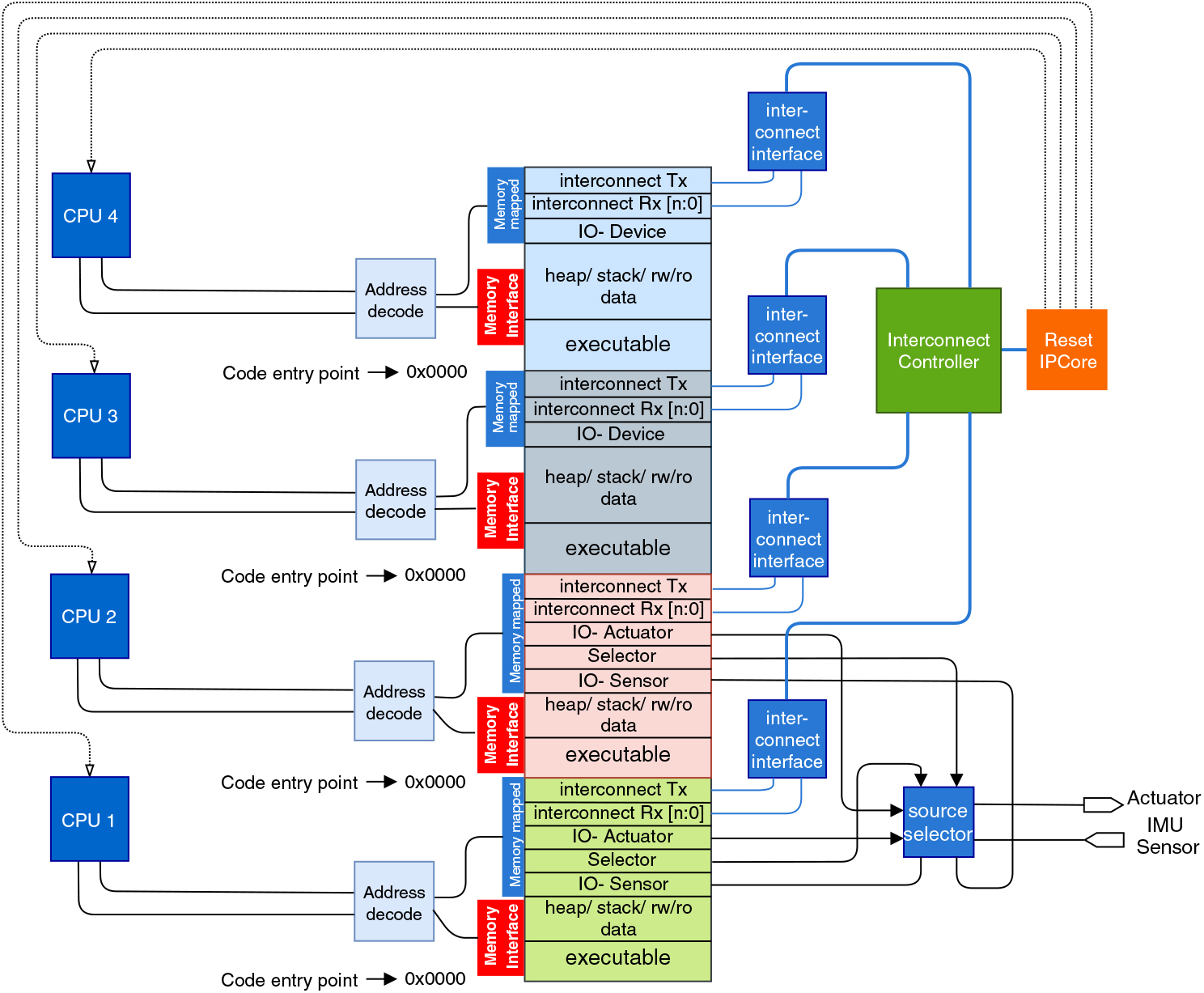
Figure 2. Block diagram of the proposed architecture in a four CPU configuration.
4.5 Source selection
In a system with multiple producers and consumers, a source control mechanism is essential. A polling based source selection mechanism is established practice for redundant architectures with N-redundant systems. In the proposed architecture with limited resources a polling based source selection mechanism is not effective. The sources selection IPcore controls the data flow between processors and peripherals where more than one source is present. The data flow from sensors to processors is simple, where the IPcore forks the sensor data to multiple processors without any control. The actuators cannot handle simultaneous input from more than one source, moreover, simultaneous write from two separate functional sources can result in an unpredictable and erroneous data-write and a flow control mechanism is necessary. The IPCore has an internal counter and four 8-bit registers for each propulsion unit where each processor can write the control command (i.e. thrust command in percentage in this case). The source selection IPcore forwards the command from the default register to the propulsion controller i.e. PWM generator in this case. If a fresh command is not received before a timeout period, the IPcore selects the next register as the default register.
4.6 On-chip interconnect
As there is no shared memory in this architecture, a message passing approach is taken for inter-processor communication to share data between applications running on separate processors, where application running on one processor can send data as message-packets to a destination processor connected with an interconnect. The interconnect has special mechanism for data-protection, isolation, and real-time end-to-end on-chip communication.
4.6.1 Micro-architecture
The interconnect has two components; an interface for each processor and a controller. The interface is an on-chip memory-mapped device where the transmitting and receiving buffers are independently mapped to the memory region of associated processor. The interface takes two address spaces for transmission, one for the data-packet and the other for destination address, and one address space for each receiving channel. The destination address is the destination processor id followed by the channel id.
Each interface has dedicated sampling buffers for each transmission and reception channel, where the data-packets are held before transmission and stored after reception for the consumer application to read. The dedicated sampling buffers hold single data-packets from the associated channel unless a new-packet from the same channel over-writes the packet or it gets consumed by the consumer. Each interface has an independent transmission and reception line, a single bit request line, a single bit access line and a single bit active line to connect with the controller. The transmission and reception lines from each interface are connected to the controller with a cross-bar.
The controller controls the communication over the interconnect by providing transmission access to the interfaces. The controller has separate request, access, and active line connecting each interface. The controller is memory-less and the flow through the controller is atomic.
4.6.2 Operation
At the beginning of a transmission, a producer (sending application) writes the message and the destination address at the memory mapped transmission address of the interface. When a fresh data-packet is received at the interface, the interface raises a transmission request to the controller. A round-robin arbitration is implemented in the controller to provide transmission access to each interface by holding the associated access line high. Once access is gained, the interface keeps transmitting until all data-packets are transmitted or access is taken back by the controller (access line is low). The controller checks for the destination processor address in the header of the data-packets and forwards the packet to the destination interface by controlling the x-bar. The destination interface reads the channel id in the header and holds the message in the associated channel buffer.
Channel specific sampling buffers provide an isolation mechanism; unlike conventional FIFO buffers, overflow in one channel has no effect on the data in other channels. Additionally, the access is controlled by the on-chip controller, dysfunction in an application cannot over-load the system, as the controller only forwards the data-packets from an interface, when transmission access is given to the interface.
5.0 DISTRIBUTED IMPLEMENTATION
This section addresses the distributed implementation strategy of a conventional FCS in the proposed architecture. The design goal is to achieve higher reliability of the entire system to reduce the probability of a loss-of-control failure.
Distributed implementation does not necessarily provide improvements in reliability. In order to achieve improvements we have to provide a reasonably intelligent distribution of functionality on the available processors. In our setup, these functionalities are provided as function calls in a programming language and, in the following will be called subsystems. Any functionality can be provided by more than one subsystem, but will then be programmed differently to achieve some degree of independency. Thus, the FCS consists of a number of subsystems, as shown in Fig. 2.
5.1 Reliability and criticality
One method for determining the optimal distribution is to assign a reliability function to each functionality and simply pick the distribution that provides the better overall reliability. In addition to this, we are also interested in optimising for criticality, that is finding the distribution with the least probability of losing control of the aircraft. Criticality of a subsystem is determined by the possible impact on the system on the event of dysfunction in that particular subsystem. Each subsystem is assigned a criticality that expresses the importance of the subsystem being operational. Importance is to be understood in terms of aviation safety, where failure of a critical subsystem is more likely to lead to loss of the aircraft than failure of a less critical subsystem. For instance, maintaining attitude control of the aircraft is much more important than completing the mission of the aircraft. Subsystem criticality is quantified as a number between 0 and 1, with 0 being non-critical and 1 being very critical for maintaining control of the aircraft.
We impose the following assumptions on these subsystems.
1 Each subsystem is either operational or it has failed.
2 Failure of a subsystem results in failure of the processor it is running on, and thus of all other subsystems running on the same processor.
3 An operational subsystem produces correct results.
4 A known reliability function R(t) is associated with each subsystem.
5 A known criticality index is associated with each subsystem.
6 The number of processors available on the platform are limited and known to the system designer.
7 Two subsystems can have the same functionality, but with different implementations. The subsystems are said to be redundant. It is assumed that redundant subsystems are independent. We will use the term ‘functional subsystems’ for subsystems with different functionalities.
8 A payload or foreign application software is not analysed and might have imperfections.
The analysis only includes the algorithmic parts of the FCS. Thus, we assume sensors and actuators to be perfectly reliable.
5.2 Reliability analysis
The reliability R(t) of a subsystem is the probability of non-occurrence of a subsystem failure up until time t. When two subsystems are interdependent, meaning that if one fails the systems composed of the two subsystems also fails, the joint reliability is
 $$\matrix{ {{R_{{\rm{sys}}}}\left( t \right) = \coprod\limits_{k = 1}^n {{R_k}} \left( t \right).} & { \ldots \left( 1 \right)} \cr } $$
We say that the subsystems are in series. If two subsystems are independent, meaning that the system composed of the two subsystems will continue to function correctly if either of the two subsystems fail, the joint reliability is
 $$\matrix{ {{R_{{\rm{sys}}}}\left( t \right) = \left( {1 - \coprod\limits_{k = 1}^n {\left( {1 - {R_k}\left( t \right)} \right)} } \right),} & { \ldots \left( 2 \right)} \cr } $$
and we say that the subsystems are in parallel.
As stated in assumption 2 above, when subsystems run of the same core a failure of one subsystem is assumed to render the entire core inoperable. Therefore, any subsystems running on the same core will be in series. Redundant systems, as described in assumption 7, are in parallel. So, if subsystems S 1 and S 2 are redundant implementations of the same functionality, with reliability functions R 1 and R 2, respectively, the joint reliability R 3(t) of the combined systems of S 1 and S 2 is
 $${R_3}\left( t \right) = 1 - \left( {1 - {R_1}\left( t \right)} \right)\left( {1 - {R_2}\left( t \right)} \right).$$
For the entire system to operate all non-redundant subsystems must be functional, where a non-redundant subsystem is either a functionality that does not have redundant implementations, or the joint system of a number of redundant subsystems implementing the same functionality. That is, the non-redundant subsystems are all in series.
5.3 Criticality and optimisation metric
So, if all subsystems were equally critical for the complete system to function, and no redundancy of subsystems were employed, the resulting reliability would be as given in (1). However, in many instances of subsystem failures an FCS is able to avoid loss of control. If, say, the trajectory planner fails the aircraft may not be able to complete its mission, but the FCS is still able to maintain sufficient control of the aircraft to conduct a safe landing (thus avoiding loss of control). Consequently, we assign a criticality somewhat less than one. However, if, say, the attitude controller fails the likelihood of loss of control is very high, since not controlling the attitude of the multirotor will most likely lead to a crash. Thus, we assign a criticality close to one.
Assume that we have a setup with N cores, and M subsystems with separate functionalities, that is, subsystems each implementing a specific functionality, such as trajectory planner or velocity controller. In addition, we have M r subsystems that each provide redundancy to one of the M functional subsystems. Define the set of functional subsystems as Σ = {S 1, ..., S M} and the set of redundant subsystems as Σr = {S M +1, ..., S M +M r}. The index set of subsystems running on each core is defined as
 $${C_k} = \left\{ {j|{S_j}{\rm{ runs on core }}k} \right\},k = 1,...,N.$$
The index set of subsystems providing the same functionality is defined as
 $$\matrix{ {{\rho _m} = m \cup \left\{ {M < j \le {M_{\rm{r}}}|{S_j} \in {\Sigma _{\rm{r}}}{\rm{ same functionality as }}{S_m} \in \Sigma } \right\},m = 1,...,M.} & {\left( 3 \right)} \cr } $$
Also, we will need the set of cores on which a specific process runs, that is
 $$\matrix{ {{\Gamma _m} = \left\{ {k|n \in {C_k}} \right\},m = 1,...,M + {M_{\rm{r}}}.} & { \ldots \left( 4 \right)} \cr } $$
The optimisation function will be composed by a
The reliability for a specific core Cj is given as the processes on the core running in series, so
 $$\matrix{ {\mathop R\nolimits_j^{{\rm{core}}} \mathop \Pi \limits_{m \in {C_j}} {R_m}.} & { \ldots \left( 5 \right)} \cr } $$
When a subsystem Sm is running on more than one core we can either assume that this provides redundancy if we assume that the exact same code running on two different cores is independent, or we can assume that if a subsystem fails on one core, it fails simultaneously on the other core because it is exactly the same code. Those two options are expressed as parallel and serial, respectively.
 $$\matrix{ {\mathop R\nolimits_m^{{\rm{mcr}}} = 1 - \mathop \Pi \limits_{i \in {\Gamma _m}} \left( {1 - \mathop R\nolimits_i^{{\rm{core}}} } \right),m = 1,...,M + {M_{\rm{r}}},} & { \ldots \left( 6 \right)} \cr } $$
 $$\matrix{ {\mathop R\nolimits_m^{{\rm{mcd}}} = \mathop \Pi \limits_{i \in {\Gamma _m}} \mathop R\nolimits_i^{{\rm{core}}} ,m = 1,...,M + {M_{\rm{r}}},} & { \ldots \left( 7 \right)} \cr } $$
where ‘mcr’ means multicore redundancy and ‘mcd’ means multicore dependency. As for the functional redundancy provided by the processes in Σr, these are by design parallel to their functional counterparts, and there we define
 $$\matrix{ {\mathop R\nolimits_n^{{\rm{ar}}} = 1 - \mathop \Pi \limits_{k \in {\rho _n}} \left( {1 - \mathop R\nolimits_k^{{\rm{mcx}}} } \right),n = 1,...,M,} & { \ldots \left( 8 \right)} \cr } $$
where ‘mcx’ is either ‘mcr’ or ‘mcd’. Finally, the system reliability is given by all functional subsystems being operational simultaneously (possibly through their redundant counterparts). We also insert the criticality index for each functional subsystem as a power on the reliability. This gives the total system reliability as
 $$\matrix{ {{R_{{\rm{sys}}}}\left( t \right) = \mathop \Pi \limits_{m = 1}^M {{\left( {\mathop R\nolimits_m^{{\rm{ar}}} } \right)}^{{c_m}}}.} & { \ldots \left( 9 \right)} \cr } $$
where cm is the criticality index of Sm. Note that all R functions in (5) through (9) are dependents on t, but this has been left out for clarity.
By implementing the criticality as a power on the reliability function, criticality is in effect increasing the reliability. A low criticality is thus expressed as a significantly increased reliability, while a high criticality does not increase the reliability by much.
The aim is to find the distribution of subsystem on the cores that maximises the system reliability. From a aviation safety point-of-view, there is no particular interest in the time variation of the failure rate, only in a overall low rate. This in turn means that the system reliability function should decay as slowly as possible, and given that this function is monotonically decreasing, we will use the integral  $\int_0^{{t_\infty }} {{R_{{\rm{sys}}}}} \left( t \right)dt$ over a relatively long time period t ∞ (long enough that R sys(t) has decayed below 0.01) as the optimisation metric.
Table 2 Subsystem parameters

5.4 Implementation
An FCS for an unmanned multirotor consists of a number of subsystems, which may vary slightly from platform to platform. For the purpose of demonstrating the method proposed above, we employ a fairly simply FCS with 5 functional subsystems, listed in Table 2. This table also lists estimated values for constant failure rates, for variable failure rates, and for estimated criticality. Those values are discussed in Section 5.3.
To demonstrate the optimal distribution for a given system, assume first that all subsystems have constant failure rates λk, that criticality is 1 for all subsystems, and that there are no redundant subsystems. The reliability function for each subsystem is then Rk(t) = exp(–λk t), and the optimal distribution according to R sys(t) in (9) will then be assigning the N – 1 subsystem with the N – 1 biggest λ to the first N – 1 cores, and all remaining subsystems to the remaining core.
When criticality is no longer all 1, and when the possibility of redundancy of subsystems in introduced, the result is no longer so obvious. Simulation results are presented in Section 7.
Given that the subsystems are in fact software routines it is likely that the failure rate will not be constant. For relatively simple functions such as a complementary filter and attitude controller it is reasonable to assume that if they have been operational for some time there is very little probability of failure. Whereas highly complex functions such as a trajectory planner may still fail well into their life span given the variety of inputs it may receive from different scenarios and different users. Finding true parameters for the failures rate of algorithms implemented in e.g. C code (or similar) is outside the scope of this work. A number of common sources for programs stopping execution is described in Section 6, and while these do regularly occur even in tested programs it is difficult to make a good estimate of how often they occur in a specific code. A substantial amount of literature on the reliability of software (see Section 2). Based on the size of executable code and complexity of operation, we have estimated failure rates for different subsystems as presented in Table 2. However, we don’t argue for the correctness of the considered failure rates, instead, the proposed method remains unchanged as long as some estimation of failure rates can be made for the subsystems in use.
6.0 FAULT TOLERANCE ANALYSIS
The concept of reliability is deeply connected with the fault tolerance capabilities of the platform. In this section, we discuss the behaviour of the proposed architecture under faulty conditions, and its fault containment capabilities. We have selected three different sources of fault due to poor memory handling, algorithm development, and software implementation where the proposed architecture can be beneficial.
6.1 Fault injection
To evaluate the response under faulty conditions, common software faults in embedded control applications are asserted in the source code for bare-metal execution. In a bare-metal implementation, where no assistance is available from the operating system, error handling is more challenging. Some frequently encountered faults are memory leak, infinite looping, and communication overloading that we have investigated in this work.
6.1.1 Memory leak and overflow
C and C++ offers dynamic memory allocation where memory can be allocated and reallocated in run-time, which might cause unpredictable execution, performance degradation, or crash. A memory leak occurs when a memory is allocated but not freed after use and the location cannot be reused. An overflow occurs when the application tries to dynamically allocate more memory than the physically available heap size that might or might not be detectable during compilation. In a bare metal system, the application needs to be robust enough to prevent and handle such possible issues. An array with a variable size can be used to enforce a memory leak and overflow condition, with dynamic memory allocation as shown below.

6.1.2 Infinite wait and loop
Infinite wait and infinite looping are results of poor algorithm development or poor software implementation that occur when a time-out functionality is not properly implemented and when a break point in a loop is not achieved in an iterative computation. Solver or iterative applications like trajectory planner can be subjected to such faults when an application infinitely computes to achieve accuracy or computes an infinite series, e.g. Taylor series.
6.1.3 Communication overloading
A communication overloading occurs when a producer violates the transmission agreement and transmits more data-packets causing a congestion in the communication system. Such a congestion in the network may result in untimely delivery or dropping of critical data-packets resulting in a system failure. This is reproduced by excessive transmission over the interconnect from a single channel.
6.2 Failure analysis
The asserted faults in the system has different implication causing dysfunction in the system. Memory leak or memory overflow caused by one application interferes all the applications sharing the same processor; moreover, the architecture does not provide any special feature or technique to detect or handle such malfunction. However, the isolated implementation of the memory with individual processors restricts the faulty application to not corrupt other memory partitions and applications implemented on other processors are unaffected.
Once an application is stuck in an infinite loop or wait, the timely delivery of the result is missed. Once a time-out is reached before the expected message is received, the consumer processor triggers the reset signal of the processor running high level application, which restarts the applications on that processor from the initial condition and executes unless the outlier condition (infinite loop/wait) is hit again.
Dedicated sampling buffers for each communication channel in the interconnect interface prevents corruption of data packets. On violation of transmission agreement by a channel affects the data packet from that channel only. Moreover, the arbitration mechanism guarantees timely access to all the communicating channel with no stalling or packet-drop when producer follows transmission agreement, although, packet-drop may occur in the violating channel(s).
7.0 EXPERIMENT AND RESULTS
The experiments in this work can be categorised in two sub-sections. The first is to find an effective distribution of the subsystems in separate processors and the second is to implement the executable in the physical platform for analysis. We consider a platform with four processors contemplating the feasibility of practical implementation on an agile airborne platform.
7.1 Finding optimal distribution
The goal of the distribution is to strategically segregate the subsystems described in Table 2 in the four isolated processors to minimise the probability of loss of control. At present, there is no numerical method available to directly calculate the optimal distribution in the context of this work, hence, a graph-search approach is adopted to form and evaluate all possible distributions. Fig. 6.a and 6.b show system reliability in all possible distribution; without and with considering criticality aspects respectively.
Redundant implementation results in increased reliability, however, full redundancy is not feasible on limited resources. We have considered distribution for two scenarios, one without and one with redundancy. Furthermore, system reliability of distributions based on only the reliability aspect of the subsystem disregarding criticality are compared with distributions considering both aspects in Table 3. A search-tree method is implemented to compute all possible distribution where multiple occurrence of an element is permitted for redundant implementation and restricted otherwise.
The exponential correlation of reliability with failure-rate-over-time results in a decaying measure of reliability with time as shown in Fig. 3. Furthermore, time-variant failure-rate adds the requirement of analysis over a period, where the time-period depends on the operational lifetime of the system. Hence, to compare the reliability in two different distribution, a single point measurement is not enough. Thus, the integral framework is considered to analyse the reliability of the over-all system consisting subsystems with time-variant reliability.The proposed theorem, described in (9), assigns a score to each distribution based on the relative reliability and criticality of subsystems running on each processor, such that, a higher score represents higher degree of reliability against losing control of the craft. To evaluate distributions based on reliability alone, the cm term in (9) is set to 1, that implies that all the subsystems have highest contribution to the overall system, i.e. the system fails if any of the subsystem fails.
Table 3 The distribution with different considerations (redundancy, criticality and reliability) and system reliability, R sys, in each distribution for t = 0 : 100 hrs


Figure 3. Reliability of individual subsystems as listed in Table 2.
Figure 4.a and 4.b shows system reliability, R sys, with and without redundancy when criticality of subsystems are overlooked. Figure 4.A.1 and 4.B.1 represent the highest R sys and Fig. 4.A.3 and 4.B.3 represents the lowest R sys in the respective distributions. The distributions are listed in Table 3. Figure(s) 4.x.2 shows R sys in a single core implementation.
The distribution based on both reliability and criticality are evaluated based on the associated reliability and criticality index of each subsystem, as described in (9). The results are plotted in Fig. 5.a and 5.b for distributions with and without redundancy. Figures 5.A.1 and 5.B.1 represent the highest R sys and 5.A.3 and 5.B.3 represents the lowest R sys in the respective distributions. Figure(s) 5.x.2 shows R sys in a single core implementation and 5.2.4 shows R sys in a quad-redundant implementation.
Table 3 shows the system reliability, R sys, for distributions under different criteria-redundancy, reliability and criticality. Although, reliability is our primary concern and considered in every distribution. The best and the worst distributions under the considered criteria(s) are marked, and the subsystem distributions are listed. The average R sys for all cases are listed for comparison.

Figure 4. Maximum and minimum system reliability, RSystem, with time in distribution without redundancy: (a) Distribution without considering criticality (b) Distribution considering criticality.

Figure 5. Maximum and minimum system reliability, R Sys, with time in distribution with redundancy: (a) Distribution without considering criticality (b) Distribution considering criticality.
7.2 Distributed implementation
Only the distribution with redundancy and criticality is considered for hardware implementation from Table 3. The distribution of subsystems in separate cores and the inter-core message passing for inter-subsystem data sharing is presented in Fig. 7 and pseudo code is described in Appendix A.
In a conventional N-redundant systems, polling based data-selection is a standard practice. However, in this case, the degree of redundancy is not the same for all of the subsystems (refer Table 3), and for a lower degree of redundancy a polling based mechanism may not be efficient. Instead a sequential data selection method is implemented such that data from a redundant subsystem running on a processor with higher reliability gets preference over the subsystems running on processor with lower reliability at the consumer end. Note that the processor reliability is subjected to the reliability of all the subsystems running on it. The data from secondary source(s) is considered only if the data is not received before a time-out period is reached or received data is not valid from the preferred source.

Figure 6. System reliability, R Sys, in all possible distribution with redundancy. Each line represents R Sys in a specific distribution. (a) Distribution without considering criticality (b) Distribution considering criticality.

Figure 7. A flow diagram showing the distribution of subsystems in four processors and inter-subsystem communication.
In this work, we have assumed that an operational subsystem produces correct results and a malfunctioning subsystem can adversely affect other subsystems sharing the same core. However, in a practical implementation, the assumptions may not be true. A subsystem sharing a core with a faulty subsystem may produce incorrect results. We have considered that a data validation mechanism is implemented at the receiving end that has the capability of detecting incorrect data. Once the consumer subsystem receives a erroneous data, it treats the transmitting core as not operational. The custom reset mechanism explained in Section 4.4 is used for a smart watchdog implementation where a consumer subsystem of higher criticality can reset a malfunctioning producer with lower criticality as shown in Fig. 7.
The physical implementation is done on an Intel Cyclone V FPGA platform with a 50 MHz oscillator. The platform architecture is set up with four processors with isolated instruction and data memory as presented in Fig. 2. All the components are written in Verilog HDL and synthesised with Intel Quartus-Lite tool. For hardware-in-loop experiments the hardware platform is interfaced to a MathWorks Simulink simulation platform, that simulates a quadrotor dynamics, through UART connectors.

Figure 8. Simulation results show controlled flight after failure of core 1,3 and 4 at t = 300 s. The time of failure is pointed with an arrow.
The simulation framework transmits simulated sensor measurements to the Intel Cyclone board and the controller running on the boards computes control commands based on the sensor measurements and sends back to the simulation platform. The simulator only simulates the plant (quadrotor) dynamics based on the control inputs and has no contribution in the controlling of the plant.
Four switches on the Intel Cyclone V board are used to individually turn off the individual cores to analyse the impact on the operation of the plant. For a broader range of experiment, a script is used to turn off cores based on the reliability index of the core, i.e. the product of reliability of the subsystem sharing the core. Two simulation results are shown in Figs. 8 and 9; Fig. 8 shows the flight trajectories after failure of core 1, 3, and 4 and Fig. 9 shows flight trajectories after failure of all four cores. Note that the plant is controllable even after failure of three cores as shown in Fig. 8. In both cases, fault is injected at t = 300 seconds and response is monitored for next 300 seconds, which is a reasonable period for safe landing.
7.3 Discussion
The results presented in Table 3 shows the evaluation of different distribution under different criteria. Ignoring the criticality index implies that each subsystem has equal impact on the overall system, hence, lowers the overall reliability factor. Consideration of criticality index gives a more realistic distribution analysis, considering different impact on overall system from different subsystem.
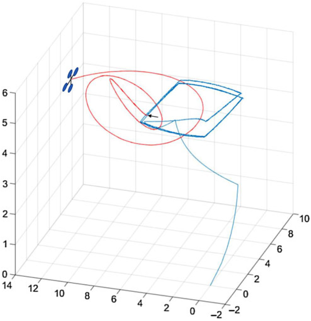
Figure 9. Simulation results show loss of control after failure of core 1, 2, 3 and 4 at t = 300 s. The time of failure is pointed with an arrow.
From the results presented, it is evident that a poor distribution can significantly degrade the reliability of the system, even resulting in worse reliability than a single core implementation.
8.0 CONCLUSION
In this work we have demonstrated a distributed implementation of a safety-critical system in an asymmetric multi-core platform with limited resources. The outcome of the experiment shows that consideration of criticality along with reliability of the individual subsystems is beneficial to minimising the probability of system failure (loss of control). Additionally, the results show that a strategic implementation of subsystems with different level of criticality on a shared hardware can improve the overall system reliability, where system level redundancy is not feasible due to the limitation of resources. Furthermore, such a distributed implementation is free from the complexities of multi-threading, while taking advantages of a multi-core architecture.
The proposed method is scalable to more cores and more subsystems, though the search time for the optimal distribution using a graph search grows rapidly. The work can also be extended to subsystem dependencies where dependent subsystems can be implemented together to reduce inter-core communications.
ACKNOWLEDGEMENTS
The authors would like to thank Henrik Schiøler from department of electronic systems, Aalborg University for his insightful comments and helpful discussion.
APPENDIX
The appendix describes the software implementation of the subsystems in four separate processors as shown in Fig. 7. Each subsystem is presented as a function call with the required arguments. The read and write functions in the pseudo code are methods to read and write memory mapped address spaces, denoted with parameters starting with ‘*’. Such memory mapped addresses are interfaced to external devices and on-chip communication network and can be accessed from the processor by reading or writing at the associated address.
Pseudo code for Processor 1

Pseudo code for Processor 2

Pseudo code for Processor 3

Pseudo code for Processor 4


