NOMENCLATURE
- CNSA
China National Space Administration
- DET
Direct-to-Earth Transmission
- ESA
European space agency
- GSFC
Goddard Space Flight Center
- ISRO
Indian Space Research Organisation
- JAXA
Japan Aerospace Exploration Agency
- KARI
Korea Aerospace Research Institute
- LiDAR
Light Detection And Ranging
- LROC
Lunar Reconnaissance Orbiter Camera
- MHP
Marius Hills Pit
- MIP
Mare Ingenii Pit
- MTP
Mare Tranquillitatis Pit
- NASA
National Aeronautics and Space Administration
- STRN
Surface Terrain Relative Navigation
- TRL
Technology Readiness Level
- UHF
Ultra High Frequency
- VLBI
Very-Long-Baseline Interferometry
1.0 INTRODUCTION
The exploration of the solar system is root-inspired by our imaginations which have been influenced by past science fiction writers. In his well-known classic, “The First Men in the Moon” (1901), H. G. Wells(Reference Wells1) first wrote about the existence of underground tunnels and caverns below the lunar surface. The following example passage from that novel is particularly pertinent:
“Presently we saw that the cavern before us opened on a hazy void. In another moment we had emerged upon a slanting gallery that projected into a vast circular space, a huge cylindrical pit running vertically up and down.”
Remarkably, over a century later, we now know that such lunar pits actually exist and Wells may have been prescient regarding their future sub-lunarean (or sub-selenean) exploration.
The Marius Hills Pit (MHP), also referred to as a ‘hole’ or ‘skylight’, was first discovered in 2009 by JAXA's Kayuga/Selene mission(Reference Haruyama2). It was subsequently imaged at higher resolution by NASA's Lunar Reconnaissance Orbiter Camera (LROC) along with several other similarly large pits(Reference Ashley3-Reference Wagner and Robinson5), Figs 1(a)–(c). The positions and approximate sizes of these enigmatic features are listed in Table 1. The following questions now need to be addressed:
1) How and when were these pits formed?
2) Do they represent openings to extensive subsurface voids such as lava tubes?
3) Are they of significant scientific interest?
4) Could they be utilised for future human lunar base infrastructure?
5) How should the preliminary sub-surface survey of these pits be prioritised?
6) What are the best concept solutions to perform preliminary sub-surface reconnaissance of these pits, especially to answer 2)?
7) What is the best preliminary exploration method to adopt in the near-term future?
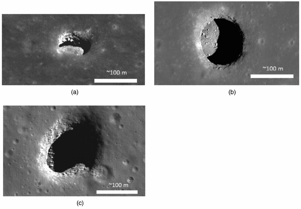
Figure 1. Known large lunar pits. (a) Marius Hills Pit (MHP) lateral view: note the stratified layers on the pit sidewalls and clear overhang showing subsurface lateral void. Credit: NASA/GSFC/Arizona State University. (b) Mare Tranquillitatis Pit (MTP) view from zenith: note the rubble on the pit floor/base. Credit: NASA/GSFC/Arizona State University. (c) Mare Ingenii Pit (MIP), view from zenith Credit: NASA/GSFC/Arizona State University.
Table 1 Parameters of lunar pits

None of these questions are fully answered in the following presentation, but collectively the partial answers offered may hopefully provide some additional impetus for a future mission-design study. What this work aims to establish is first that the exploration of these pits has a worthwhile rationale and second that such exploration could be achieved as a ‘piggyback’ (auxiliary payload) mission provided that any future lander lands at a nearby site.
2.0 RATIONALE FOR EXPLORATION
2.1 Lunar pit formation
Our knowledge of the sub-surface topologies and formation mechanisms of the lunar pits shown in Fig. 1(a)–(c) is currently based on poorly-constrained speculation. Oblique orbital views of both MHP (Fig. 1(a)) and MTP reveal that there are overhangs of up to ~20 m lateral extent near their floors(Reference Ashley3-Reference Wagner and Robinson5). However, it is currently unknown whether or not any of these overhang-voids extend somewhat further i.e. whether or not any offer accessible entrances to either a larger cavernous void or a lava tube(Reference Haruyama2,Reference Hong, Yi and Kim6) .
It is generally accepted(Reference Head7) that around 2.5-4 billion years ago, the Moon was volcanically active and there are many remaining relic features of that activity, including rilles and pyroclastic vents, etc. One possibility is that each of the lunar pits shown in Figs 1(a)–(c) formed during this active period through a combination of volcanic inflation, stopping and faulting processes – as has been used to explain the ‘Devil's Throat’ chamber in Hawaii(Reference Okuto and Martel8). If this viewpoint is correct, then each of the pits shown in Figs 1(a)–(c) are likely to be closed chambers, i.e. the images obtained to date reveal most of the sub-surface lateral void. However, this viewpoint could be challenged, e.g. the Devil's Throat is a rather irregular feature whereas the pits shown in Fig. 1(a) and (b) are essentially cylindrical. On first sight, they appear to be more similar to terrestrial sinkholes that are known to occur following underground acidic water erosion of Karst landscapes (e.g. the Sima Humboldt sinkhole located on the summit of the plateau of Sarisariñama tepui in Venezuela). Immediately it should be stated that this terrestrial sinkhole comparison may be entirely misleading since, unlike the Earth, the Moon was probably always devoid of any flowing water(Reference Hulme9). Nevertheless, the ancient lava flows that formed the lunar maria were far less viscous than typical contemporary terrestrial lavas flows(Reference Murase and McBirney10) and the predicted high effusion rates may have been capable of turbulent flows with enhanced thermal erosion(Reference Hulme9). Hence, a loose-analogy with terrestrial sinkhole formation involving sub-surface lava thermal erosion and drainage may have some validity.
Rilles(Reference Hulme9,Reference Hurwitz, Head and Hiesinger11) on the lunar surface are still not fully understood (despite the tour de force of the Apollo 15 mission), but it is now generally accepted that they were formed by ancient surface lava river-like flows and thermal erosion of the bedrock partly/wholly resulted in their current topography(Reference Hulme9). Lava tubes are formed by underground lava drainage flows and they have long been suspected to exist on the Moon(Reference Greeley12,Reference Coombs and Hawke13) . If non-collapsed lunar lava tubes did/do still exist, then it's possible that each pit may have been formed by ancient or recent tube roof collapses, possibly induced by lunar quakes or meteoritic impacts(Reference Martellato, Foing and Benkoff14). In other words, each pit entrance could be a collapse-skylight(Reference Haruyama2,Reference Hong, Yi and Kim6) leading to an extensive lava tube drainage network, instead of a closed chamber of limited extent(Reference Okuto and Martel8).
In the case of MHP (Fig. 1(a)), it is possible that the broad sinuous rille in which it occurs was eroded by a surface lava flow and another inner lava tube lies below the surface, similar to the (collapsed) inner-rille that appears in the Vallis Schröteri in the Aristarchus Plateau(Reference Garry, Bleacher and Warner15). What is puzzling, however, is that MHP only occurs within a rille, whereas the other two pits (Fig. 1(b) and (c)) have no nearby visible rilles, nor any other prominent volcanic features nearby. Furthermore, terrestrial lava tubes often have multiple collapse skylights running along the lava tube route(Reference Atkinson and Atkinson16), i.e. one might expect a train of skylights, or surface depressions marking former obliterated skylights. Assuming these pits were formed by collapse, then considerable rubble would be expected at the floor level (Figs 1(b) and (c)), but it is possible that some of this past collapse debris was carried-away by sub-surface lava flows.
On Earth, one of the largest known lava tube systems is ‘Undara’(Reference Atkinson and Atkinson16,Reference Stephenson17) which is ~250 km southwest of Cairns, Queensland, Australia. The largest Undara lava tube has an internal width of ~25 m and is ~1 km long and is easily accessible from the surface. Lunar lava tubes could easily be as large as Undara (or even larger), given the much lower lunar surface gravity(Reference Blair18) and they may be similarly accessible. However, as was explained above, the pits shown in Figs 1(a)–(c) may not be collapse skylights. An alternative possibility is that they are associated volcanic features possibly with drainage routes that lead to lava tubes at lower levels. It is worth noting that whereas the Devil's Throat(Reference Okuto and Martel8) is thought to be closed, the Wood Valley Pit Crater(Reference Favre19) also in Hawaii, permits access to a lower-level lava tube through a rubble pile (Fig. 2).
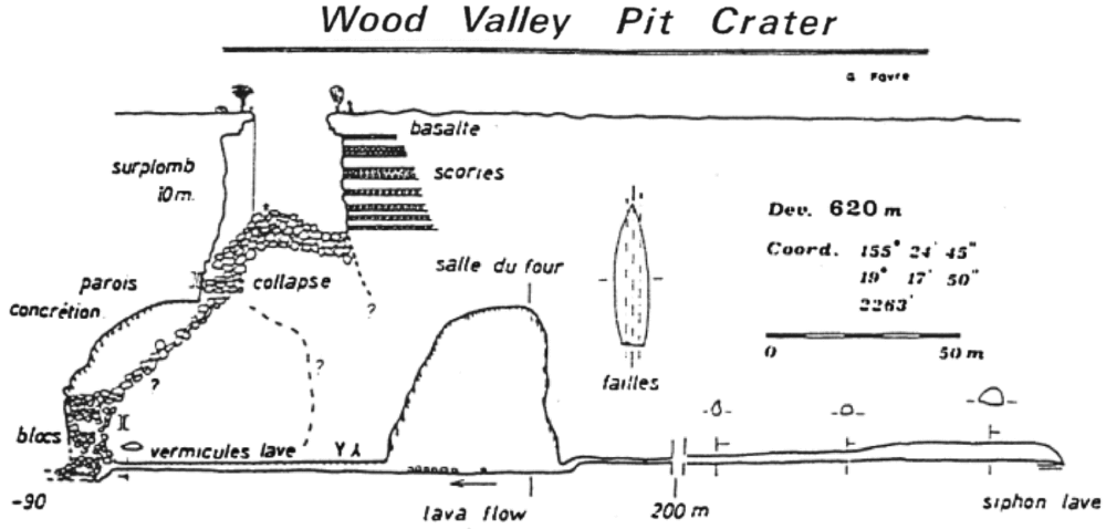
Figure 2. Wood Valley Pit Crater, Hawaii(Reference Favre19).
2.2 Broader scientific interest
In the near-future, any lunar pit reconnaissance mission will probably have to be justified on a broader scientific-priority basis than just curiosity concerning their topology and formation. Scientific interest in the pits (Figs 1(a)–(c)) would grow if they could be strongly linked to the goal of answering some of the fundamental questions concerned with the formation of our solar system, in particular the Moon's own formation and its early volcanic history(Reference Head7,Reference Crawford and Joy20) .
Access to lunar pits would permit sampling of ancient material, 40–100 m below the surface. Oblique views of the entrance necks of MHP and MTP indicate thin (~5 m) layering of past lava emplacements(Reference Robinson4). If these layers could be sampled, then they could yield trapped palaeoregoliths which would provide a valuable scientific record of solar activity up to ~4 Ga ago(Reference Crawford and Joy20). Admittedly, one difficulty with such an investigation would be extracting suitable rock specimens and the likely need for sample return to Earth in order in order to perform the necessary high-fidelity isotope measurements. Nevertheless, close-up images of the neck layers and the rubble pile on the pit floor would be a useful step in this regard.
Another related scientific question is whether, or not, any of these lunar pits contain volatiles (delivered by ancient bombardment), in particular water, in significant quantities(Reference Haruyama2,Reference Crawford21) . In order to retain icy-body deposited water(Reference Ong, Asphaug, Korycansk and Coker22) near the surface over long timescales (~1 Ga), the surface temperature needs to be maintained at less than ~100 K, a condition that only occurs in permanently shadowed regions near the poles(Reference Watson, Murray and Brown23,Reference Andreas24) . The average temperature expected in the permanent shadow regions of the pits shown in Fig. 1(a)–(c) is likely to be ~240 K (midway between the diurnal surface temperature extremes at the relevant latitudes). Consequently, it is most unlikely that water ice will be found lying exposed inside any open void within these pits. Despite this accepted situation, there still remains a possibility that other volatiles (e.g. sulphur) could remain trapped in secondary closed voids that might be accessed via drilling(Reference Cooper25). There is also a possibility that radiogenic gases (e.g. radon and helium) are currently being emitted from these pits – as is suspected with some other lunar features. In particular, in a geologically recent epoch, regolith appears to have been blown off by outgassing at the Ina ‘D Caldera’ in Lacus Felicitatus(Reference Schultz, Staid and Pieters26).
In summary, valid science-led objectives may be formulated to justify in situ pit exploration, but more effort is needed to define how exactly this fits with broader space (science) exploration priorities.
2.3 Utilisation for lunar base infrastructure
Past human settlement and the industrial development of several continents on the Earth was strongly influenced by engineering-geology factors(Reference Radbruch-Hall27). In particular, it is well known that caves provided Palaeolithic shelters and natural coastal harbours provided the focal points of many early settlements that later grew into major port cities. By analogy, it might be reasonably expected that the future settlement and industrial development of the Moon will correlate with the utilisation of any useful geological features and the prevailing technology constraints involved in their early exploitation.
As well as the over-arching Earth-Moon (cis-lunar) transportation difficulty, the main challenges facing early lunar base developmentReference Duke, Mendell, Roberts and Mendell(28,Reference Schrunk, Sharp, Bonnie, Cooper and Thangavelu29) , include the need for shielding from micro-meteoroid impacts(Reference Burke30), protection from solar radiation – especially during flares(Reference De Angelis31) and the desire for a benign thermal environment – avoiding extreme diurnal surface temperature variations (~95 K to ~390 K at the equator). Access to any accessible large sub-surface voids, such as lava tubes, might therefore offer significant benefits(Reference Horz and Mendell32-Reference Blamont34). Later this century, it is therefore possible that one or all of the pits (Figs 1(a)–(c)) could be utilised to support an early lunar base(s), possibly offering protection for (inflated) habitat modules and/or for propellant production and storage facilities for incoming and outgoing transports (see Appendix A). Consequently, early reconnaissance of any or all of these pits could offer a significant strategic advantage to any organisation (or nation) intent on eventual lunar industrialisation.
The possible existence of sub-surface volatiles is not just of scientific interest (Section 2.2), but closely links with the speculative lunar-base infrastructure opportunity. Indeed, the in situ production of liquid hydrogen and oxygen propellants from lunar extracted water appears to be a useful step to reduce long-term cis-lunar transport costs(Reference Spudis and Lavoie35). It should be noted, however, that in the event that no easily-extractable volatiles are found within (or nearby) any of the pits (Figs 1(a)–(c)), then it is also possible in the long term that volatile resources could be transported across the Moon from polar sites to a lunar base-port in much the same way as terrestrial resources are mined in remote-inhospitable locations and then transported (by road trucks and rails systems) to coastal cities or ports on Earth.
3.0 EXPLORATION CONCEPTS
3.1 Previously proposed methods
A variety of different schemes have already been proposed to explore lunar pits in situ:
i) Ximenes et al(Reference Ximenes, Elliot and Bannova36,Reference Ximenes37) have envisaged that future lunar explorers will abseil into these pits, and this would undoubtedly be the best way to learn much more about them, prior to their potential exploitation (Section 2.3).
ii) Whittaker(Reference Whittaker38), Yoshida(Reference Yoshida39) and Sauro et al(Reference Sauro, Bessone, Parmitano and Carnelli40) have advocated that the use of quasi-autonomous mobile (wheeled) rovers and tethered ancillary devices would be the best methods to gain access to and explore any potential lava tube. This approach appears to be well suited, provided that the landing site is with a few hundred metres of the pit and the terrain between the lander and the pit can be traversed in less than one lunar day. Possible concerns are that loose scree may be lying on the sloping faces around the pit, anchoring the rover may be a challenge and the wheeled descent unit might become lodged on the side walls of the pit.
iii) Instead of using rovers, Dorrington(Reference Dorrington41,Reference Dorrington42) and Robinson et al(Reference Robinson, Thanga, Wagner and Hernandez43) have proposed the use of micro-lander probes that would hover or land inside the pit. These concepts are discussed later (Section 3.4) and are the main focus of this work.
As well as in situ exploration, several different remote sensing methods have also been proposed to determine the size of the sub-surface voids. The current main difficulty with all the following remote methods is their limited spatial resolution capability, but they may prove advantageous as technology improves, particularly since it is possible to survey all the known pits from orbit and it is not necessary to select one priority target.
i) Use of a gravimetric method. Ground-based gravimetric survey has been proven feasible to locate terrestrial lava tubes(Reference Brown44); however, to date, the resolution capability of lunar orbital surveys has not been sufficient to confidently detect voids of ~100 m(Reference Chappaz, Sood, Melosh and Howell45-Reference Carroll47).
ii) Use of a ground penetrating radar (Reference Rowell, Pidlisecky, Irving and Ferguson48). To obtain sufficient resolution to confirm void dimensions, this technique would probably require a surface rover, as demonstrated by Zhao et al(Reference Zhao49). Orbital radar signatures will have limited resolution, but it is worth noting that Haruyama et al(Reference Haruyama50) have recently claimed the radar sounder aboard Kayuga/Selene has detected a lava tube running a few tens of kilometres westward from MHP.
iii) Use of a thermal signature method. This has been proposed for the identification of pits on Mars(Reference Cushing and Titus51), but is unlikely to be viable for the near-vacuum conditions of the Moon.
iv) Use of a reflected sunlight method. To deduce the existence of lateral walls, this may be useful for some Martian pits that have conical collapse features(Reference Jung, Seon, Cho and Yi52).
v) Use of a magnetic method. At least one terrestrial lava tube is known to display a magnetic contrast to surrounding host rock and can be detected from the surface(Reference Hay, Brown, Samson and Ellery53). Consequently, it may be possible to use magnetometer fitted rovers to detect sub-surface lunar lava tubes.
vi) Use of pulsed laser back-scattering and detecting corresponding reflection time delays of order 10−8 s from voids beyond line-of-sight, as has been recently proposed in the NASA ‘PERISCOPE’ project(Reference Nosanov and Hall54,Reference Nosanov, Velten, Mitchell and arora55) . This appears to be one of the most promising future orbital detection methods. Although this technology is currently still at TRL ~3, significant advances may occur before 2025.
3.2 General considerations for preliminary in situ exploration
Before employing advanced exploration methods, it could be argued that what is first required is a minimum-cost reconnaissance mission(s) simply to determine whether or not at least one of these pits (Figs 1(a)–(c)) leads to a more extensive void. Furthermore, such a mission must have low technical risk, in the sense that there should be little or no emphasis on developing new technology i.e. the primary focus of the mission should be to obtain lateral images, or LiDAR scans, from near-floor-level of one (or more) pit(s) in an expedient manner. In other words, the first reconnaissance mission should employ a minimum mass probe(s) using existing technology with TRL > 6. The remainder of this article aims to set-out some promising architectures for such a preliminary (non-advanced) reconnaissance mission.
The most desirable mission architecture to obtain preliminary lateral images from near-floor level of any of the pits (Figs 1(a)–(c)) is one which offers an adequate data return at a minimum mission cost, and also one that offers sufficient technical reliability. Arguably, the largest technical risks are safely landing on the Moon and traversing across its surface (trying to avoid surface boulder, rubble and dust hazards) especially for long durations requiring power through the lunar night. A short endurance mission (lasting a few Earth days at most), during the lunar day, involving just one landing probably offers the lowest risk.
Assuming that ~100 Mbytes of pit topography data is sufficient, then data transmission would require just a few minutes at most. Direct-to-Earth Transmission (DET) of this data might be expected to offer the simplest, lowest-cost approach, but is only possible in one particular case. When operating close to the floor of the MHP (Fig. 1(a)) it is not possible to view the Earth. At certain lunar liberation conditions, a region on the east side of MTP (Fig. 1(c)) does permit DET and the surface of that region is also relatively rubble-free.
Assuming the primary imaging system for a preliminary mission is likely to have a mass of ~1–5 kg one might reasonably expect that a micro-sized spacecraft with a gross mass ~10–20 kg could be employed. A plethora of different conceptual options may be envisaged ranging from the use of propulsive landers(Reference Dorrington41-Reference Robinson, Thanga, Wagner and Hernandez43) or hoppers (e.g.)(Reference Huber56-Reference Leitner59), wheeled rovers(Reference Whittaker38-Reference Sauro, Bessone, Parmitano and Carnelli40), or even line-thrower-type rockets (of Congreve heritage) and trebuchet throwers. Instead of assessing all these options, this article simply presumes the use of a propulsive microprobe that flies or hops(Reference Alibay60,Reference Middleton, Paschall and Cohanim61) from a prescribed landing site to the interior of the targeted pit. This propulsive flight approach arguably has a strong technical heritage and is a likely concept solution for the presumed preliminary reconnaissance mission.
3.3 Pit selection for the first exploration mission
The selection of the best-choice pit for the first reconnaissance is a matter of debate, since each has unique advantages and disadvantages from both scientific and technical viewpoints (Table 2).
Table 2 Selection of pit for first reconnaissance
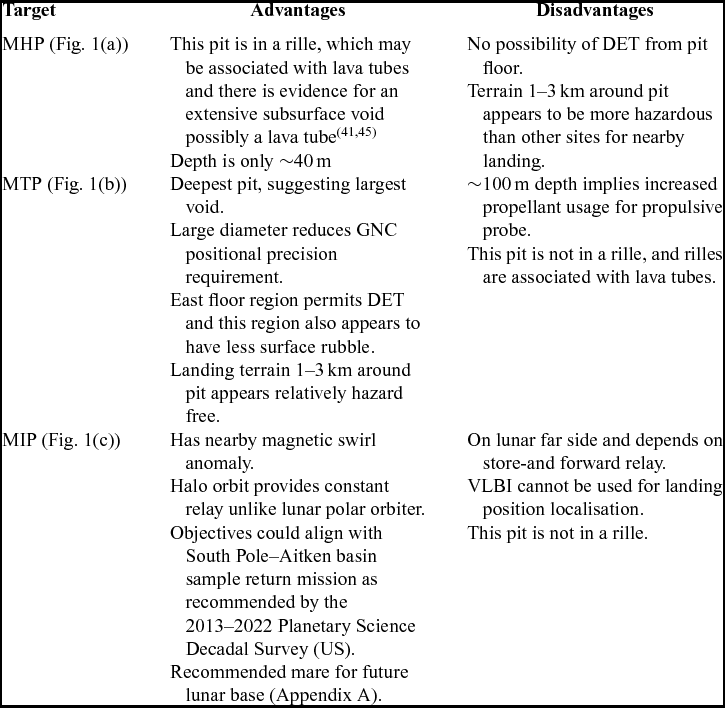
One compelling reason to select MHP (Fig. 1(a)) as the primary target is that it is the only feature associated with a sinuous rille and arguably it is most likely to provide access to a lava tube(Reference Haruyama50). However, from an overall science perspective MIP (Fig. 1(c)) and the region around it may be considered a more attractive scientific target e.g. since it has a magnetic ‘swirl’ anomaly(Reference Blewett62) nearby (Fig. 3), and it lies within northern part of the South-Pole Aitken basin, which is a target of current priority interest within the lunar scientific community (Section 5.5). Indeed, it may be possible to combine the pit reconnaissance mission with a low-altitude magnetometer survey of this swirl feature and/or with a sample return mission. The disadvantage of selecting MIP is that it lies on the lunar far side, hence a store-and-forward spacecraft is a necessity, but in this case, it may be possible to utilise a communications relay in lunar halo orbit(Reference Farquhar63) which would provide uninterrupted data relay from the surface back to Earth (unlike a conventional lunar polar orbit).

Figure 3. Location of MIP (arrow) near lunar swirl feature ‘S’ in Thomson-M crater. Image width 160 km. Credit: NASA/Goddard/Arizona State University.
As well as MHP/MTP/MIP, it should also be stressed that some other smaller pit or even perhaps a lunar-impact melt-pit feature(Reference Hong, Yi and Kim6,Reference Wagner, Robinson and Ashley64,Reference Ashley, Robinson, Wagner and Hawke65) may eventually be selected for its joint scientific and habitability potential, but hopefully much of the following discussion still remains valid.
3.4 Pit interior survey flight concepts
Several different pit reconnaissance strategy options are briefly considered below:
i) Landing directly from lunar descent into the pit (‘hole-in-one’).
ii) Landing nearby and then a probe hops to the pit and lands on pit floor.
iii) Landing nearby and then a probe hops to the pit, but instead of landing flies in out of the pit.
iv) Landing nearby and then a probe hops to the pit, remains hovering above and lowers a tethered image unit.
At first sight, the first option appears to be the simplest and best. In particular, it would be possible to land within the DET region of MTP in order to acquire the required images (after landing) and then use DET as has been proposed for the ‘ARNE’ mission(Reference Yoshida39). However, this ‘hole-in-one’ scenario requires development of an ultra-precision landing technique that may be beyond current technical capability (Appendix B). If instead it is assumed that, after descent from lunar orbit, the 95% probability landing-position dispersion ellipse semi-major axis is ~2.5 km, then the aforementioned ‘hole-in-one’ strategy is no longer viable.
In the second option, when the focus of landing dispersion ellipse is centred on the pit, the main spacecraft is expected to soft-land up to ~2.5 km from the pit entrance (Fig. 4). A probe, piggyback mounted on the main lander, is then used to perform the required hop or hover translation. Over this relatively short hop distance, the pit entrance could be reached using inertial navigation, possibly in conjunction with the terrain proximity altitude sensing using LiDAR (Appendix B). Once the probe is known to be hovering above the pit entrance, it would then be commanded to descend into the pit at a prescribed descent rate of ~5 m/s i.e. for MHP, it would take ~8 s to reach the pit floor. During this descent, images of the sidewalls could be obtained. The primary lateral images required of a possible void would then be quickly obtained whilst hovering ~5 m above the pit floor level, or they could be acquired after landing has been attempted. If the probe is within the DET region of MTP (Section 3.2), then the probe could transmit data directly. Alternatively (and necessarily the case of MHP), the probe could transmit data from the pit floor when the store-and-forward relay is overhead.

Figure 4. Main spacecraft lands at lunar dawn some distance from a pit and the exact landing position is established using VLBI (top). A piggyback probe is then launched, hops and lands on the pit's rubble floor (bottom).
The third option (Fig. 5) arguably reduces mission risk by avoiding a probe landing in the selected pit. After acquiring lateral images during hover at ~5 m above floor level, the probe would re-ascend at about 5 m/s (whilst re-imaging the pit sidewalls). Once back above the horizon and in direct view of the lander, or the store-and-forward orbiter, the probe could transmit the stored images via a short-range UHF link. However, one criticism of this hop-in-and-out strategy is that the pit lateral images would have to be acquired whilst the probe is held in thrusting hover at ~5 m above floor level which could result in some surface regolith ejection and lateral image obscuration(Reference Wagner66), as well as possible adverse vibration issues.
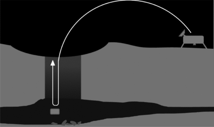
Figure 5. Instead of landing on the hazardous pit floor, the probe acquires the required images while hovering ~5 m above the pit floor and then re-ascends in order to transmit those images back to the lander for relay.
The forth option (Fig. 6) involves splitting the probe into two major subsystems: a probe bus that would remain hovering above the pit at an altitude that retains direct line-of-sight with the lander (as well as offering the possibility of DET in the case of MTP and MHP), and an imaging unit that would be freely-lowered using a spooled tether until it is ~5 m from the pit base. This arrangement avoids the possibility of regolith disturbance and possible adverse dust effects(Reference Wagner66,Reference Metzger, Li, Immer and Lane67) . Provided that the tether can be freely spooled-out (solely using lunar gravity) at ~1.6 ms–2, it would require just ~7 s to reach the MHP base, and the images could then be sent via fibre-optic cable, or by UHF/bluetooth link, from the imaging unit to the probe. Compared with the third option, the total probe flight time is reduced (which reduces the propellant mass, compensating to some extent for the mass of tether and spool). It could also be argued that the recent successful deployment of the Mars Science Laboratory (MSL) ‘Curiosity’(Reference Steltzner68) indicates that such tethered spool-out is viable at sufficiently low technical risk (TRL > 6), although it should also be stressed that the MSL bridle length was ~8 m, whereas the exploration of MHP would require a tether of at least 40 m length.
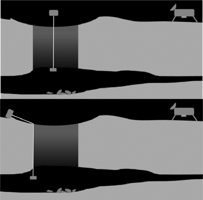
Figure 6. Alternative tether scheme: The probe bus remains hovering above surface level and a tethered imaging (LiDAR) unit is freely spooled to near-floor level (top). The probe could then soft-land to one side of the pit leaving the imaging unit hanging in the pit to acquire secondary science data (bottom).
3.5 Probe configuration, size and mass
A concept schematic of a possible probe configuration suitable for the tether scheme (Fig. 6) is shown in Fig. 7. The key technical challenge is the realisation of a micro-propulsion system capable of achieving a probe thrust-to-weight ratio of ~2, in order to perform a short-range hop-translation from the lander and to enter into the pit (Appendix C). A tentative mass breakdown is presented in Table 3, although this is sensitive to the uncertain masses of several sub-systems and components that have not yet been fully defined.
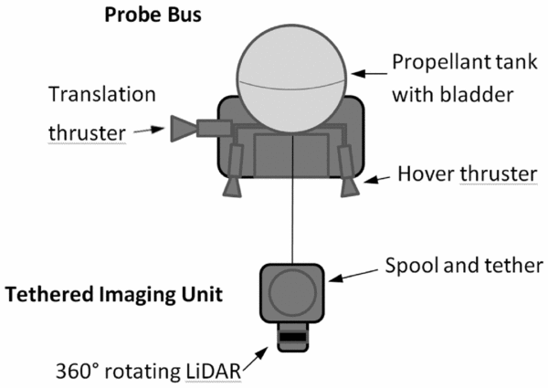
Figure 7. Schematic of possible pit microprobe with tethered imaging unit (not to scale).
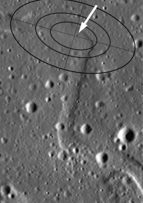
Figure 8. View of Sinuous Rille A and area near MHP Credit: NASA/GSFC/Arizona State University.
Note: the white arrow indicates the actual position of MHP and the ellipses added to this image represent the typical landing positional dispersion after descent from a ~20° inclination lunar orbit with various undefined probabilities (approximate scale only, but illustrating that dispersion-distances far exceed pit diameter).
Table 3 Tentative microprobe mass breakdown/kg
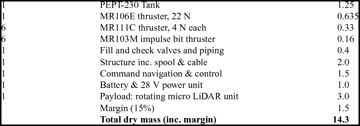
A hydrazine (N2H4) monopropellant system would be strong contender for probe propulsion (Appendix D). One of the smallest space-qualified N2H4 tanks is the CNES PEPT-230: a 230 mm diameter spherical titanium alloy (6AL-4V) tank with a rubber diaphragm (4:1 expulsion), a mass of 1.25 kg and capable of holding up to 4.5 kg of N2H4 at a maximum pressure of 22 bars(Reference Hasan69). This capacity is more than sufficient for the propellant fraction (~0.2) required for a non-optimal 2.5-km traverse with a 100-second hover over the pit, and with 0.5 km range margin (Appendices C and D), resulting in gross probe mass of ~17 kg. A combination of Aerojet (or any competitive supplier, off-the-shelf) N2H4 thrusters could be used, employed for attitude control, vertical launch and horizontal translation (with one 22 N thruster used for both acceleration and braking after 180° yaw rotation). Alternatively, cold gas thrusters could be used for fine attitude and position control during hover. Power (28 V, ~4 amp peak) for thruster operation, tank heating, command, communications and payload would be provided by a ~1 kg primary cell battery and power unit. Structural mass is estimated to be ~2 kg, including the unpowered spool unit and tether. Assuming that the primary payload is a 360° LiDAR e.g. a space-hardened version of a Velodyne micro-unit(70), or a reduced mass version of the Neptec rotating unit(71), the payload mass would be ~3 kg. In summary, a probe mass target of ~14 kg (dry) appears to be feasible, but is sensitive to component mass changes. Reduction in dry mass (especially thruster mass) appears to the key design issue.
3.6 Possible opportunities for lunar piggybacking
The low-cost system architecture recommended above to explore one of the lunar pits shown in Figs 1(a)–(c), necessarily assumes a sufficiently large lander will target the appropriate lunar site, and furthermore that a probe of ~17 kg gross mass will be permitted to piggyback on such a future lander, which might be constrained to a total payload of ~40 kg Reference Carpenter, Fisackerle, De Rosa and Houdou(72). Table 4 lists lunar lander missions currently planned or proposed over the next decade or so. Four of the proposed missions target the South Pole, reflecting the strong current scientific interest in finding possible volatiles in permanently shadowed regions.
If approved, then JAXA's ‘Smart Lander for Investigating Moon’ (SLIM) mission(Reference Sakai73) might elect to target the region near MHP, but since SLIM is deemed a technology demonstrator, it is likely to be payload constrained (or not offer any scientific payload), therefore it is unlikely to offer any piggyback ride. The ‘Farside’ proposal(Reference Wieczorek74,Reference Mimoun75) for a mission to the South Pole-Aitken basin (which includes Mare Ingenii) might be resubmitted to ESA and might therefore still offer a possible opportunity to visit MIP around 2025. The planned landers of Roscosmos, ISRO and CNSA are already well defined, but a lunar mission planned by KARI(Reference Moon76) still appears to be in the conceptual phase and may be another piggyback opportunity. Alternatively, one of a number of commercial missions, or publicly funded ventures, might offer a suitable piggyback opportunity, e.g. Moon Express. Of course, all these future missions are subject to possible revision.
4.0 DISCUSSION
The following discussion provides a brief summary of the feedback the above concept received from various sources (see Acknowledgements) after it was first presented(Reference Dorrington41,Reference Dorrington42) .
A major strength of a lunar pit reconnaissance mission is that it is driven by a simple, easy-to-convey public outreach question: do large accessible underground caves or lava tubes exist on the Moon? Crowdfunding is a current emerging opportunity that may result in the realisation of such popular exploration objective missions e.g. as witnessed by recent funding achievements for ‘Lunar Mission One’(Reference Joy77), (Table 4).
Table 4 Planned/proposed lunar lander missions
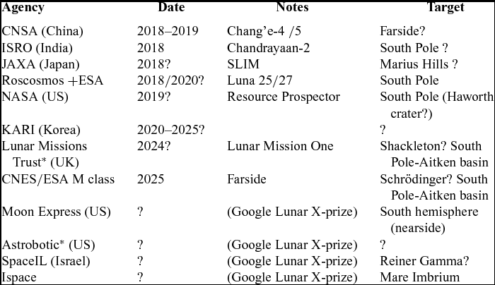
*Teamed together Oct. 2015.
A major weakness of a lunar pit reconnaissance mission is the likeliness of any piggyback opportunity in the near future (Section 3.6). One way to circumvent this problem is to propose a dedicated pit exploration mission. Such a detected mission might be integrated with local surface science or with a sample return mission that would substantially modify the architecture proposed above.
Aside from other planetary exploration priorities, there are many other lunar targets that may be preferentially selected on the basis of the scientific data return that they offer with regard to current knowledge gaps regarding lunar formation history. The discovery of large lunar pits (Figs 1(a)–(c)) is of interest to notable lunar science experts(Reference Robinson78), but they may still be regarded as a non-essential curiosity by the wider planetary science community, e.g. there is no mention of lunar pits in a 2011 US Decadal Survey(79). This situation would probably change if yet another similar pit (or melt impact cave) was found in a permanently shadowed region near the South Pole. Such a feature would probably be regarded with much higher scientific priority because of the potential for discovery of volatiles (in particular, water ice).
Another major difficulty is that, although the technical risk of a pit reconnaissance mission could be minimised to acceptable levels, there is a significant likelihood that the pit that is chosen for first reconnaissance mission could be found to be closed: i.e. it may not offer access to any significant void space that cannot already be detected from orbital images. Consequently, it might be argued that instead of opting for an in situ probe mission that necessarily preselects only one pit for budgetary reasons, it may be better to employ a lunar orbiter and try to detect extensive pit voids and/or lava tubes remotely (Section 3.1).
In terms on long-term human exploration of the Moon, there remains ambiguity as to exactly how MHP/MTP/MIP could actually be utilised assuming each is essentially closed. Ashley et al(Reference Ashley, Robinson, Wagner and Hawke65) boldly declare that it is a ‘common-sense expedient’ to utilise these pits, but the actual development details of any early lunar base build-up involving these features (advantageously) have yet to be fully described. The current consensus is that an early lunar base is likely to be based near the South Pole (Appendix A).
As with the Moon, similar considerations apply to Martian pit(Reference Cushing80) exploration. One main difference, however, is the existence of a tenuous Martian atmosphere (density ~0.02 kgm–3 at surface level) that permits alternative concept solutions – as well as introducing different challenges(Reference Dorrington81). The key point is that exploration of Martian pits could be achieved using a similar concept to the one advocated here, namely the use of a short range propulsive hopper that lowers a tethered imaging unit (Fig. 6).
5.0 CONCLUSIONS
The discovery of large lunar pits (Figs 1(a)–(c)) may represent a significant game-changer for future lunar exploration. In the near-future, it is possible that a major space agency, or private (non-profit) organisation may elect to send a future lander to either Marius Hills in Oceanus Procellarum (not yet visited), or to Mare Tranquillitatis (visited by Apollo 11, etc.), or to Mare Ingenii (part of the South Pole-Aitken basin, not yet visited). If that occurs, then there would arise an opportunity for an auxiliary reconnaissance mission using a piggyback microprobe to hop to one of the pits. Such a probe (with a dry mass of ~10–20 kg) could feasibly perform a propulsive-controlled, short-hop flight to either of the pits in these locations. This auxiliary mission would not only provide enhanced public outreach, but it would also result in confirmation of the extent and internal topology of sub-surface lunar voids and help to constrain plausible formation mechanisms. The possible discovery of large cavernous voids or lava tubes is likely to have a significant influence on future (human/robotic) lunar exploration, and might offer strategic advantages in terms of early lunar base set-up and long-term lunar exploitation.
The technology development effort for such a preliminary exploration probe appears to be relatively modest, provided a soft lander is placed within ~10 km of one of the pits. Such a probe could employ well-established guidance and control techniques as well as well-proven propulsion technology, and consequently could probably be achieved as part of a realistic near-term mission. However, there are several unresolved issues that may dissuade any agency (or private organisation) from targeting any lunar pit (see previous section) and many of the viewpoints expressed in this work require reinforcement. It is therefore recommended that the following supporting studies should be undertaken:
1) A more comprehensive study to determine how a pit reconnaissance mission could be justified in terms of relative scientific value, bearing in mind scientific interest in other potential lunar targets, and the current ranking of top-level scientific priorities(Reference Crawford and Joy20,Reference Robinson78,79) .
2) A preliminary design study of a pit probe, including a more detailed comparison of the exploration strategies introduced in this article and elsewhere.
3) A comparative evaluation of all other lava-tube detection methods and remote exploration techniques not adequately considered in this article.
4) A study to evaluate which of the pits shown in Figs 1(a)–(c), or any alternative impact melt craters should be given priority for the first sub-lunarean (or sub-selenean) void mission.
5) A study to evaluate exactly how any of the pits (Figs 1(a)–(c)), could feasibly be utilised to reduce early lunar base set-up costs, dependent on the actual void size conjectured. In this evaluation, possible field trials using an Earth-based analog-feature e.g. the Undara lava tubes(Reference Atkinson and Atkinson16,Reference Stephenson17) , would be useful.
6) A study to evaluate how the long-term infrastructure of a future ‘Moon Village’(Reference Woerner and Foing82) would be influenced by selecting one or more of the pits (Fig. 1(a)–(c)) as the focal point of early lunar-base location(s), bearing in mind that volatile extraction might be constrained to the lunar poles.
Possible synergies and technology convergences associated with Martian pit exploration(Reference Cushing80,Reference Dorrington81) need to be considered in the previous recommended tasks. Indeed, it is possible that the exploration of Martian pits may precede the exploration of lunar ones.
ACKNOWLEDGEMENTS
The probe concept described herein was first proposed at the Low Cost Planetary Mission Conference (LCPM-11) in Berlin, June 2015 and received some feedback from attending delegates. The concept was revised and re-presented at the Asia-Pacific International Symposium on Aerospace (APISAT) in Cairns, Australia, 2015. The resulting article was subsequently selected by a joint APISAT and the Royal Aeronautical Society committee for publication in this journal and I wish to thank the committee for thereby encouraging this submission. I would also like to thank the additional anonymous referees assigned by the journal for their useful critical comments that helped to further improve the original APISAT paper, although none of the aforementioned are responsible for any remaining ambiguities, mistakes and/or misconceptions.
APPENDIX A: SPECULATION OF LUNAR BASE BUILD-UP
The requirements for lunar habitation and human exploration are demanding(Reference Carpenter, Fisackerly and Espinasse83). Many scenarios for lunar base build-up(Reference Duke, Mendell, Roberts and Mendell28) assume habitation modules (constrained to launcher payload bay dimensions) are delivered to the surface and connected by cranes, etc. The assembled modules are usually depicted with several metres of regolith covering them in order to protect them from cosmic-particle and micrometeorite penetration(Reference Burke30,Reference Carpenter, Fisackerly and Espinasse83) . However, this build-up scenario requires a significant lunar-surface logistics effort, e.g. some kind of bulldozer for moving tonnes of regolith. There are also many unresolved issues such as the possibility of abrasive lunar dust entering air locks, etc.
The interior of a lava tube would offer a natural safe haven from solar radiation (flares) and micrometeorite bombardment(Reference Burke30-Reference Blamont34). It would also be comparatively clean insomuch as it would not have substantial regolith dust, and its walls are likely to be smooth basalt lava surfaces. Relatively lightweight inflated habitats might therefore be used inside the tube for temporary habitation. Admittedly, a different logistical challenge arises: in order to get crew and equipment down through the pit entrance, a crane or elevator system is needed and/or it would be necessary to create a landing pad on the pit floor.
In the long term, it would be possible to block the lava tube entrance with some kind of plug, in order to permit a sub-surface breathable atmosphere environment pressurised at up to ~1 bar. Once the tube walls are insulated, the power requirement to maintain a steady working temperature of ~300 K would be modest. Solar photovoltaic arrays could be sited nearby on the surface and their power transmitted to the tube via cable. If the tube is several tens of kilometres long(Reference Chappaz, Sood, Melosh and Howell45), then the habitable section could be extended gradually over a period of time, eventually permitting a continuously occupied lunar base with several hundred occupants.
The siting of any early lunar base (or bases) will involve a difficult choice between logistical, exploration and science-objective preferences. In this respect, it is worth noting that Staehle et al(Reference Staehle, Burke, Dowling, Spudes, Lewis, Matthews and Guerrieri84) advocate various (non-polar) sites including Mare Ingenii and Aristarchus which has a small pit(Reference Hong, Yi and Kim6). Most lunar-base advocates suggest that the first habited base must be sited near the South Pole -in order access permanent-shadow craters suspected to contain water ice and to take advantage of near-permanent solar illumination. An alternative possible scenario is that the South Pole resource extraction facility is largely operated autonomously, whereas human habitation modules are sited within the safe protection of a lava tube(s). With such an extended ‘Moon Village’ the need for lunar surface – surface transportation follows.
APPENDIX B: GUIDANCE, NAVIGATION AND CONTROL
Selection of pit reconnaissance strategies largely hinges on the (perceived) TRL of the descent Guidance, Navigation and Control (GN&C) technology that is employed. Apollo Lunar Modules (1969 – 1972) depended on inertial navigation sensors, but it is well known that lunar pilots resorted to visual cues and manual control to avoid hazardous terrain when in close proximity to the lunar surface (less than ~100 m altitude). The predicted 90% landing dispersion ellipse for Apollo 12 was ± ~2 km down-range, ~1 km cross-range(Reference Bennett85). For near-future robotic landers, inertial guidance is likely to be supplemented by Surface Terrain Relative Navigation (STRN) that would involve scanning the surface topography during the final lunar descent phases, when the lander is less than ~100 km from its target(Reference Paschall86). In order to establish and correct position and heading during descent, the scanned topography map would be periodically correlated against the known map, which has substantially improved after the surveys of LROC. Despite this improvement, however, it seems likely that the unquantified landing dispersion probability ellipses could still far exceed the size of the pit entrance (Fig. 8).
Analog tests on Earth using STRN for an aircraft flying at ~60 m/s have achieved projected positional landing errors of less than 90 m(Reference Johnston and Ivanov87). Since this still exceeds the width of MHP (~65 m), descent of a lander from lunar orbit directly into a pit appears to be overly demanding with current STRN capability. On the other hand, it could be countered that MTP/MHP/MIP are such distinctive physical features that they could offer much improved positional localisation. Furthermore, it should be noted that any successful propulsive pit descent would necessarily require fine positional control (i.e. less than ~10 m lateral error).
One main advantage of employing a separate lander plus probe and landing near any pit (as opposed to descending directly from orbit into one) is that the exact landing position and orientation of the lander could be acquired, e.g. using Very Long Baseline Interferometry (VLBI) some hours after landing. After the precise heading to and range from the target pit are established, then telemetry could be sent in order to command the probe to perform the required ballistic hop or lateral hover translation (Appendix C). This staged landing strategy also minimises the lander hover time and therefore reduces propellant mass. Current lunar STRN efforts primarily aim to increase landing precision, but that necessarily implies that more propulsive control inputs are required in order to steer any lander to the desired target, i.e. adoption of STRN typically increases the descent propellant mass fraction.
In summary, a more detailed and rigorous GN&C study is needed to establish which strategy actually represents the best near-term option for pit reconnaissance (noting that for long-term lunar development, a lunar satellite global positioning system, like Earth-based GPS, might be deployed).
APPENDIX C: SIMPLE PROPULSIVE ANALYSIS OF LUNAR HOVER AND TRANSLATION
To achieve stationary propulsive hover, the vertical thrust must equal the probe total weight, mg luna, where g luna≅ 1.62 N/kg. The thrust is the product of the hover propulsion-system-specific impulse and the propellant mass-flow-rate, ![]() $F = {g_{{\rm{Earth}}}}{I_{sp}}\dot{m}$, where the specific impulse is defined with units of seconds based on the gravitational acceleration at the Earth's surface g Earth≅ 9.81 N/kg. Hence, after integration, the hover time is:
$F = {g_{{\rm{Earth}}}}{I_{sp}}\dot{m}$, where the specific impulse is defined with units of seconds based on the gravitational acceleration at the Earth's surface g Earth≅ 9.81 N/kg. Hence, after integration, the hover time is:
where m 0 is the gross-initial mass and m prop is the propellant mass consumed. The equivalent delta-V for the same propellant mass consumption and specific impulse is simply g lunat hover.
For a near-horizontal hover-traverse, various dynamic assumptions may be made, but the simplest case is one in which the spacecraft undergoes constant (positive) lateral acceleration αg luna at near-constant altitude for a period of tacc seconds, followed by constant (negative) lateral deceleration, − αg luna, for the same period, bringing the spacecraft back to rest at the same altitude. The distance covered during the acceleration phase is simply ![]() $\frac{{{\alpha g_{{\rm{luna}}}}t_{acc}^2}}{2}$ and the total distance covered before returning back to rest is, R hover = αg lunat 2acc. Using the same propulsion system for hover and translation and assuming the translation velocity always remains much less than the orbital velocity, it follows that,
$\frac{{{\alpha g_{{\rm{luna}}}}t_{acc}^2}}{2}$ and the total distance covered before returning back to rest is, R hover = αg lunat 2acc. Using the same propulsion system for hover and translation and assuming the translation velocity always remains much less than the orbital velocity, it follows that, ![]() ${g_{{\rm{Earth}}}}{I_{sp}}\dot{m} = m{g_{{\rm{luna}}}}( {1 + \alpha})$ and integrating over the total time period:
${g_{{\rm{Earth}}}}{I_{sp}}\dot{m} = m{g_{{\rm{luna}}}}( {1 + \alpha})$ and integrating over the total time period:
 $$\begin{equation}
2{t_{acc}} = \sqrt {\frac{{4{R_{{\rm{hover}}}}}}{{{\alpha g_{{\rm{luna}}}}\ }}} = \left[ {\frac{{{g_{{\rm{Earth}}}}}}{{{g_{{\rm{luna}}}}\left( {1 + \alpha} \right)}}} \right]{I_{sp}}ln\left[ {\frac{{{m_0}}}{{{m_0} - {m_{{\rm{prop}}}}}}} \right]
\end{equation}$$
For this non-optimal manoeuvre, the propellant mass is minimised for a given range when ![]() $\sqrt {} \alpha /( {1 + \alpha } )$ is maximised, i.e. when α = 1. In this particular case, the propellant mass is given by:
$\sqrt {} \alpha /( {1 + \alpha } )$ is maximised, i.e. when α = 1. In this particular case, the propellant mass is given by:
where λ = g 2EarthIsp 2/(16g luna) and the equivalent delta-V for the same propellant mass consumption and specific impulse is simply:
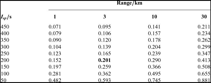
Some numerical examples of the calculated propellant mass fraction, m prop/m 0 values, using Equations (1) and (3) are given Tables 5 and 6. These demonstrate that near-constant altitude hover-translations of up to ~30 km can be achieved with relatively modest specific impulse propulsion systems. For ultra-short-range missions, less than ~3 km including a pre-landing stationary hover (margin) of ~100 s, may be achieved with the relatively low propellant mass fractions compared to typical rocket propulsive-stage values.
Table 5 Propellant fractions for translation alone
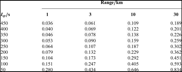
Table 6 Propellant fractions for combined translation and 100s hover
It should be noted that even lower propellant fractions could be achieved using ballistic hops. The non-optimum translation described by Equation (4) requires twice the delta-V needed to bring about a simple non-thrusting ballistic trajectory (employing instantaneous impulse burns at an angle of 45° at the start and end of flight) over the same range. In this case, using a flat Moon approximation (again assuming flight velocities remain much lower than orbital velocity), the lateral horizontal velocity is simply Vx = V 0/√2, where V 0 is the initial velocity after the impulse burn, and the vertical velocity is ![]() ${V_y} = \frac{{{V_0}}}{{\sqrt 2 }} - \ t{g_{{\rm{luna}}}}$. The maximum altitude is reached when g lunat 1 = V 0/√2 and the maximum range achieved, at t = 2t 1, for the complete symmetric lob is simply R lob = V 20/g luna. Therefore, the total delta-V required to accelerate and decelerate back to rest is:
${V_y} = \frac{{{V_0}}}{{\sqrt 2 }} - \ t{g_{{\rm{luna}}}}$. The maximum altitude is reached when g lunat 1 = V 0/√2 and the maximum range achieved, at t = 2t 1, for the complete symmetric lob is simply R lob = V 20/g luna. Therefore, the total delta-V required to accelerate and decelerate back to rest is:
For the same range, ballistic lobs therefore have about half the delta-V requirement of fixed altitude translations. Cheng and Conrad(Reference Cheng and Conrad88) predict that the optimum thrusting trajectory is a slope-constrained brachistochrone, but the resulting optimal propellant mass fractions are similar to the simple ballistic case above.
In reality, the propellant budget for mid-flight course corrections and attitude control must also be considered; however, it is reasonable to assume that these extra demands do not dominate.
APPENDIX D: SELECTION OF PROPULSION SYSTEM
The effective delta-V requirement for a lunar ballistic hop of ~3 km is ~140 m/s (Appendix C). The use of inert cold gas (e.g. nitrogen gas with specific impulse ~70 s) alone appears to be marginal for hop-translation ranges above ~ 1 km, but might be considered for hover phases less than ~100 s. For microsatellites, electrical propulsion systems (e.g. resistojets) are viable for station-keeping (etc.), since the required thrust levels are relatively low. For lunar hover translation, thrust levels in excess of ~20 N are required for a probe of ~17 kg gross mass, which is relatively high compared to previous microsatellite/CubeSat thrust levels(Reference Mueller89-Reference Carpenter91); hence, the adoption of chemical propulsion systems appears to be necessary. For microsatellites, monopropellant systems are often employed instead of bipropellant systems, since although the latter offer higher specific impulse, they are more complex (having nearly twice the number of components) and typically have higher dry mass for a given thrust level. Indeed, for a combined lunar hover translation of ~3 km and hover of less than ~100 s, the specific impulse of well-proven hydrazine (N2H4) monopropellant systems (~200–250 s) appears to be more than adequate (Tables 5 and 6). The translation lambda parameter (used in Equation (3) of Appendix C) becomes ~214 km (corresponding to an equivalent total delta-V of ~280 m/s) and the propellant mass fraction for the nominal hop and hover is less than ~0.2, i.e. a probe with ~14 kg dry mass requires just ~3 kg of N2H4 corresponding to a tank volume of just ~3 litres. One possible disadvantage of N2H4 is that when the probe has to be flown/stored in shadow regions (including night-time phases in lunar orbit), propellant freezing could occur (the freezing point of N2H4 is similar to that of water) and consequently the storage tanks are likely to require electrical heating. Another concern is the toxicity of N2H4 which increases the costs of pre-launch safe handling, albeit a well-established procedure.
In recent years, there has been a growing interest in so-called ‘green propellants’(Reference Sackheim and Masse92). In particular, the ionic fluid monopropellant Hydroxyl-Ammonium Nitrate (HAN) has a relatively low toxicity, improved specific impulse (~250 s), 50% increase in density-specific impulse and is not prone to freezing. The planned GPIM satellite test(Reference Spores, Masse and Kimbrel93) is likely to resolve whether or not HAN will replace hydrazine in future missions. Another often-proposed (green) monopropellant choice is high-test hydrogen peroxide (90% + H2O2) as used on the NASA ‘Mighty Eagle’ lunar lander demonstrator(Reference Cohen, Chavers and Ballard94), but it offers a much-reduced specific impulse (~130 s) and it also has a similar freezing point to hydrazine (~263 K), hence H2O2 may require similar electrical power for tank heating.
Potential contamination of the pit by the exhaust of chemical thrusters may be a concern from a scientific viewpoint, especially if the mission elects to carry a sensitive mass spectrometer. If this is deemed to be a concern, then use of inert cold gas (e.g. xenon) might be used for vertical thrusting over the pit and chemical thrusters would only be used for horizontal translation since the efflux would largely exceed escape velocity without resulting in local impingement.
In summary, it appears that the use N2H4 (or HAN) monopropellant likely to be one of the best propulsion solutions for this application possibly in conjunction with cold gas thrusters.


