


1.0 INTRODUCTION
The combination of matrix material and stiff high-strength fibers is a major part of what makes fiber-reinforced polymer (FRP) structures so versatile. However, this advantage can also lead to critical limitations, with the disparity in material response causing composites to be susceptible to interlaminar separation known as delamination(Reference Pagano and Pipes1,Reference Cui and Wisnom2) . If delamination occurs, then the composite becomes incapable of supporting any compressive load in the affected region, often propagating the delamination until full failure has occurred. Additionally, the combination of materials with diverse mechanical properties makes composites inherently anisotropic, resulting in an orientation dependent material response. Due to their complex nature, predicting failure in composites is an arduous task and is a major topic of research today(Reference Pinho, Darvizeh, Robinson, Schuecker and Camanho3–Reference Lee, Kim, Kim, Ryu and Lee6). In an effort to develop more damage-tolerant aerospace structures, researchers at Boeing and NASA collaborated to develop the Pultruded Rod Stitched Efficient Unitized Structure (PRSEUS) (Reference Velicki7–Reference Jegley, Rouse, Przekop and Lovejoy9) shown in Fig. 1.
This advanced structural concept utilises through-thickness stitching to arrest delamination propagation, therefore mitigating the damaged area(Reference Jegley10,Reference Leone11) . Unlike other state-of-the-art composite aircraft structural concepts, PRSEUS uses its stitching to replace almost all of the welds, rivets, and bolts necessary to construct a panel. The unique architecture of PRSEUS enables a new generation of hybrid wing body (HWB) aircraft(Reference Jegley and Velicki12). These aircraft would allow a move away from the traditional tube-wing aircraft to implement non-circular fuselage designs, with less drag and more lift leading to reduced fuel burn and more diversity of designs.
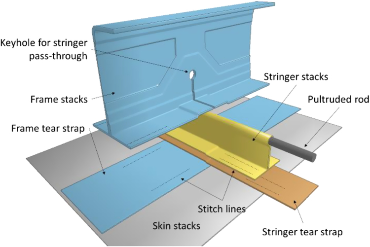
Figure 1. Exploded view of the PRSEUS concept.
The PRSEUS components discussed herein contain frames, stringers, and skins. PRSEUS is almost entirely composed of carbon fiber-reinforced polymers (CFRP) unidirectional plies. The baseline material architecture for PRSEUS is created with seven layers of CFRP at different fiber orientations, referred to as a stack, which produces an overall stiffness that is resistant to multiple loading directions. For the PRSEUS configurations used for the current study, each stack is arranged in a [+45/-45/0/90/0/-45/+45] sequence with a (44/44/12) fiber architecture, where the values are percentages of (0/±45/90) degree plies. The 0° fibers of the frame, skin, and frame tear strap align with the length of the frame, whereas the 0° fibers of the pultruded rod, stringer, and stringer tear strap align with the length of the stringer.
Each stack has a total thickness of 1.321mm (0.052in), with thicker sections created by layering stacks. The stacks are stitched together into a self-supporting preform using 1600 denier Vectran thread(13). Stitching allows the part to be assembled before curing, eliminating the need for many external connections and mitigating damage propagation. The final assembly is co-cured out of autoclave using Controlled Atmosphere Pressure Resin Infusion (CAPRI), which allows for large assemblies without sacrificing bond quality.
While the HWB concept promises improved fuel efficiency and better interior space utilisation compared to current aircraft configurations, new and unconventional design strategies for its primary structures and corresponding enabling manufacturing technologies are required to support the loading introduced by the unique geometry of HWB. By introducing a revolutionary damage-tolerant construction method, PRSEUS is capable of withstanding the complex loading expected in the HWB. However, while many proof-of-concept tests have been performed, accurate and high-fidelity computational tools are needed to develop PRSEUS further without excessive experimental cost. Such tools will also be necessary for commercial certification and implementation.
2.0 COMPUTATIONAL APPROACH
Composites are typically modeled using one of two scales. The first is a mesoscale approach in which each ply is individually modeled and the bonding between each layer is represented using cohesive zones. This modeling approach allows delamination to be directly calculated and observed, making it ideal for identifying damage at small scales as demonstrated in(Reference Gower, Cronin and Plumtree14–Reference Matzenmiller, Lubliner and Taylor16). However, for many structures larger than a simplified test article, the computational effort required to model each individual laminate is infeasible.
The second type of modeling approach utilises smeared (also called lumped) system properties. Although a smeared model does not explicitly account for the response of each individual ply and for delamination, it is much less computationally expensive, making it desirable for large-scale simulations. The smeared system approach has been utilised extensively by design-oriented works(Reference Behl, Joshi, Mehlig, Ali, Surti, Kim and Tamijani17) and has been shown to provide reasonably accurate global trends when no major failures occur(Reference Bergan18,Reference Przekop, Jegley, Rouse and Lovejoy19) . However, the removal of delamination mechanisms from the model causes the prediction of failure to deviate significantly from experimental observations(Reference Przekop, Jegley, Rouse and Lovejoy19,Reference Yovanof and Jegley20) .
The present work combines the strengths of the smeared and mesoscale approaches by utilising a hybrid-mesoscale approach. Instead of modeling each ply and interlaminar bond, the approach is scaled to model a stack and inter-stack bond as shown in Fig. 2. The result is a versatile modeling approach that can represent PRSEUS with a high-fidelity at a wide range of scales.
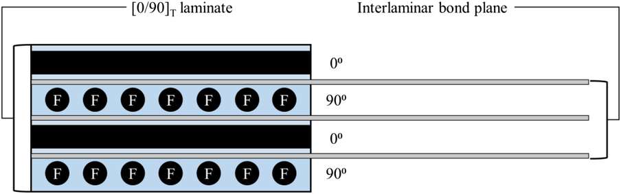
Figure 2. Illustration of the hybrid-mesoscale modeling approach.
Several well-established composite failure theories have been transferred into commercially available software. LS-Dyna offers few advanced composite damage models, those composite damage models however require more complicated input parameters that are not currently available in the public domain. On the other hand, the Chang-Chang failure criterion is one of the most commonly used due to its simplistic input requirements with reasonably accurate material responses when compared to the other predictive composite damage models, such as those available in LS-Dyna (i.e. Pinho et al(Reference Pinho, Darvizeh, Robinson, Schuecker and Camanho3)). Therefore, the analysis discussed in this work is performed using the Chang-Chang composite failure theory(Reference Chang and Chang21), as is implemented within LS-Dyna(Reference Hallquist22).
Damage is represented through property degradation, and when an element has reached complete failure, it is deleted. The inter-stack bonding is represented using a bi-linear cohesive zone. A mixed-mode condition allows both Mode I and Mode II separations to contribute to the final fracture based on a quadratic relation between crack energy and the experimentally determined energy release rate. The Dycoss Discrete Crack model is used to calculate the peak traction and uses the contact stiffness between adjacent stacks as the initial slope of the bi-linear traction-displacement law(Reference Lemmen, Meijer and Rasmussen23).
To effectively incorporate stitching, cable elements are applied to the model in addition to the tiebreak definitions that represent inter-stack epoxy bonding. Although performing experiments, such as a double cantilever beam test, can help with obtaining benchmark values for crack energy and energy release rate verifications for simple composite laminates, distinguishing the influence of stitching can be challenging. This is since in the presence of stitching epoxy bonds can still degrade under applied loading before stitches fail (when particularly subjected to shear loads). Additionally, each stitch creates a localised stress concentration, an effect that cannot be represented with a lumped tiebreak model. In this study, however, an overall knockdown factor was effectively derived and considered to account for the degradation of the mechanical properties including those of both stiffness and strength(Reference Horton24).
3.0 BUILDING BLOCK APPROACH
The methodology is developed using a building block approach. Analysis begins with the simplest case before moving to the more complex and larger scale. In each of these modules, the computational analysis is validated against a corresponding physical experiment.
3.1 Stringer model
Multiple PRSEUS stringer configurations have been proposed and tested, but the current work only discusses the Class 72 Type 1 stringer without extra adhesive examined by Leone et al.(Reference Leone11) A single stack is used for each of the components that comprise the stringer: the tear strap, pultruded rod, and overwrap. The pultruded rod has a unique, teardrop-shaped cross-section to minimise matrix-rich deposits near the web-rod intersection. The 0° fiber direction for each part is aligned with the longitudinal axis of the pultruded rod and perpendicular to the 0° fiber direction of the skin. The pultruded rod is made from Grafil 34-700WD carbon fibers with PUL6 epoxy resin. All of the stitching is performed using a spacing of 0.2 stitches per millimeter (5.08 stitches per inch). A schematic of the PRSEUS stringer considered herein is shown in Fig. 3.

Figure 3. Schematic of the PRSEUS stringer (all dimensions are in mm).
The computational representation of the stringer implements a combination of solid and beam elements to achieve an accurate response while maintaining a relatively low simulation time. The pultruded rod is represented by beams, which reduces the cross-sectional profile to a circle instead of a teardrop. Individual stitches are approximated by using cable elements (beams that only resist tension). Unlike a tiebreak model, this method allows stitches that span multiple stacks or follow an angled path. Solid elements are used for all of the stacks, with the previously discussed Dycoss Discrete Crack model governing inter-stack separation for both Mode I and Mode II. The development and setup are thoroughly discussed in(Reference Horton24,Reference Horton, Song, Jegley and Bayandor25) .
When compared to the experimental baseline and existing computational results, as shown in Fig. 4a, the current stringer model performs well. The model initially predicts the stiffness with 0.8% error and the peak load with less than 4% error. Additionally, a post-buckling response is captured, which is not observed in previous modeling attempts.

Figure 4. Loading versus displacement response for PRSEUS a) stringer b) tapered L-frame.
3.2 Frame stringer model
PRSEUS is enabling technology for the center section of an HWB aircraft because of the repeated pressure cycling of the non-circular shape. However, the concept could also be applied to traditional aircraft structures to reduce weight and improve efficiency. A typical cylindrical fuselage is not prone to the out-of-plane and bi-axial loads expected in an HWB configuration, so a tapered L-frame utilising significantly less material was designed. The tapered L-frame has a complex construction with a non-uniform cross-section and requires significantly more stitching than the previously studied HWB frame. A schematic of the cylindrical fuselage frame proposed is shown in Fig. 5 with section views.
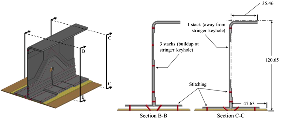
Figure 5. Schematic of the tapered L-frame with cross-section cutouts (all dimensions are in mm).
The layering that takes place at the intersection between the stringer and frame adds to the complexity of the structure. In a traditional frame-stringer intersection, a large region is cut out of the frame web for the entire stringer to pass through. In PRSEUS, only a keyhole that matches the size and shape of the stringer web and pultruded rod is removed. Additionally, the flange portions of the frame are layered over the tear strap and flange of the stringer. The skin, flanges, and tear straps are stitched together while the keyhole surface is in contact with the stringer and connected with the epoxy.
The computational modeling of the frame is based on the validated stringer model, with the same elements and assumptions applied throughout. The layering of the stacks introduced by the intersection between the frame and stringer must be accurately modeled, with stack terminations to allow correct load transfer. Otherwise, the results greatly under-predict the strength of the structure and indicate a highly non-linear stiffness(Reference Horton, Song, Jegley and Bayandor26).
The response of the current model, two experimental specimens, and a previous model(Reference Leone11) are shown in Fig. 4b. Only two specimens were tested so the range of scatter in response is limited; however, the numerical prediction agreed well with one of the experimental trials, indicating that the methodology is capturing many of the same primary damage mechanics. The error in the predicted stiffness is no more than 4.6% during the initial loading and just before buckling and less than 1% error during the majority of the softening regime. The difference in the displacement at which buckling occurs is only 0.028mm (0.0011in), while the error in the predicted buckling load is just 3.6%. The developed methodology has the capability to accurately predict the buckling load but does not necessarily capture the ultimate failure behavior observed in the experimental testing. The local element deletion at the estimated point of ultimate failure is shown in Fig. 6 with labels in order of failure occurrence. During loading, a small amount of element erosion occurred underneath the frame base and along the stringer tear strap on the side closer to the symmetric boundary. As the structure continues to compress, the stack terminations at the buildup around the stringer keyhole erode. After the frame entered the post-buckling regime, the final two cracks appear almost simultaneously. The first is the crack at the top of the web, extending toward the top flange and the second appears almost directly below at the stack dropdown. Due to the buildup around the stringer keyhole, no failure occurred in that region. These characteristics are representative of the experimental test, which observed that the crack could propagate on either side of the stringer.

Figure 6. Sequentially labeled locations of local element failure for the tapered L-frame.
4.0 LARGE SCALE REPRESENTATION
As part of the certification process, any new airframe design must be evaluated for crashworthiness(27). A commonly performed test is the fuselage section drop, which tests the response of a structure under dynamic conditions. Since no physical test section of a PRSEUS circular fuselage has been constructed, the goal of the numerical investigation is to provide insight into how a full-sized cylindrical section of PRSEUS would respond in such a scenario. The use of a reduced fuselage section for modeling a structure at an appropriate scale for a commercial passenger aircraft was necessary to keep the simulation time feasible. The total diameter in the model is 3.76m (12.34ft), which is approximately the same diameter as a Boeing 737. The model of the lower half of a fuselage section was created with the successfully validated stringer and frame-stringer intersection models previously described.
No specific PRSEUS barrel fuselage design has been proposed, so the stringer spacing of 0.15m (6in) used for the HWB configuration is implemented. In total, the PRSEUS reduced fuselage section comprises 37 substructures, as illustrated in Fig. 7. The tapered L-frame substructure for the PRSEUS fuselage uses the same construction as the model previously described. Additionally, the simulation is conducted with both stitched and unstitched configurations of PRSEUS. A prior work computationally demonstrated the differences in damage progression that stitching can have for quasi-static loading conditions(Reference Horton, Song, Jegley and Bayandor28), but the work described herein is the first to investigate a dynamic loading case.
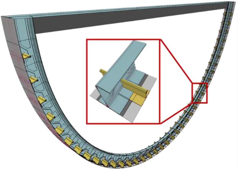
Figure 7. Illustration of the entire reduced section model with close-up of a single substructure.
In the absence of any detailed information, a simple connection was created to attach the passenger floor to the frame. The passenger floor is defined as a shell that is directly attached to the passenger floor without simulating the effect of rivets or bolts. Additionally, a vertical stiffener was created underneath the floor to provide support. The support was created by removing the top flange and extending a 0.126m (5in) section of the frame web along the bottom of the passenger floor. The passenger floor is assumed to be a simplified, linear elastic-plastic form of Al 2024-T3 to reduce the computational expense. In this analysis, the passenger floor is not the focus of the investigation but is required for a continuous transfer of load.
The section drop is conducted for an impact velocity of 9.1m/s (29.9ft/s) onto a rigid surface, with gravity applied over the domain. Symmetric conditions are applied to both the front and rear face of the fuselage section to simulate the response of an interior frame member instead of a free edge. Even though a line of symmetry exists along the vertical centerline of the model, a half-symmetric assumption was not made because preliminary tests showed the symmetric condition to cause local element failure at the boundary.
The fuselage section is shown in Fig. 8 near the beginning and end of its deceleration, with contours of vertical velocity. These contours remain reasonably consistent between stitched and unstitched configurations, so only the stitched response is shown for reference. As the fuselage decelerates, three primary regions of damage develop. The first, which initiates almost instantly, is at the bottom center of the frame (1), resulting in a crack extending from the top of the center stringer through the frame flange. The second place that damage develops is 30-50° from the bottom center of the frame (2). No major failure is observed, but delamination is initiated and extends through this region. Finally, near the end of the deceleration, the frame web connected to the passenger floor and stiffener below (3) begins to delaminate from the surrounding frame.

Figure 8. Contours of vertical velocity with sequentially marked locations of damage formation.
While the global response of the stitched and unstitched PRSEUS fuselage sections are similar, the development of local damage in each of the indicated regions is quite different. At the first location (1), the rate of damage progression is slower in the stitched fuselage. This is since the stitches can effectively arrest cracks and prevent them from propagating through the rest of the structure. Midway along the frame at (2), the opposite phenomenon is observed.
In this case, the stitches over-constrain the deformation of the stacks and cause greater stress concentrations. This behavior has been reported for ballistic impact investigations with other stitched composites and warrants further study(Reference Caprino, Lopresto and Santoro29). At the connection to the passenger floor (3), the unstitched model predicts the formation of a long crack that extends through the frame. No such crack is observed in the stitched model due to the reinforcement provided by the stitches.
5.0 CONCLUSION
PRSEUS is among the leading concepts that could produce lighter, fuel efficient, and damage tolerant structures. Although the concept was proposed as an enabling technology for HWB, PRSEUS would benefit traditional configuration aircraft as well. Based on the proof-of-concept tests that have been performed for PRSEUS, an effective computational methodology is described in this work. Such computational tools are necessary for the development and certification of PRSEUS for future commercial aircraft.
Prior to this study, all experimental and analytical evaluations for PRSEUS were conducted under quasi-static conditions. The work presented herein for the fuselage section is the first time that dynamic effects have been studied for PRSEUS. While the reinforcement provided by stitching arrested delamination, this reinforcement may over-constrain the structure in some situations. Further studies will more thoroughly investigate the dynamic response of PRSEUS and possibly suggest new configurations. In addition to local damage progression, the methodology may be used to estimate important factors such as G-loading at the passenger floor, which is a critical element in certification analysis and assessment of any aircraft. Overall, improving the level of understanding of the response of PRSEUS structures, gained through the application of the presented methodology, can facilitate and guide future iterations of the concept that can effectively contribute to the development of a viable structural design strategy for future fuel efficient HWB aircraft.
ACKNOWLEDGEMENT
The research grant awarded by and support received from the NASA Environmentally Responsible Aviation (ERA) Program and constructive feedback concerning PRSEUS from Mr. Alex Velicki from The Boeing Company are acknowledged and highly appreciated.


