NOMENCLATURE
- AL
Approach and landing
- BPR
Bypass ratio
- CL
Climb
- CR
Cruise
- DE
Descent
- EIS
Entry into service
- FMU
Functional mock-up unit
- GTF
Geared turbofan
- HPC
High-pressure compressor
- HPT
High-pressure turbine
- ICAO
International civil aviation organization
- IPC
Intermediate-pressure compressor
- IPT
Intermediate-pressure turbine
- ISA
International standard atmosphere
- LPT
Low-pressure turbine
- NGV
Nozzle guide vane
- OPR
Overall pressure ratio
- PRn
Pressure ratio split exponent
- SFC
Specific fuel consumption
- SFN
Specific thrust
- TO
Take-off
- TOC
Top of climb
- VcoldQhot
Jet velocity ratio
1.0 INTRODUCTION
The aviation sector is in a continuous quest for advanced engine design, which makes the best out of the temperature-limited Brayton cycle, and for unconventional aircraft and propulsion architecture to achieve the emission reduction standards(1–Reference Kallas and Geoghegan-Quiin3). Propulsion systems powered from electrical systems hold the potential to achieve zero fuel consumption. To this end, multiple electrical-powered prolusion-based aircraft configurations have been explored by NASA and Bauhaus Luftfart for the assessment of their potential benefits(Reference Bradley and Droney4–Reference Stückl, Van Toor and Lobentanzer11). There is an agreement that the technology level, as it stands today in electrical energy storage systems, is not adequate for the feasibility of fully electric large subsonic aircraft for entry into service (EIS) prior to the year 2045(Reference Jansen12). Having said that, hybridisation is considered a feasible and compromised solution for a greener near future and has become the cornerstone for major research work. The research exploration was largely based on the conceptual level, studying for the feasibility of the hybrid aircraft, with an end objective of benchmarking desirable technology for the electrical system components(Reference Isikveren13–Reference Lents20).
However, it is observed that there is less focus in the work for the detailed hybridised gas turbine off-design performance. Freeh et al(Reference Freeh, Steffen and Larosiliere21) investigated hybrid off-design performance in 2005, but, for the case with a solid-oxide fuel cell as auxiliary power unit. Given the fact that aero engine operation is a multi-constrained function of different operational conditions, hybrid operation adds further complexity having two sources to manage for their optimum utilisation. It would be worth the effort to analyse the behavioural interaction of the two energy systems when scheduled for a varying degree of hybridisation. Furthermore, such study could be valuable input for the research community and could lead the direction of future research for the conventional aero engine industry. As hybrid propulsion for large aircraft may be expected within the timeframe of the near future, around 20 years from now, a turbofan with the same(Reference Isikveren10) estimated year technology should be established as the baseline for a fair comparison.
In this paper, a study of the off-design performance of an aircraft conventional gas turbine under various degree of hybridisation is presented. A two-and-half-shaft geared turbofan (GTF) for basic A320-200 type aircraft was established as the baseline engine with EIS year 2035 technology level assumptions. Parallel hybridisation was adopted as one of the most convenient means of electrifying the existing aircraft gas turbines. This was achieved assuming a coupling of an accessory gearbox to the low-pressure shaft at one end and an electrical motor on the other end, in a similar way as the mechanical design for power off-take in a conventional engine. An existing engine equipped with such provisions for power off-take is the Rolls-Royce Trent 1000. As required by the more electric aircraft Boeing 787, which features no bleed air but a high power extraction requirement, extracting power from the intermediate-pressure shaft has the benefit of enabling high power off-take and improving operability of the intermediate-pressure compressor (IPC) at low power. More information can be found in Ref. (Reference Lupelli and Geis22).
2.0 METHODOLOGY
2.1 Modelling tools
For engine/aircraft performance prediction, an in-house tool described in Refs. (Reference Kyprianidis23–Reference Kyprianidis25) was used along with the open-source high-performance computing platform for systems analysis and multi-disciplinary optimisation OpenMDAO(Reference Hwang26,Reference Gray27) . OpenMDAO allows integration of different models created with different tools. In this case, the engine/aircraft performance modelling tool introduced earlier was based on Fortran code, with a rubberized-wing aircraft model built-in. For every engine design variant, the rubberized-wing aircraft was scaled on a constant wing loading basis to achieve a design range mission. Consecutively, the scaled aircraft was used in conjunction with a typical business case mission for predicting block fuel. The aircraft dimensions modelling was based on Ref. (Reference Jenkinson28), while aircraft weight modelling followed the principles outlined in Refs. (Reference Jenkinson28–Reference Torenbeek30). The aircraft aerodynamics was modelled according to Refs. (Reference Jenkinson28) and (31), and aircraft performance modelling was based on Refs.(Reference Jenkinson28) and (Reference Laskaridis32). As was developed under European Union Framework 6 and 7 collaborative projects (VITAL, NEWAC, DREAM), the tool has been extensively used in future aero engine conceptual design within the projects. Representative work can be found in Refs. (Reference Kyprianidis25,Reference Kyprianidis and Rolt33–Reference Kyprianidis and Dahlquist37).
The modelling of sizing and weight estimation of the engine was based on Modelica, and the model was compiled to Functional Mock-up unit (FMU)(38). The FMU was then accessed via a wrapper class, which is based on the Python package PyFMI(Reference Andersson, Åkesson and Führer39,40) , within OpenMDAO. A simplified process of estimating engine component dimensions and weight was used here. After the engine performance model has been set up, empirical correlations based on the aerodynamic design point data were used to size the engine core component by component, from fan to the low-pressure turbine (LPT)(Reference Saravanamuttoo41,Reference Grieb42) . With the sizing results, weight estimation of the engine was largely built on the calibration of public domain information available for the existing GTF Pratt & Whitney 1100 G(43) and methods described in Ref. (Reference Lolis44).
2.2 Baseline GTF establishment
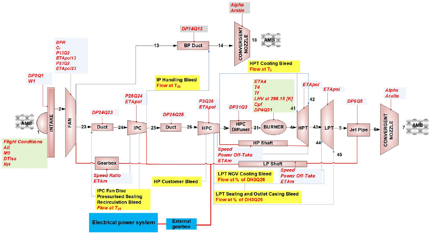
Estimation of the year 2035 turbomachinery polytropic efficiencies was based on the correlations provided in Ref. (Reference Samuelsson, Kyprianidis and Grönstedt45). The schematic plot of the baseline GTF with access to the indicated electrical power system is illustrated in Fig. 1. Key parameters assumptions are shown in Table 1.

Figure 1. Schematic plot of the baseline GTF with access to the electrical power system indicated.
Table 1 Key parameters assumptions for the baseline GTF establishment
The optimisation process of the baseline GTF included the design space exploration of four key performance parameters: specific thrust (SFN), ideal jet velocity ratio (VcoldQhot), overall pressure ratio (OPR) and pressure ratio split exponent (PRn) at cruise. Definitions of the four performance parameters are given below:
1. SFN – engine net thrust divided by fan inlet mass flow.
2. VcoldQhot – Bypass nozzle ideal jet velocity divided by core nozzle ideal jet velocity; ideal jet velocities are calculated assuming full expansion of the jets as in an ideal convergent-divergent nozzle.
3. OPR – Compressor exit pressure divided by the fan inlet pressure.
4. PRn –
 ${\log _{OPR}}{{IPC\,exit\,pressure} \over {Fan\,inlet\,pressure}}$

Single parameter studies of the four parameters at cruise operating point were performed to select the optimal baseline GTF. Only one parameter of the four was varied at one time, focusing on the isolated effect of each parameter on SFC and mission fuel burn. The design space explored in this study is given in Table 2. The final baseline was selected as the case with the minimum fuel burn for the pre-defined business case mission. Turbine inlet temperature T4 was fixed at hot-day top of climb (TOC) (ISA+10). Cooling mass flow fractions for the two turbines were calculated to match the fixed-metal temperatures, as indicated in Table 1, at hot-day take-off condition (ISA+15). The maximum nacelle diameter of the turbofan is defined as 2.65 m based on the information retrieved from the latest A320 aircraft characteristics(46). The substantial effect of short compressor last blade height is considered in this study with the compressor polytropic efficiency correlation provided by Ref. (Reference Kyprianidis and Rolt33).
Table 2 Design space explored of the four key performance parameters

2.3 Hybridisation of the baseline
The study of the parallel hybridisation of the baseline engine comprised two parts. The first part was analysing the off-design performance of the engine with various degrees of hybridisation at different mission phases. The electrical power input to the low-speed shaft was varied from –2,000 kW to 2,000 kW. Negative value means a power flow from the gas turbine to the electrical power storage system, just like conventional power off-take, while positive value means electrical power input to the low-speed shaft. The maximum value corresponded to approximately 12% of the take-off LPT power and 43% of the cruise LPT power of the baseline GTF. The hybridisation was kept constant for each main mission phase, taxi (including both in and out), take-off (TO), climb (CL), cruise (CR), descent (DE), as well as approach and landing (AL). Since the paper is focusing on the off-design performance of the hybridised gas turbine, electrical power system related modelling was not included. No loss for the power transmission was assumed in this work, while the weight penalty incurred was also excluded. Nevertheless, these practical considerations are discussed in the end of the ‘Results’ section, where their impact on aircraft performance is illustrated through simple calculations and exchange rates.
The second part of the hybridisation study was focused on establishing a strategy for the improvement of the performance of the baseline GTF utilising hybridisation. After analysing the results from the first hybridisation study, two strategies were evaluated. One was minimising the use of compressor handling bleed by charging the battery during part-load operation mission phases, and another one was gas turbine re-design through the hybridisation of the take-off operation.
2.4 Mission specifications
A design range mission of 4,800 km and a business case mission of 925 km were pre-defined with a fixed-thrust requirement for all the mission phases. Details of key operation points are defined in Table 3. The descent point shown together with take-off, TOC and cruise is from one of the simulated descent segments. The GTF off-design performance detailed results showing later will be based on these four points as well as the approach and landing and taxi operations. For the approach and taxi phases, the engine thrust was set to be 30% and 7% of the take-off thrust, respectively, as introduced by ICAO engine emissions certification procedure.
Table 3 Key mission points data

3.0 RESULTS
3.1 Baseline GTF optimisation results
As mentioned in the methodology section, the baseline GTF was optimised based on the single parameter studies of the four key parameters: OPR, VcoldQhot, SFN and PRn. It is well known that, an increasing OPR can principally improve the gas turbine performance by increasing the thermal efficiency of the cycle. Two of the most important drawbacks of increasing the OPR in practice are the reduced compressor last blade height and the higher turbine cooling demand. In this study, these two effects were captured using high-pressure compressor (HPC) efficiency correction and matching the cooling flow need for a fixed-turbine metal temperature. The results shown in A1 and A2 of Fig. 2 suggest an optimal value of 55 for the cruise OPR, read from the data with HPC efficiency correction.
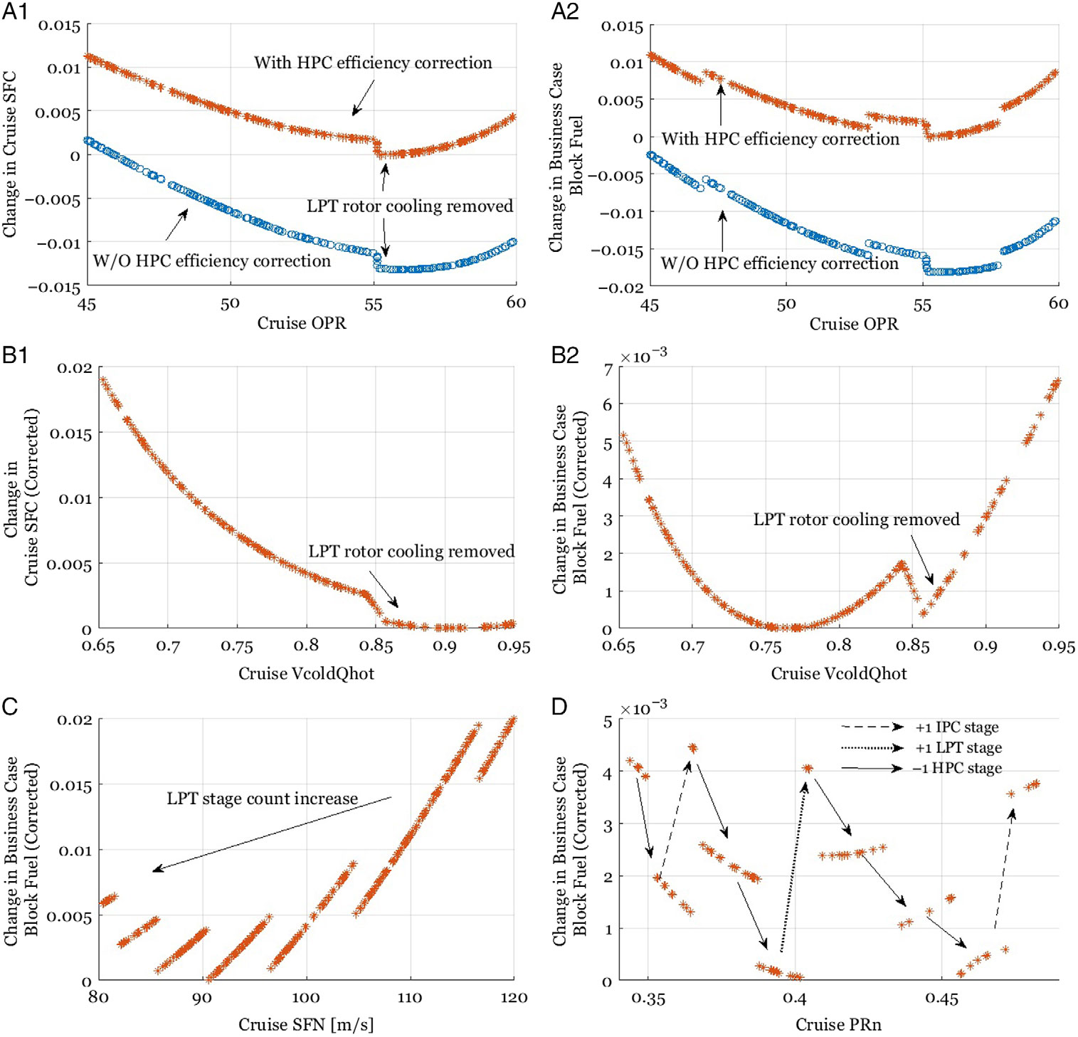
Figure 2. Baseline design space exploration. A1, A2 – Cruise OPR single parameter study result; B1, B2 – Cruise VcoldQhot single parameter study result; C – Cruise SFN single parameter study result; D – Cruise PRn single parameter study result.
An interesting observation here is that the cruise OPR around 55 is actually a transition region to the removal of the LPT rotor cooling demand. With the fixed-turbine inlet temperature at TOC and the fixed-pressure ratio split exponent at cruise, the increased OPR results in higher compression work done by the HPC; hence, a higher drop in temperature through the high-pressure turbine (HPT) and a lower LPT inlet temperature. Whilst the required total cooling flow for both turbines to maintain a constant metal temperature increases as the OPR increases – since the cooling flow temperature increases – reducing the need for LPT cooling flow. From cruise OPR 55 and above, no LPT rotor cooling flow is needed to satisfy the turbine metal temperature constraint set in Table 1; hence, the LPT rotor cooling flow is set to zero in the performance model. In total, the optimal OPR value is mainly determined by two trade-offs. As OPR increases, the HPT cooling flow required increases as does the HPT efficiency. On the other hand, the decreasing LPT cooling reduces cooling flow losses, as well as the LPT efficiency, until the LPT rotor cooling flow is set to zero. Beyond that, the further dropped LPT inlet temperature lowers the LPT efficiency more than the gain from the reduction of LPT nozzle guide vane (NGV) cooling losses. In addition, at higher OPR, the HPT cooling flow losses increase faster than the benefit of running the cycle at higher temperatures.
Optimal jet velocity ratio in the range of 0.8 to 0.85, as an important indicator for the transfer efficiency, is widely suggested by the authors in Refs. (Reference Kyprianidis, Rolt and Grönstedt34,Reference Walsh and Fletcher47 and Reference Guha48) for modern turbofans. Results shown in B1 of Fig. 2, however, suggest an optimal cruise VcoldQhot of nearly 0.9 for the minimum cruise SFC. This is mainly due to the high efficiencies assumed for the fan and the LPT for EIS 2035. Nonetheless, within the range from 0.85 to 0.95, variations of the cruise SFC are neglectable. For the minimum block fuel shown in B2 of Fig. 2, which is largely affected by the mission specifications and engine sizing and weight estimation techniques, an optimal cruise VcoldQhot of 0.77 is obtained. With LPT rotor cooling demand removal at higher VcoldQhot, an equally good choice can be found around 0.86.
Decreasing SFN will increase turbofan propulsive efficiency, while the resulting increased nacelle diameter and drag will offset part of the benefit. Civil turbofans tend to have a lower SFN level than what is fuel optimal, as it gives a lower jet velocity and hence a lower jet noise. On the other hand, more attention needs to be paid on the possible higher fan noise level with decreased SFN. Another important consideration for SFN is shown in sub-figure C of Fig. 2, that is, the LPT stage count increase due to increased bypass ratio (BPR) and decreased fan pressure ratio. The same observation is reported in the multi-disciplinary analysis of a geared intercooled core turbofan presented in Ref. (Reference Kyprianidis, Rolt and Grönstedt34). These effects indeed set the optimal cruise SFN to around 90 m/s before the nacelle diameter penalty issues kick in. The single parameter study results of varying cruise PRn, see D of Fig. 2, is basically determined by the engine-sizing techniques. A general observation here is that an increasing PRn may lead to an increase of IPC and LPT stage count accompanying the reduction of HPC stage count. Though the optimal PRn here is found as 0.4, one can design the LPT with higher stage loading and then delay the LPT stage count increase for a possible block fuel decrease with higher PRn. It is also another choice of removing 3 HPC stage counts but having one more LPT stage count with PRn 0.46 for an equally good block fuel result. After screening the four single parameter studies, the baseline GTF is selected and key parameters are defined in Table 4.
Table 4 Established baseline GTF key parameters

3.2 Hybridisation results
Results of hybridising the established baseline GTF are shown in the following sections. The block fuel shown includes only the fuel burned inside the combustor of the gas turbine. The consumed electrical energy is not converted into equivalent fuel burn and not included in the block fuel shown below.
3.2.1 Hybridisation study results: part 1
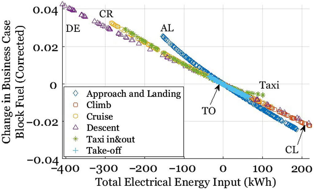
Results of the block fuel change by introducing hybridisation are shown in Figs. 3 and 4. As expected, the introduction of the electrical power to the low-speed shaft results in a block fuel reduction, and the reduced fuel is basically replaced by the consumption of the electrical energy. The relation is nearly linear for all the cases except the approach and landing, and taxi phases. For the taxi operation, this is because the HPC handling bleed is set as constant and the IPC handling bleed is varied to excessively high value for a sufficient surge margin. When the electrical power input increases, the IPC handling bleed increases and cancels out the benefit from the electrical power input. For the approach and landing phase, a higher power flow from the turbofan to the electrical power system is, however, detrimental to the engine efficiency. On the other hand, more electrical power input benefits the approach and landing phase more than the other operating conditions.
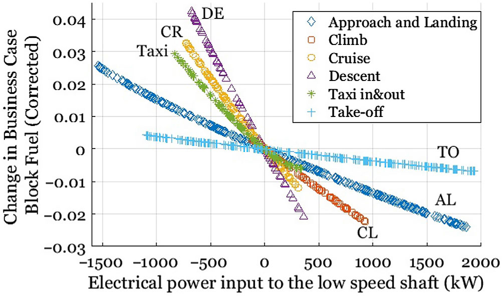
Figure 3. Hybridisation study part 1: Electrical power input versus block fuel (UP).

Figure 4. Hybridisation study part 1: Total electrical energy input versus block fuel.
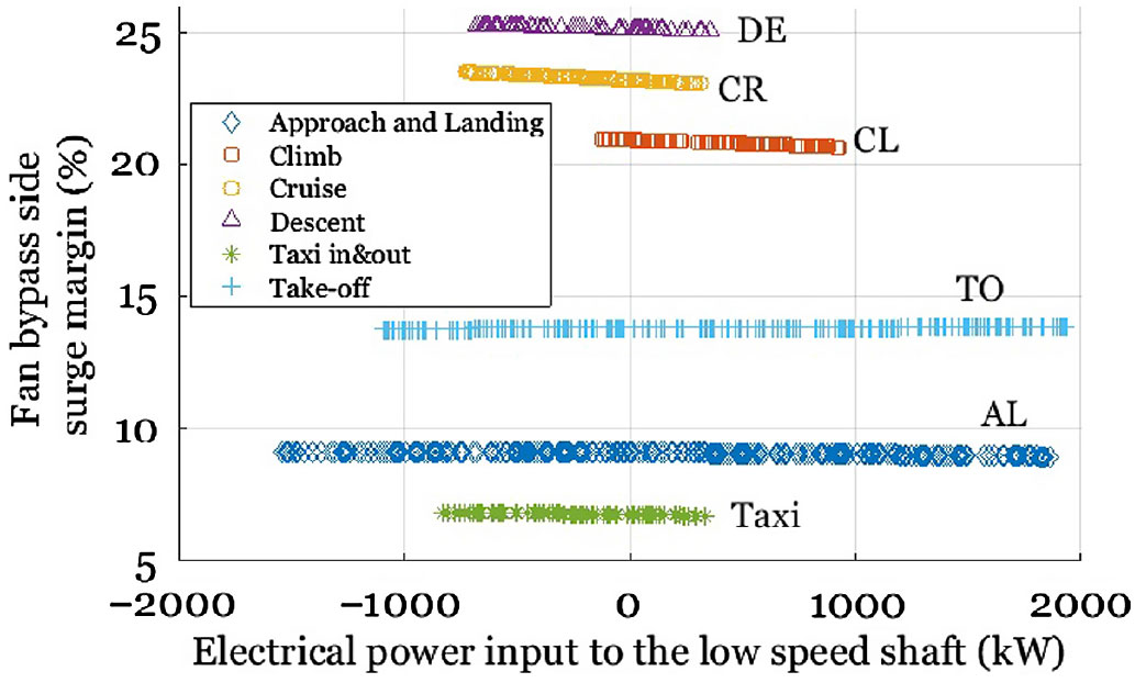
Variations of the surge margin of the fan and the compressors due to various degrees of hybridisation are shown in Figs. 5–8. The typical surge margin that is considered for transient manoeuvres is about 10%–15%(Reference Walsh and Fletcher47). The surge margin used in this paper is defined as the distance from the operating point to the surge line at constant corrected mass flow. For critical low-load operations such as approach and landing, taxi and descent, compressors handling bleeds are used to keep the surge margins above 10% for the nominal case without hybridisation. The same bleed settings are kept for the other hybridisation cases to show the effect of the hybridisation.

Figure 5. Hybridisation study part 1: Fan bypass side surge margin versus electrical power input.
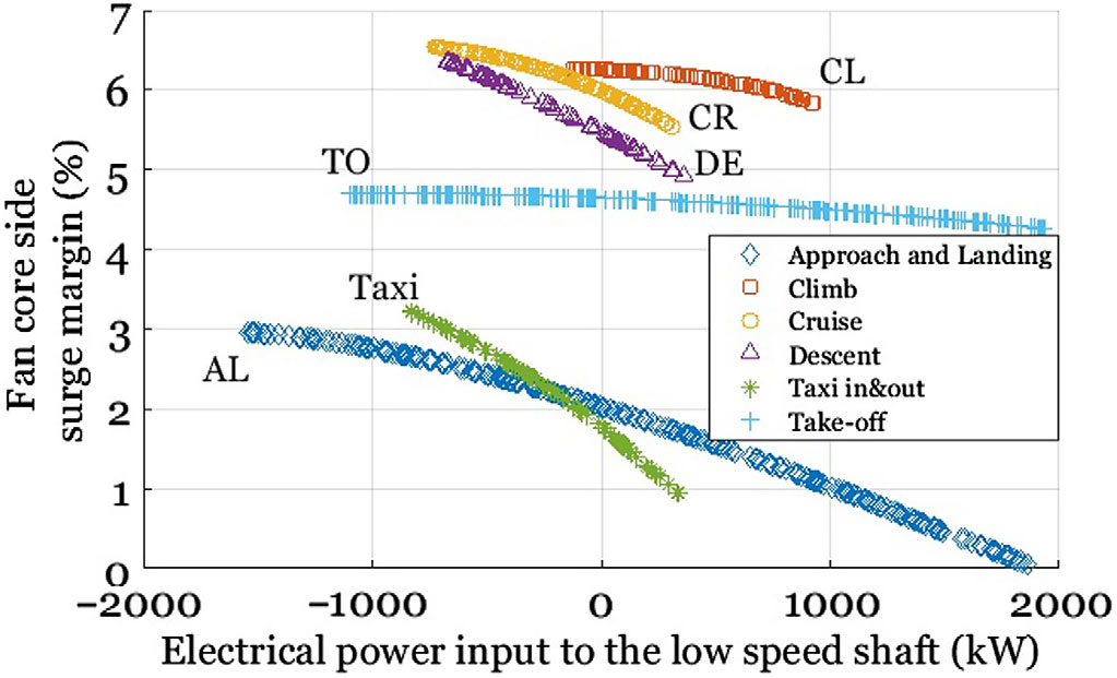
Figure 6. Hybridisation study part 1: Fan core side surge margin versus electrical power input.
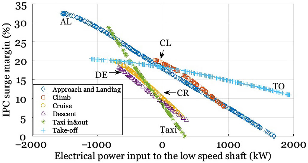
Figure 7. Hybridisation study part 1: IPC surge margin versus electrical power input.
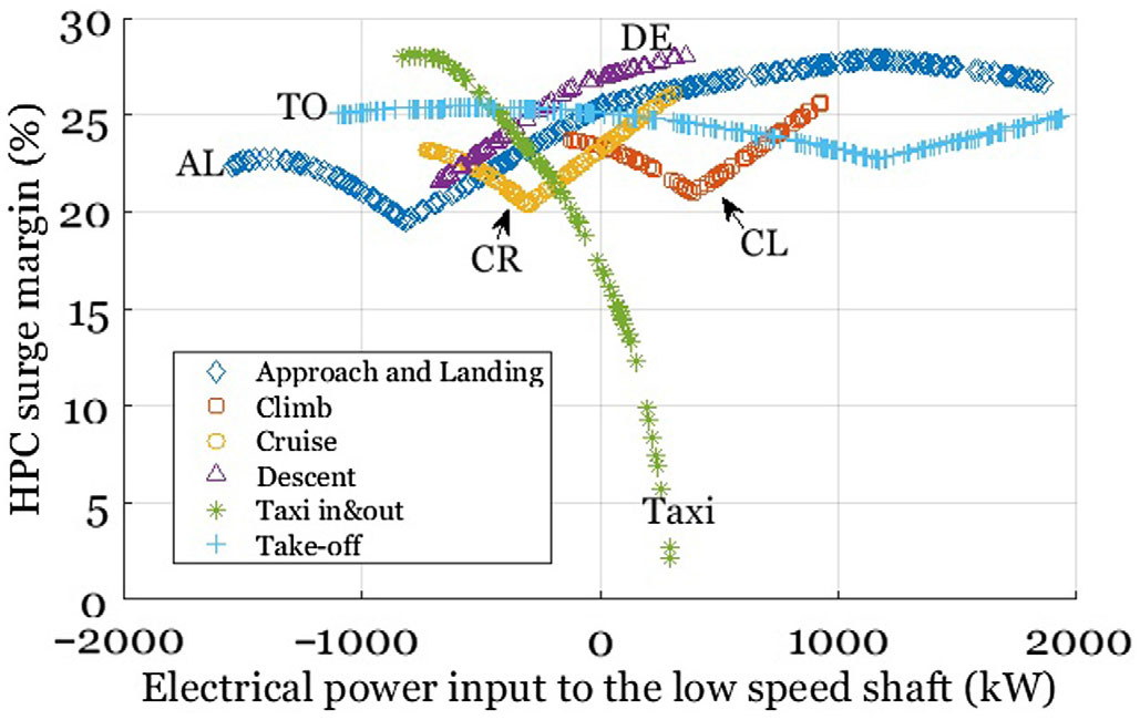
Figure 8. Hybridisation study part 1: HPC surge margin versus electrical power input.
Among the surge margin plots of the fan and the compressors, it is expected that the fan bypass side surge margin stays nearly constant with different electrical power input level. The working line of the fan bypass is dictated primary by the bypass nozzle capacity and by ram pressure ratio once the nozzle unchokes at lower forward flight Mach numbers. Fan core on the other side is affected but relatively less than the IPC. With more electrical power input, the operation of the IPC is moving towards the surge line mainly because of the decrease of the required core mass flow. As the low-speed shaft is rotating faster with more electrical power input, the fan speed is increased as well as the thrust. Considering the fixed-thrust requirement, the fuel flow and the turbine inlet temperature must be reduced. Hence, the high-speed shaft will reduce its speed and the mass flow through the core will decrease. Targeting the resulted reduction in surge margin of the IPC when electrical power is added to the low-speed shaft, Trawick et al. has reported their work applying variability on the low-pressure system in Ref. (Reference Trawick49). At the taxi phases, the HPC surge margin suffers mainly from the spooling down of the high-speed shaft. However, taking power from the low-speed shaft improves the surge margin of the IPC as well as the HPC operation during taxi.
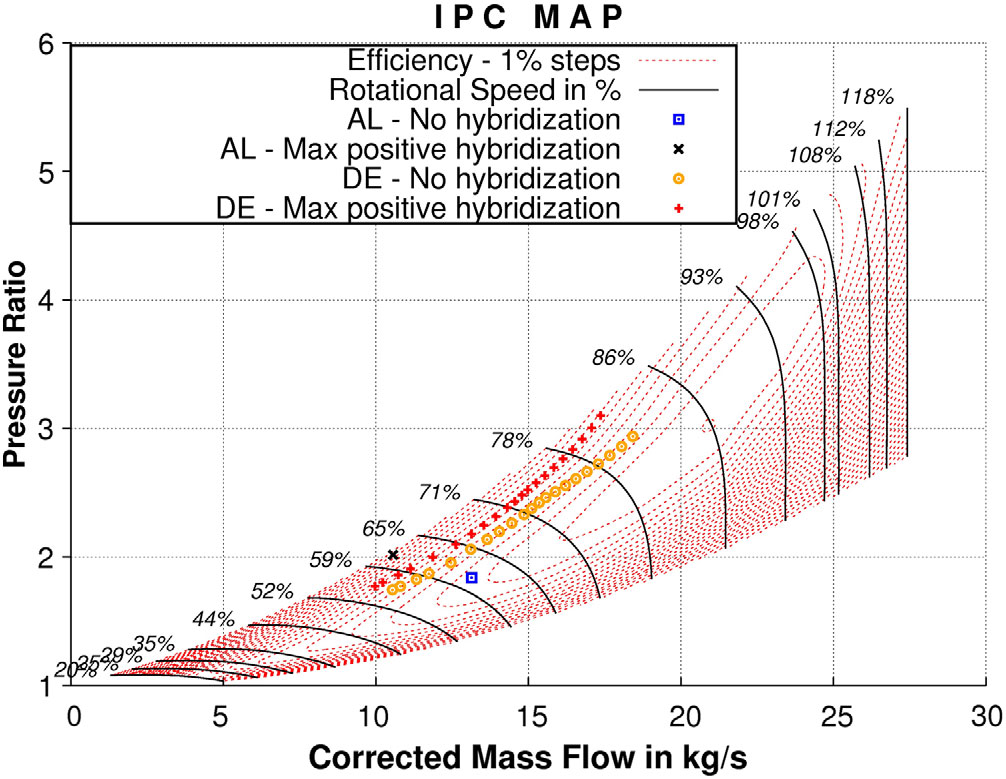
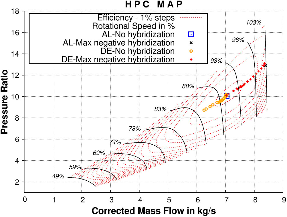
From Figs. 3–8, one can see that the highest positive electrical power input is less than the pre-defined maximum value, and the highest power output from the shaft is limited. The major reason is IPC and HPC operability. For the increase of positive electrical power input, the fast move of the IPC operation towards surge limits the space for external power boost. Meanwhile, the high electrical power output from the shaft has the added challenge of going beyond the maximum HPC rotational speed. Taking the hybridisation of descent as well as approach and landing as an example, the IPC and HPC maps are shown in Figs. 9 and 10. It is quite clear that, from the IPC map, the IPC operation hits the border with maximum positive hybridisation at approach and landing operation. In the HPC map plot, the HPC operation with maximum negative hybridisation at descent hits the rotational speed limit of the map.

Figure 9. Hybridisation study part 1: IPC operating points for positive hybridisation at descent and at approach and landing.

Figure 10. Hybridisation study part 1: HPC operating points for negative hybridisation at descent and at approach and landing.
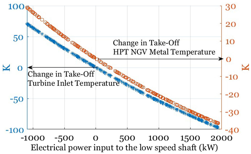
More importantly, critical design considerations for conventional aircraft gas turbine are the metal temperatures at hot-day take-off and the specific fuel consumption at cruise. Through the hybridisation of the take-off phase, see the positive electrical power input in Fig. 11, a considerable reduction in the turbine inlet temperature is observed. Hence, a reduced HPT metal temperature is expected. For this case, 500 kW electrical power input could help to lower the metal temperature at hot-day take-off to about 10 K. As the maintenance cost of the modern turbofans is strongly affected by the durability of hot section components, particularly at the peak temperature operations, the life of the hot section can be improved through boosting the take-off operation.

Figure 11. Hybridisation study part 1: Change in turbine inlet temperature and HPT NGV metal temperature versus electrical power input, take-off phase hybridisation.
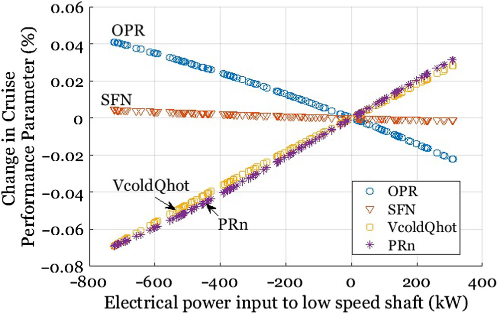
Besides the negative effect on IPC surge margin, boosting the baseline gas turbine during cruise moves the operation further away from the design point, hence downgrading the engine performance. As can be seen in Fig. 12, about 300 kW electrical power boost decreases the cruise OPR by 2% and increases the cruise jet velocity ratio by 3%, whereas the SFN stays nearly constant. As the mechanical design is fixed here, the effect of PRn variation can be ignored. These trends are expected and, as explained earlier, the lower core mass flow and reduced HPC rotation speed are the main reasons.

Figure 12. Hybridisation study part 1: Change in key performance parameters versus electrical power input, cruise phase hybridisation.
3.2.2 Hybridisation study results: part 2
3.2.2.1 Compressor handling bleeds minimisation
At part-load operations, compressors handling bleeds are normally used to avoid surge. The introduction of the electrical power to the low-speed shaft at these operations makes the condition even worse. On the other hand, compressor handling bleed is essentially a waste of energy. For the hybridisation of the existing turbofans, one can choose to charge the battery to move the compressor operation away from surge at low-load operations, such as descent, approach and landing, and taxi phases. Given that, Fig. 13 shows the surge margin of the IPC and HPC for the hybridisation cases without any compressor handling bleeds at the above-mentioned part-load operations. Following the same principle, Culley et al in their latest paper(Reference Culley, Kratz and Thomas50) proposed a way of using the electric machines as engine actuators during the transient to improve the turbine operability.
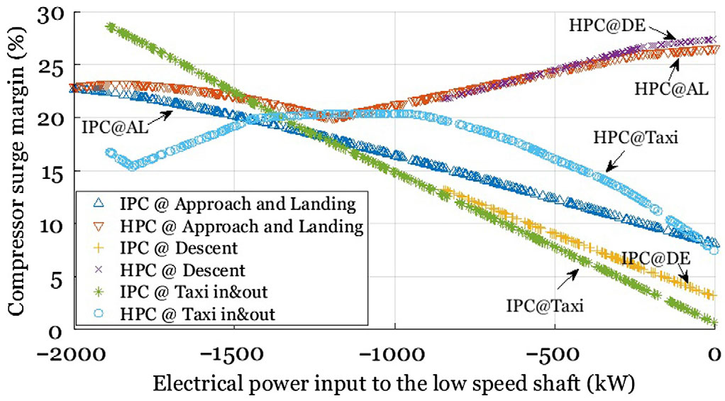
Figure 13. Hybridisation study part 2: Surge margin of compressors with negative hybridisation at low-load operations, no handling bleeds used.
To be able to eliminate the compressors handling bleeds while keeping the surge margin to a minimum requirement of 10%, the power bleed from the low-speed shaft must be larger than 580 kW, 240 kW and 650 kW, respectively, for the descent, approach and landing, and taxi operations. For the specific mission defined in this paper, the total energy output is about 570 kWh in total. The generated electrical energy can be used to boost the take-off and climb phase and cover the customer power off-take.
Beyond the study performed and results presented, it is interesting to consider the start-up of the hybrid engine until it reaches the self-idling speed. After the high-speed shaft spun up using conventional engine start means, ignition turned on and light fuel injected, a positive hybridisation can be introduced. This can help the low-speed shaft to overcome the large inertial resistance and hence reach its speed threshold more quickly; as assumed in this paper, that the electrical booster is mechanically connected to the low-speed shaft. However, this may adversely increase the demand of compressor bleeds during start-up. On the other hand, if the mechanism of switching the mechanical connection to the high-speed shaft during start-up exists, the auxiliary power unit may be replaced, along with the air turbine starter and associated components.
3.2.2.2 Gas turbine redesign through hybridisation of take-off
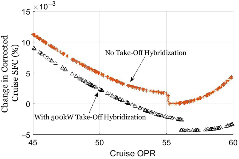
With a fixed-turbine metal temperature requirement, the turbofan turbine cooling system can be re-calculated for take-off hybridisation. In terms of the thermal design point of the gas turbine, the hot-day take-off (ISA+15) was simulated to define the cooling flow needed for the turbine. Figures 14 and 15 present the results of repeating the single parameter study in the baseline establishment section. However, only the variation of OPR is repeated here for demonstration, as the major effect is similar to all the cases.

Figure 14. Hybridisation study part 2: Change in cruise SFC through gas turbine redesign with take-off hybridisation.

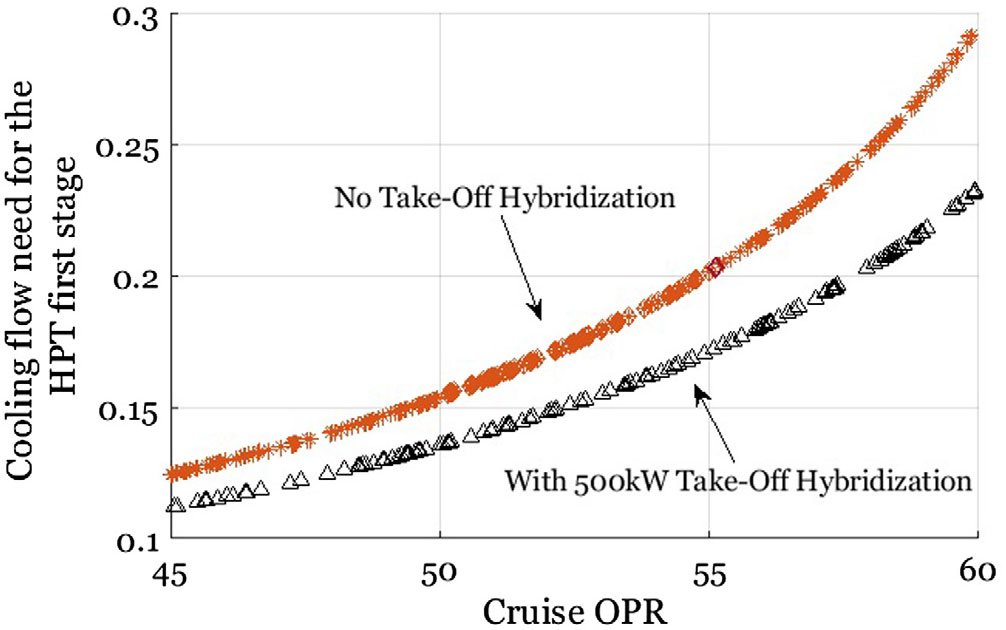
Figure 15. Hybridisation study part 2: Change in HPT first stage cooling flow need through gas turbine redesign with take-off hybridisation.
It is expected that, with take-off hybridisation, since the turbine inlet temperature is lower, less cooling flow is needed. The cooling flow reduction rate is growing with an increasing OPR, as is the cruise SFC. Meanwhile, the optimal OPR is pushed higher, and the point where the LPT rotor cooling to be removed is also delayed. The cruise SFC difference, taking the optimal value for both cases, is close to 0.5%. The benefit exchange rate is expected as valid for a higher degree of hybridisation. This number is also similar to the SFC benefit reported by Lents et al(Reference Lents20) in their parallel hybrid engine conceptual design. Furthermore, low cycle fatigue under real flight cycle should be considered as all the other off-design points are now operating at higher metal temperatures due to the reduction of the cooling flow. However, engine life estimation is out of the scope of the paper.
3.3 First principles assessment including electrical power system performance
As mentioned earlier in the paper, the electrical power system related modelling was not included in the studies presented above. However, the desired benefits shown are expected to be dependent on a future radical increase in specific power, specific energy and efficiency of the electrical power system. A widely accepted range of the performance characteristics of the electrical power system is given in Table 5, both for the current technology and projected future technology. These values have been used by many hybrid aircraft studies as reported in Refs. (Reference Bradley and Droney5,Reference Pornet19,Reference Lents20,Reference Brelje and Martins51–Reference Nagata and Chikusa54). The technology level for the electrical power system projected to year 2035+ is used in the calculation illustrated later.
Table 5 Electrical power system components performance characteristics(Reference Bradley and Droney5,Reference Pornet19,Reference Lents20,Reference Brelje and Martins51–Reference Nagata and Chikusa54)
Considering the use of the battery for the entire business case mission articulated in the paper, the duration of each flight phase and hybridisation degree is given in Table 6. The strategies applied here are based on the studies presented in earlier sections. For take-off, to achieve a high cooling flow requirement reduction through hybridisation, a 2,000-kW power boost is used. The negative hybridisation for taxi, DE and approach and landing (AL) is required to eliminate compressor handling bleeds. However, to be able to keep the minimum surge margin requirement of 10%, the cruise is not hybridised while the climb phase hybridisation is limited to 750 kW.
Table 6 Duration and hybridisation degree of each flight phase in the business mission
In total, the resulting weight of the electrical power system components sums up to 4,000 kg. Among them, the battery system weighs 3,530 kg with specific power 1,230 W/kg, while power transmission efficiency of 0.92 is required to provide the maximum power of 2 × 2,000 kW. Achieving a motor power density of 15,000 W/kg in the future means the two motors/generators will weigh 260 kg. Another 200 kg of added weight will come from the required power electronics assuming 20,000 W/kg power density. For the battery, 3,250 kWh energy could be stored with 1,000 Wh/kg technology level assumption. However, the battery cannot be fully discharged with normal use, so 2,600 kWh is the useful energy for typical flight. The use of another 20% will then be dependent on the emergency condition considered and battery life estimation. This energy is equivalent to the energy stored in 200 kg aviation fuel, which is about 6.9% of the block fuel for the business case flight presented in the paper.
For a short-range aircraft/flight, one can consider a typical block fuel exchange rate for weight penalty and about 1.26% block fuel burn increase for 1000 kg weight increase(Reference Kyprianidis55). A weight increase of 4,000 kg is then translated into a 5% block fuel burn increase. On the other hand, by using the hybridisation, a 2% cruise SFC reduction is expected, which can be translated into 2.2% block fuel decrease(Reference Kyprianidis55). Combining the two considerations using the exchange rates, the block fuel penalty is 2.7% for the assumed future technology level.
A further calculation can be carried out focused on exchanging the energy in the battery to fuel burn. From Fig. 3, it can be seen that the 750-kW hybridisation for climb phase delivers approximately 2% fuel burn reduction, while the 2,000-kW hybridisation for take-off results in about 0.7% block fuel decrease. The two hybridisation operations consume 554 kWh of energy including transmission losses. The conclusion is that by spending 554 kWh energy stored in the battery, the hybrid aircraft could achieve the same fuel burn performance as the baseline aircraft. As the power density of the energy storage plays an important role in the strategies applied in this assessment, fuel cell may be an alternative solution as it could provide much higher specific power than a battery(Reference Kadyk56). A four-times higher power density could give 3% block fuel reduction through the exchange of electrical power. Nevertheless, several challenges must be addressed in advance, including hydrogen fuel storage and robustness to varying/extreme operating conditions.
Additionally, the use of negative hybridisation for compressors handling bleed elimination is largely dependent on the trade-off between engine operating/maintenance costs and fuel burn. For the case discussed in Table 6, an increase of 6% in fuel burn is obtained. But in turn, it also generates 577 kWh energy. Taking the transmission losses into account, both to and from the battery, 488 kWh is the useful energy available. For busy air flights, if replaceable battery packs are not considered, these on-flight charging strategies could ease the time cost in ground charging.
4.0 CONCLUSIONS
The present work analysed the off-design performance of a geared turbofan under different degrees of hybridisation at different mission phases. In more detail, the research has been focused on the operability of the compressors with varying hybridisation degrees and the potential of utilising hybridisation on the improvement of operability and specific fuel consumption.
Through the baseline establishment, there is still some room for the conventional gas turbine improvement without major modifications to the current state-of-the-art configuration. About 1% of fuel burn can still be expected if the OPR can be pushed higher with better turbine materials capability.
To hybridise the conventional gas turbine, as the case shown in the paper, the results indicate that positive hybridisation is good for high-load operations while negative hybridisation can improve the operability of part-load operations. To be more specific, a take-off hybridisation of 500 kW gives a maximum of 0.5% cruise SFC by re-designing the turbine cooling flow system. Only minor changes need to be done to the engine core for the higher optimal OPR. Part-load operations, such as taxi, descent and approach and landing normally conduct compressor handling bleeds for safety consideration. Utilising negative hybridisation, which means to charge the electrical energy storage, can eliminate the use of handling bleeds for these critical conditions.
Through the introduction of typical electrical power system weight characteristics and engine performance exchange rates, a first principles assessment is presented applying the strategies discussed in the paper. The difference of these strategies from the other studies is that the desired improvements are more dependent on the radical increase in specific power of the energy storage. Assuming year 2035+ technology level for all the components, there was no benefit observed by using battery. Nevertheless, if a four-times higher power density is achieved, e.g. use fuel cell instead, a 3% reduction in block fuel burn can be expected through the exchange of electrical energy stored. The decision to use negative hybridisation to eliminate compressor handling bleeds can be made if the trade-off between engine operating/maintenance costs and the resulting fuel burn increase is realised. Additionally, it is well supported if on-flight charging is needed for busy flights routes. Therefore, overall optimisation of a flight mission would be highly specific with all the possibilities and trade-offs included.
ACKNOWLEDGEMENTS
This project has received funding from the Clean Sky 2 Joint Undertaking under the European Union’s Horizon 2020 research and innovation programme under grant agreement number 755458.