NOMENCLATURE
- c 1
cognitive parameter
- c 2
social parameter
- I
electrical current
- K Pc
proportional gain for electrical current controller
- K Pp
proportional gain for position controller
- K Ps
proportional gain for angular speed controller
- K Ic
integral gain for electrical current controller
- K Is
integral gain for angular speed controller
- M
Mach number
- N
dimension of search space
- p g,i(k)
value of the variable x i reflecting the population best position (global optimum)
- p l,i(k)
value of the variable x i reflecting the particle best position (local optimum)
- pos
actuation linear position
- T_load
load torque
- Ud
DC bus voltage
- v
linear actuation speed
- υ i
speed of the variable x i characterising the particle X
- V
speed of the particle X
- w
inertial weight
- x i
variable characterising the particle X
- X
particle in the swarm
- α
angle-of-attack
- δ
aileron deflection angle
- ρ 1, ρ 2
random variables between 0 and 1
- PSO
Particle Swarm Optimisation
1.0 INTRODUCTION
The unpredictable variations in fuel prices and the annual increase in the number of passengers have heightened the concerns of the aeronautical industry as the costs of operations increase dramatically. As immediate measures, some airlines tried to reconfigure their fleets to increase efficiency from the point of view of the fuel consumption, while others have tried to reduce the weight of in-flight aircraft by using low-weight on-board items(1). These concerns have pushed the industry to collaborate with universities and research labs around the world in an effort to develop new technologies for fuel consumption reduction in aeronautics. One of the identified ways to limit aircraft fuel consumption is morphing wing, being directly related to the optimisation of the aircraft aerodynamics. Moreover, this aerodynamics optimisation is realised in real time by changing the wing shape as a function of various flight parameters (for example, Mach number, angle-of-attack, etc.)(Reference Popov, Grigorie, Botez, Mamou and Mébarki2).
The last decade has revealed many individual or collaborative studies from around the world related to morphing wing technology, involving industrial entities as well as research groups from universities and research institutes. Many projects were developed at the level of lab applications by trying various optimisation numerical algorithms for the wing shapes, but many projects proved that the research subject is very hot and, in very strong research consortia between worldwide recognized industrial aerospace companies and research entities, developed experimental morphing wing systems, with portions of real wings, and tested them in a wind tunnel. The challenges were great from the point of view of the numerical optimisation of the wing shape, but especially from the point of view of the technologies used to develop and test the experimental models, such as materials for flexible skins, actuation systems, control systems, sensors and instrumentation.
In time, the wing shape design and optimisation procedures used different cost functions and numerical algorithms, more or less complex, implying or not multi-objective criteria. In 2007, NASA published a report called ‘Modeling and Optimization for Morphing Wing Concept Generation’, which presented an approach to develop morphing wing weight equations and an approach to size morphing aircraft(Reference Skillen and Crossley3). A research team from the University of Bristol, UK, developed a design procedure for aircraft fixed-wing structures that incorporates morphing devices and exemplified it on a regional jet aircraft configuration(Reference Yang, Sartor, Cooper and Nangia4). A new approach for the synthesis of the internal structure of a morphing wing was proposed by a collaborative team from Thailand and Singapore; two design strategies were used: the first one applied design variables for simultaneous partial topology and sizing optimisation, while the second one included nodal positions as design variables(Reference Sleesongsom, Bureerat and Tai5).
An optimisation procedure coupled with a knowledge-based framework was developed at the University of Milan, Italy, for the design of the shape of a morphing wing aircraft; the framework combined parametric geometry representation, multidisciplinary modelling and a genetic algorithm and was able to introduce morphing shape changes considering the presence of structural parts, the physical behaviour of the morphing skins and the effects of these changes on the aerodynamic performances(Reference De Gaspari and Ricci6). The aerodynamic performance benefits of a morphing trailing-edge wing were analysed by a research team from the University of Michigan, USA, using a gradient-based optimisation algorithm(Reference Zhoujie Lyu and Martins7). A multidisciplinary design optimisation tool was developed by a collaborative research team from Portugal and Canada to design a morphing wing for a small experimental unmanned aerial vehicle; the tool coupled an aerodynamic shape optimisation code with a structural morphing model to obtain a set of optimal wing shapes for minimum drag at different flight speeds(Reference Gamboa, Vale, Lau and Suleman8). Researchers from Swansea University, UK, designed a multi-objective optimisation method for morphing aerofoils, incorporating specific morphing systems into the optimisation process(Reference Fincham and Friswell9). In a similar way, at ETH Zurich, Switzerland, an aero-structural optimisation of morphing aerofoils for adaptive wings was performed. Promising aerodynamic and structural morphing performances have been obtained by applying the optimisation method to a morphing concept using dielectric elastomers as actuators(Reference Molinari, Quack, Dmitriev, Morari, Jenny and Ermanni10).
From another perspective, the team from Purdue University, USA, realised an aerodynamic optimisation of a morphing aerofoil by using energy as an objective; the relative strain energy used to pass from one aerofoil shape to another was used as an additional design objective along with a drag design objective, while constraints were enforced on lift(Reference Namgoong, Crossley and Lyrintzis11). As a result of the ‘Optimisation of Multi-scale Structures with Applications to Morphing Aircraft’ grant, financed by the European Research Council, a new aircraft wingspan morphing concept, named ‘Adaptive Aspect Ratio Wing’, was introduced at Swansea University, UK; the concept realised a coupling between a compliant skin and a mechanism-based internal structure to obtain a morphing wing able to provide significant changes in span and aspect ratio(Reference Woods and Friswell12).
From the point of view of the mechanisms used to achieve the numerically optimised shapes of the morphing wings, many types of actuators were applied to control these shapes. Also, besides the classical actuation systems, many morphing wing projects proposed and tested actuation systems developed by using new materials, smart or less smart, but which allowed the users to obtain the desired deformations of the wings shapes with better performances.
In a research grand funded by the North American Space Agency (NASA) and developed at California State University at San Bernardino, USA, piezoelectric microfiber composite (MFC) actuators were experimentally tested to control the surfaces of morphing wings; two different situations were experimented: a traditional flap configuration, where the MFCs have been bounded to each side of a metal substrate, and a configuration in which the MFCs have been bonded directly to the wing(Reference Usher, Ulibarri and Camargo13). In a European research project, a solid-state variable-camber morphing wing controlled with piezoceramic composite actuators was developed and wind-tunnel tested for fixed-wing aircraft that operate in the low Reynolds number regime; the tests revealed the feasibility of the design and comparable lift and drag response to the baseline wing(Reference Bilgen and Friswell14). In a research study sponsored by the US Air Force Research Laboratory (AFRL), the use of morphing control surfaces has been experienced, which were actuated with macrofibre composite piezoelectric actuators, to replace traditional servo-actuated control surfaces in UAV applications; the evaluation of the aerodynamic performance starting from the experimental results indicated the increase of the sectional lift coefficients compared with a servo-actuated hinged flap aerofoil(Reference Ohanian, Karni, Olien, Gustafson, Kochersberger, Gelhausen and Brown15). In the same trend, the Experimental AeroScience Group from the National University of Singapore developed a project related to aerofoil morphing by using macrofibre composite piezoelectric actuators. The actuators were integrated into the skin of a wing for changing its shape(Reference Debiasi, Bouremel, Khoo, Luo and Tan16). Another category of piezoelectric actuators, post-buckled precompressed piezoelectric actuators were tested in a morphing application by a collaborative research team from Delft University of Technology, Netherlands, and from the University of Kansas, USA; the actuators equipped a morphing wing, which was used to control the roll movement of an UAV – the flight tests showed a 38% increase in roll control authority and 3.7 times greater control derivatives vis-à-vis with the use of conventional ailerons(Reference Vos, Barrett, de Breuker and Tiso17).
Another trend in the field is to use smart material actuators like shape memory alloy (SMA) to modify the wing shapes. With the aim to evaluate the applicability potential of SMA actuators in the small-sized and medium-sized unmanned air vehicles wings morphing, RMIT University in Melbourne, Australia, developed an experimental morphing wing model, where the camber line of an aerofoil section was modified using an SMA actuator; the model was also tested in the wind tunnel to investigate the effects on the aerodynamic behaviour of the wing(Reference Bil, Massey and Abdullah18). In a project supported by Korea Aerospace Research Institute, flexinol wires were used as SMA actuators in a flap morphing mechanism to operate a morphing wing model; the actuation performances were experimentally evaluated, while the aerodynamic performance of the morphed aerofoils were analysed by using GAMBIT and FLUENT software(Reference Kang, Kim, Jeong and Lee19). A similar study performed in Greece was aimed at the design, manufacturing and testing of an innovative actuation mechanism-based SMA NiTiNol wires for the actuation and morphing of the flap’s camber of a civil regional transportation aircraft’s trailing edge(Reference Karagiannis, Stamatelos, Spathopoulos, Solomou, Machairas, Chrysohoidis, Saravanos and Kappatos20). An Italian research study, supported and granted by Alenia Aeronautica S.p.A., realised the control of the aerofoil camber at the trailing edge on a full scale wing of a civil regional transportation aircraft by substituting the traditional split flap with a hingeless, smooth morphed flap; the basic element of the smart flap was an actuator device made of a structural arc and an SMA active ribbon(Reference Barbarino, Pecora, Lecce, Concilio, Ameduri and De Rosa21).
In this context, between 2006 and 2009, our team (Research Laboratory in Active Controls, Avionics and Aeroservoelasticity (LARCASE) of the Ecole de Technologie Supérieure (ETS) in Montréal, Canada) coordinated and developed a morphing wing project entitled ‘Laminar Flow Improvement on an Aeroelastic Research Wing’ in collaboration with Bombardier Aerospace, Thales Avionics and Ecole Polytechnique in Montréal and Institute for Aerospace Research at the National Research Council Canada (IAR-NRC)(Reference Botez, Molaret and Laurendeau22). The chosen wing model was a rectangular one with a chord of 0.5 m and a span of 0.9 m; the model was equipped with a flexible skin made of composite materials (layers of carbon and Kevlar fibres in a resin matrix) morphed by two actuation lines using SMA wires as actuators. At the same time, some Kulite pressure sensors were disposed on the flexible skin in different positions along of the chord, allowing the real-time detection and visualisation of the laminar to turbulent transition point position. The project was focused on the drag reduction through the improvement of the laminar flow past aerodynamically morphing wing. Consequently, the project was finalised by developing an automatic system that, based on the information related to the pressure distribution along the wing chord, moved the transition point from the laminar to the turbulent regime closer to the trailing edge in order to obtain a larger laminar flow region. Based on the strong nonlinear behaviour of the SMA actuators, but also in strong correlation with the project experimental model development phase, different control strategies were used, starting from the open loop architecture to a real-time optimised closed loop architecture(Reference Popov, Grigorie, Botez, Mamou and Mébarki2,Reference Grigorie, Popov, Botez, Mamou and Mébarki23–Reference Popov, Grigorie, Botez, Mamou and Mébarki29) . After this big collaborative project, our morphing wing experience continued with the design, optimisation, manufacturing and testing of various deformable wings in our proper wind tunnel at ETS in Montreal (Price-PaÏdoussis wind tunnel). During this period the team developed and tested various optimisation algorithms for the wings shapes(Reference Koreanschi, Sugar-Gabor and Botez30,Reference Sugar Gabor, Simon, Koreanschi and Botez31) , but also, in trend with the new concept in aerospace engineering related to more electric aircraft, tried various morphing actuation systems with mechanisms based on DC miniature electrical motors(Reference Kammegne Tchatchueng, Grigorie, Botez and Koreanschi32,Reference Tchatchueng Kammegne, Grigorie, Botez and Koreanschi33) .
Based on previous experience, our research team initiated a second big project on morphing wing, this time at the international level, involving strong research entities from Italy and Canada, as follows: Alenia, CIRA and University Frederico II Naples from Italy; Bombardier Aerospace, Thales, Ecole Polytechnique in Montréal, IAR-NRC and ETS in Montréal (as coordinator) from Canada. The aim of the project, starting from a full-scaled portion of a real wing, was to design, optimise, manufacture, test and validate an aerodynamically improved morphing wing-aileron prototype using wind-tunnel tests at IAR-NRC. This paper discusses work performed during this collaborative project. The paper presents the design of the control system used for the morphing wing actuation system and the results obtained during the experimental testing of the morphing wing integrated model on the bench and in the wind tunnel. The next sections of the paper show: 1) The architecture of the morphing wing experimental model integrating the controlled actuation system; 2) The control system tuning procedure based on Particle Swarm Optimisation (PSO) method; 3) Testing results for the morphing wing experimental model in the wind tunnel, including the evaluation of the aerodynamic benefits brought by the morphing technology on this project.
2.0 ARCHITECTURE OF THE MORPHING WING EXPERIMENTAL MODEL
The project called ‘Morphing Architectures and Related Technologies for Wing Efficiency Improvement – CRIAQ MDO-505’ has been funded by Bombardier Aerospace, Thales, CRIAQ (Consortium of Research in Quebec Aerospace Industries) and the NSERC (Natural Sciences and Engineering Research Council of Canada).
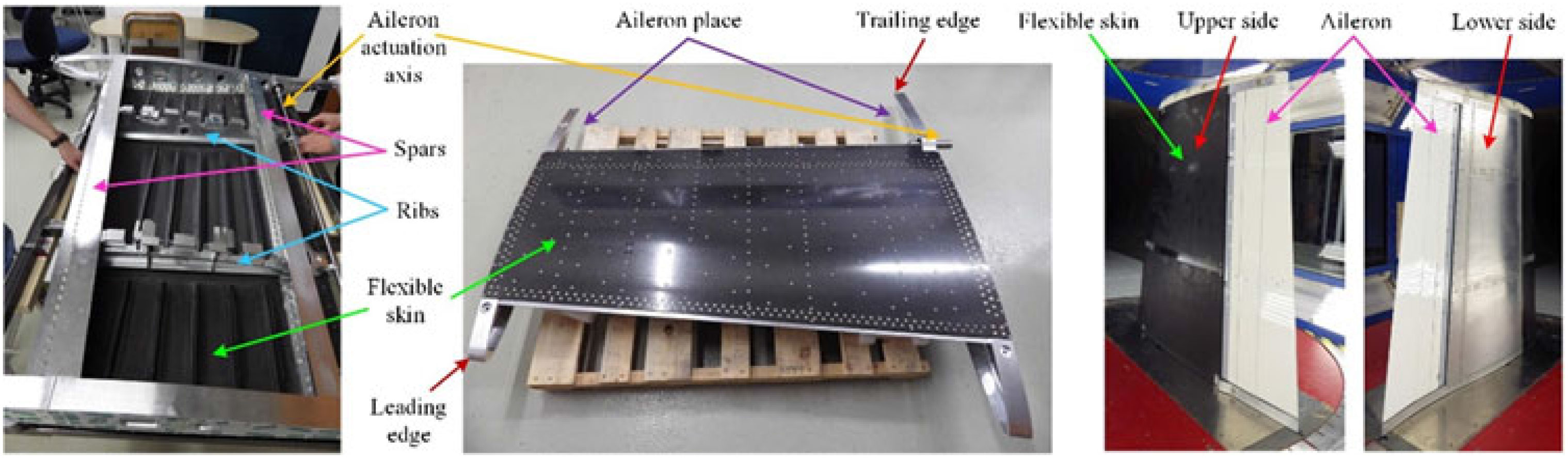
The designed and manufactured experimental model was a technical demonstrator of a real aircraft wing tip, being based on a full-scaled portion of a real wing equipped with an aileron. The entire internal structure of the demonstrator (including the spars and ribs) was designed and realised considering all structural constraints required by the original wing and imposed by industrial partners, while its dimensions were chosen to fit the dimensions of the IAR-NRC subsonic wind tunnel and force balance limitations (Fig. 1); the model resulted with a 1.5 m span and a 1.5 m root chord, including the aileron, with a taper ratio of 0.72 and a leading-edge sweep of 8°. It can be easily observed from Fig. 1 that the wing box and whole internal structure is made from aluminium, while the upper surface of the wing was equipped with a flexible skin manufactured in carbon fibre reinforced composite and delimited by the front and rear spars placed between 20% and 65% of the wing chord. To measure the pressure distribution over the wing, but also to record the airflow wave frequencies, 32 Kulite pressure sensors were placed on the flexible skin. The final configuration included a morphing aileron designed and manufactured by the Italian team(Reference Amendola, Dimino, Magnifico and Pecora34,Reference Arena, Amoroso, Pecora, Amendola, Dimino and Concilio35) .

Figure 1. Structure of the morphing wing experimental model.
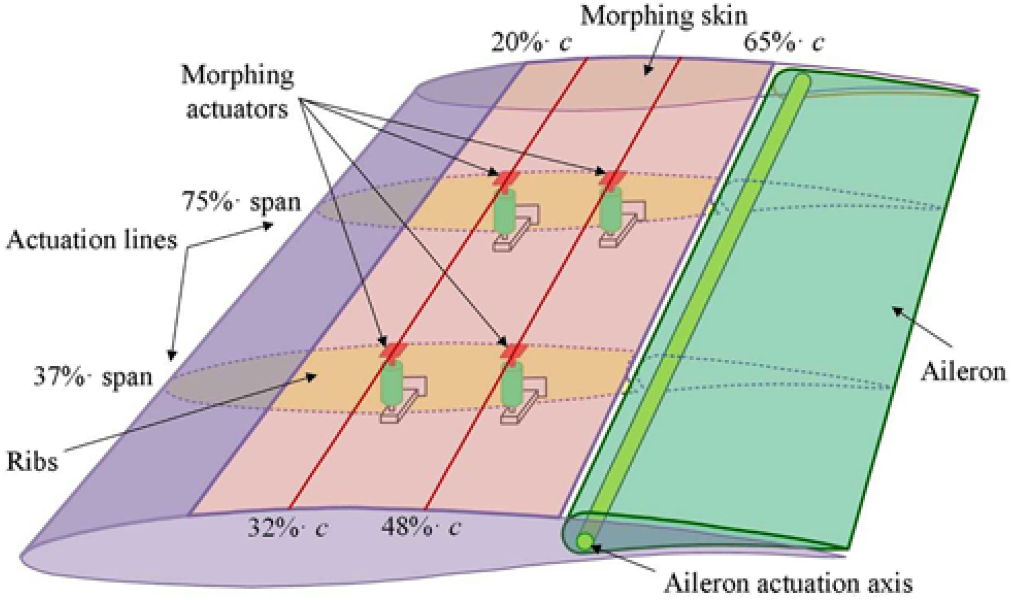
An aerodynamic numerical study was subsequently performed with the aim to optimise the morphed aerofoils for various flow cases, each one characterised by a Mach number (M), a wing angle-of-attack (α) and an aileron deflection angle (δ). In each flow case, the optimum shape of the aerofoil was searched by changing its local thickness in order to extend the laminar region of the upper surface flow(Reference Koreanschi, Sugar-Gabor and Botez36). The team decided to use two actuation lines installed in the sections at 37% and 75% of the wingspan and, on each one, two actuation points placed at 20% and 65% of the local wing chord. Therefore, to morph the upper surface of the wing, the actuation mechanism was based on four similar actuators placed as in Fig. 2 and fixed to the two central ribs of the wing.

Figure 2. Position of the actuators in the wing box.
The actuators need to perform a direct actuation of the flexible skin by pushing or pulling it until their controlled displacements equalled the desired ones provided by the aerodynamic study in each optimised flow case. The actuators were manufactured in our LARCASE laboratory at ETS, each of them included a Maxon brushless DC (BLDC) motor and a mechanism that converts the rotational actuation into a translational one. The linear actuation position for each actuator is monitored by using a linear variable differential transformer (LVDT) sensor that communicates with the actuator control system.
3.0 CONTROL SYSTEM TUNING PROCEDURE BASED ON PARTICLE SWARM OPTIMISATION (PSO) METHOD
To realise the improvement of laminar flow over the wing, the BLDC motor-based morphing actuator needs to be controlled in order to morph the wing until the skin displacements in the actuation points are the same with the aerodynamically predicted values for each studied flow case. As in all controlled systems design, after the understanding of the system behaviour and the establishing of control objectives, a necessary step is to obtain a simplified model of it. In the current situation, when a software based design procedure was targeted, both mathematical and software models were desired. The model included both the BLDC motor model and the model of the mechanism converting the BLDC motor rotational output in a translational output (Fig. 3)(Reference Khan, Botez and Grigorie37); its inputs are the DC bus voltage U and the load torque T load, while as outputs, it provided the electrical current I, the actuation speed v and the actuation linear position pos.
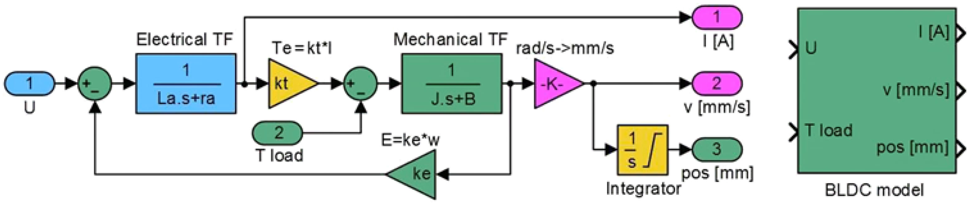
Figure 3. Model of the actuator implemented in MATLAB/Simulink.
The control of the actuation systems-based BLDC motors can be performed in many ways, including here classical control strategies, intelligent control strategies and various combinations between them. Also, the literature provides many methods to tune the coefficients of such control systems. The current paper shows the application of the PSO method to tune the coefficients used in the control system of our morphing wing actuator at the level of all three implied control loops: current loop, speed loop and position loop. To simulate the behaviour of the actuator, the BLDC model was integrated in the model in Fig. 4, where all three loops are highlighted. Also, in the simulation model, a cost function has been defined by taking the integral of the sum of squares of the position, speed and current control errors.
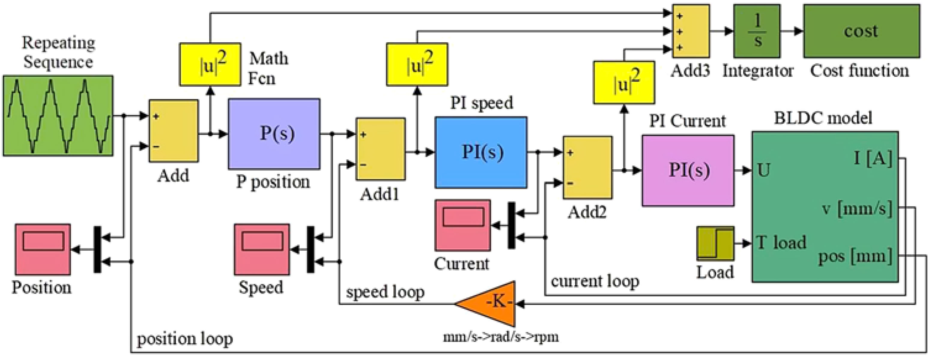
Figure 4. Simulation model used in the control system tuning-based PSO.
3.1 Particle Swarm Optimisation algorithm
PSO acts in a similar manner as the genetic algorithms, being a population-based algorithm that has been born from the study of the social behaviour of swarming insects, flocking birds and schooling fish. Each individual of this population is called a particle and, based on its own experience, it moves in steps with a specific speed in the direction of the location that provides the best resources. At the same time, this information is shared with the other members of the swarm, which are attracted to this location in a different degree. At the next step, based on the shared information between the members of the swarm, each particle re-evaluates its speed and direction, and this mechanism finally leads to the finding of the optimal location. From the PSO algorithm point of view, at each step, a cost function is evaluated, and a new speed and direction for the particle is decided. The technique was developed in 1995 by Dr Eberhart and Dr Kennedy(Reference Kennedy and Eberhart38) and further adapted and used in the optimisation procedures for many applications in aerospace engineering field.
A collaborative research team from NASA Langley Research Center and Vanderplaats Research and Development realised the optimisation of a transport aircraft wing using PSO; the optimisation problem was a bi-level one, with severe numerical noise and combining continuous and discrete variables, which restricted the use of gradient-based optimisation algorithms(Reference Venter and Sobieszczanski-Sobieski39,Reference Venter and Sobieszczanski-Sobieski40) . At the University of Naples in Italy, the PSO methodology application was tested in the field of conceptual design to define the preliminary configuration of an aircraft(Reference Blasi and Del Core41). A very interesting application is related to the space trajectory optimisation problem. A research team from the University of Illinois, USA, used PSO for the determination of periodic orbits in the context of the circular restricted three-body problem and for the optimisation of orbital transfers; the algorithm provided the optimal solutions with a very good numerical accuracy(Reference Pontani and Conway42). Also, researchers from NASA Johnson Space Center in Houston, USA, applied this methodology to optimise the entry flight path angle and reference trajectory for a modified Apollo guidance during Mars entry(Reference Grant and Mendeck43). Researchers from Concordia University in Montreal, Canada, applied PSO in the path planning for team(s) of unmanned aerial vehicles (UAVs) in fighting forest fires applications(Reference Ghamry, Kamel and Zhang44) and in the cooperative control of the multiple wheeled mobile robots(Reference Kamel, Yu and Zhang45,Reference Kamel, Yu and Zhang46) .
In a simplified approach, the mathematics of the algorithm can be described as follows: If the search space is N-dimensional, then each of the swarm particles has the form of a vector with N components(Reference Blasi and Del Core41)
 \begin{equation} X=(x_{1} ,\; x_{2} , \ldots, x_{N} ),\end{equation}
with the speed expressed as(Reference Blasi and Del Core41)
 \begin{equation} V=(v_{1} ,\; v_{2} , \ldots, v_{N} ).\end{equation}
At each discrete step time (k + 1), the speed of the variable x i characterising the particle X is updated by using the formula(Reference Blasi and Del Core41)
 \begin{equation} v_{i} (k+1)=w(k)v_{i} (k)+c_{1} \rho _{1} (k)[p_{l,i} (k)-x_{i} (k)]+c_{2} \rho _{2} (k)[p_{g,i} (k)-x_{i} (k)],\end{equation}
where w is the inertial weight, p l,i(k) is the value of the variable x i reflecting the particle best position (local optimum), p g,i(k) is the value of the variable x i reflecting the population best position (global optimum), c 1 - the cognitive parameter, c 2 - the social parameter and ρ 1 and ρ 2 are random variables generated with values between 0 and 1. The new value of the variable x i results with equation
 \begin{equation} x_{i} (k+1)=x_{i} (k)+v_{i} (k+1).\end{equation}
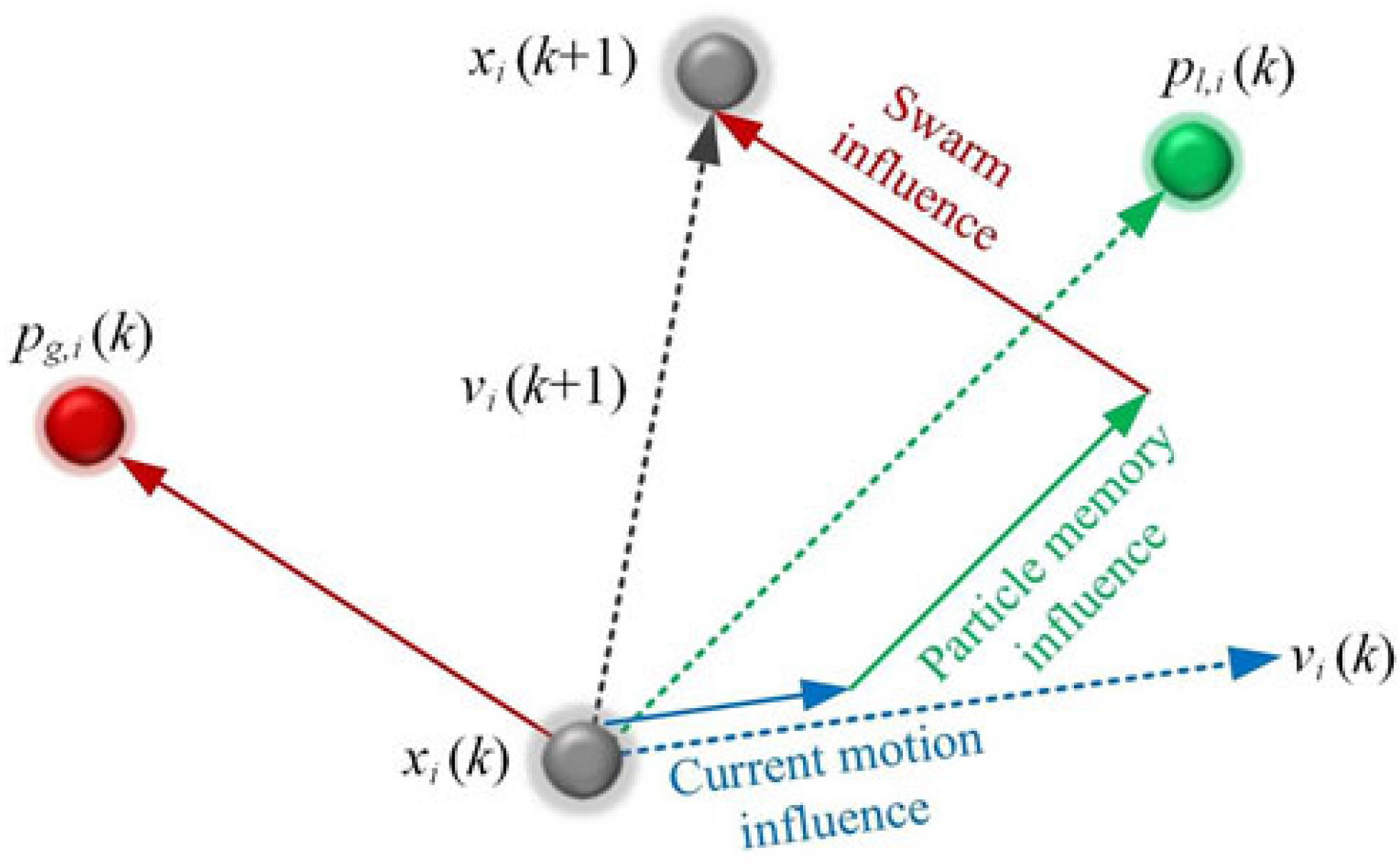
Choosing the proper values for the c 1, c 2 and w parameters makes the algorithm more efficient. The literature survey suggested some limits for these values: 0 < c 1, c 2 = 2 and 0.8 = w = 1.4(Reference Blasi and Del Core41–Reference Grant and Mendeck43,Reference Hassan, Cohanim and de Weck47–Reference Poli, Kennedy and Blackwell49) . The velocity and position updates in the PSO algorithm can be schematised as in Fig. 5(Reference Hassan, Cohanim and de Weck47), while, according to the exposed mechanisms, the flow chart of the PSO algorithm results as in Fig. 6.

Figure 5. The velocity and position updates in PSO algorithm.
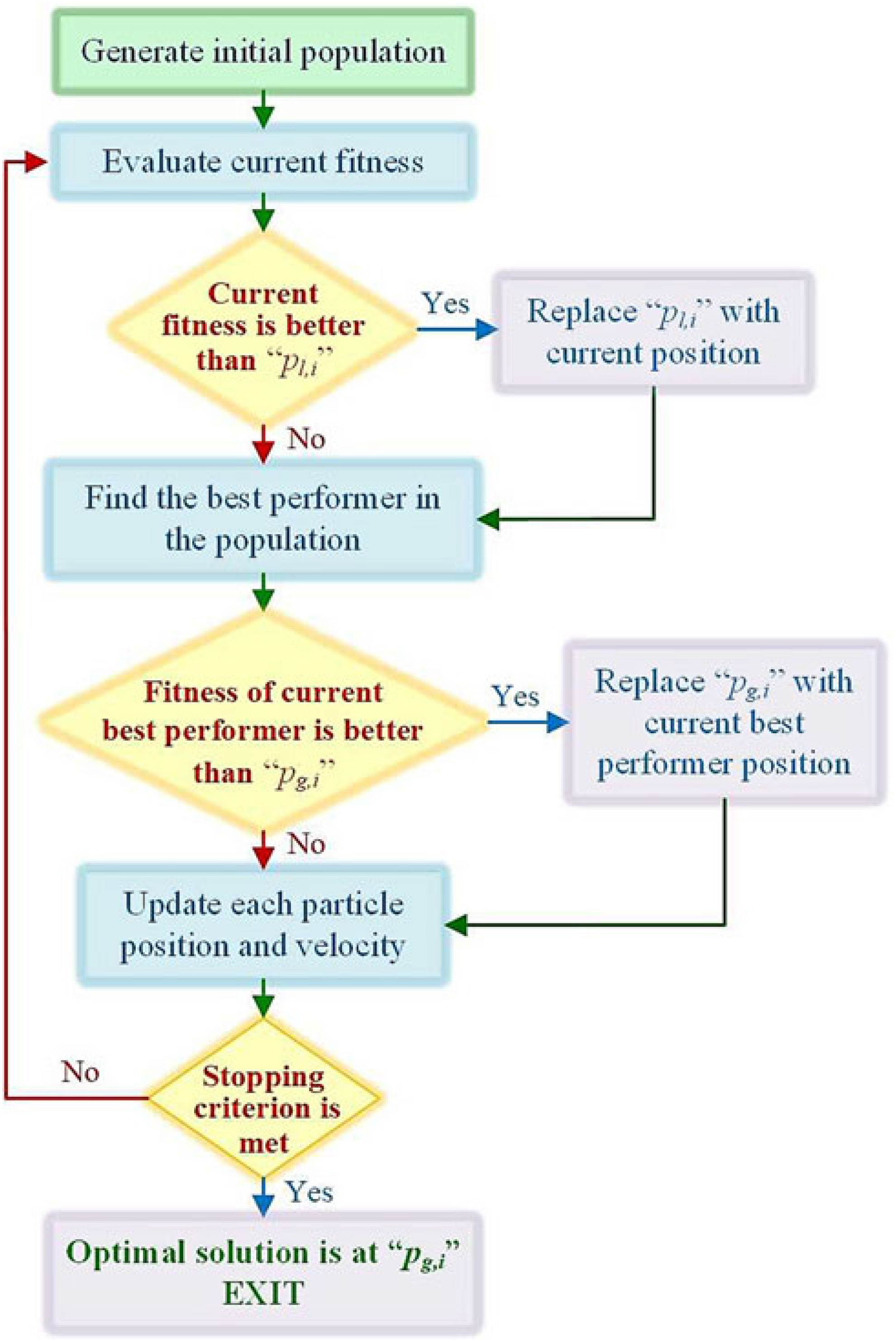
Figure 6. Flow chart of the PSO algorithm.
3.2 Control system tuning
According to the model presented in Fig. 4, the control system that is desired to be tuned includes three loops (current loop, speed loop and position loop), which supposes the presence of five control coefficients, three proportional gains and two integral gains: K Pp – proportional gain for Proportional (P) position controller; K Ps – proportional gain and K Is – integral gain for Proportional-Integral (PI) angular speed controller; K Pc – proportional gain and K Ic – integral gain for Proportional-Integral (PI) electrical current controller.
To tune the control system used for the morphing wing actuators, the PSO algorithm has been implemented in a MATLAB software subroutine working in conjunction with the simulation model of the controlled actuation system presented in Fig. 4. The code flow of the PSO algorithm for our system is shown in Fig. 7.
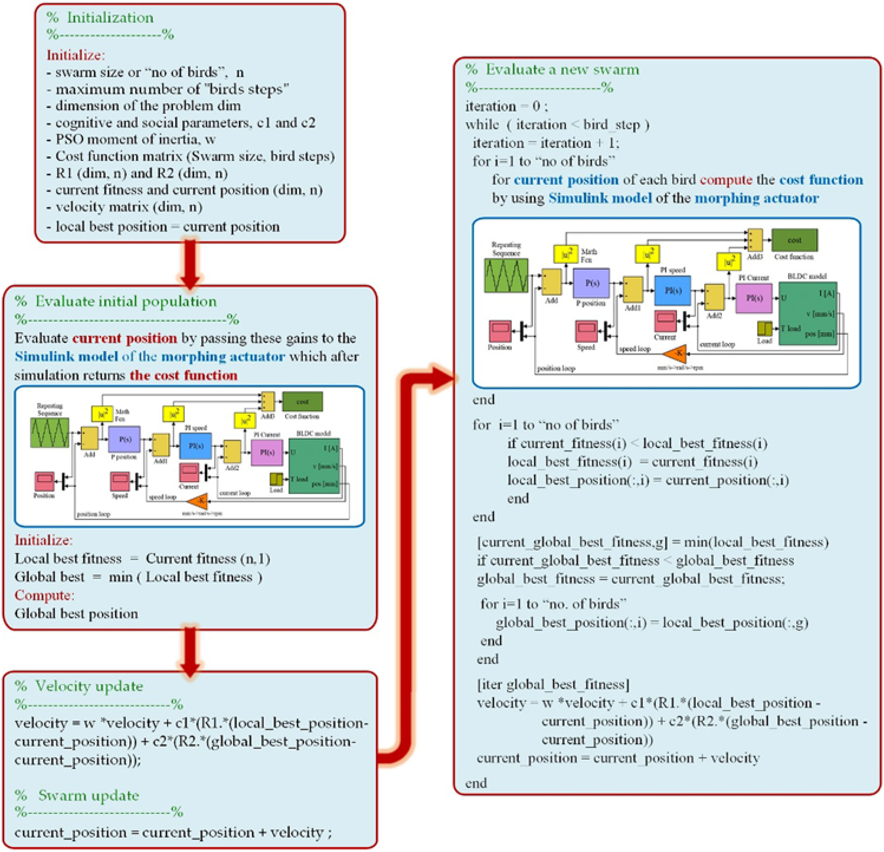
Figure 7. The PSO algorithm code flow for our optimisation case.
The optimisation procedure ran for various combinations of the three weight factors, w, c 1 and c 2, with values between 0.1 and 2.2 for c 1 and c 2, and between 0.1 and 1.9 for w, taken with a step of 0.1. Also, during the optimisation, various values were considered for the swarm size (‘number of birds’), 10 and 20, but also for the maximum number of ‘bird steps’, between 10 and 100, taken with a step of 10. For the ‘initialisation’ of the control system, five coefficients and two variants were used. In the first variant, the initial coefficients were generated as random numbers in the vicinity of the gains derived by our team by using a classical tuning method(Reference Khan, Botez and Grigorie37), while in the second variant, the ‘randi’ MATLAB function was used to generate the coefficients in the range of 1 to 40,000. The best results were obtained for a swarm size of 20 ‘birds’, with a number of 50 ‘bird steps’ and with c 1 = 1, c 2 = 1.2 and w = 0.9. The cost function was found, in this case, with the value of 2.8424·105, while the optimised control gains were: K Pp = 42354, K Ps = 1.2, K Is = 0.005, K Pc = 207 and K Ic = 34025.
Table 1 presents a few cases evaluated during the optimisation process with the associated results, while Fig. 8 shows the variation of the cost function vs number of iterations for these cases; Case #11 in the table presents the parameters of the optimal situation. The controlled actuator answers to a position step input as a required signal for the optimised values of the coefficients and is shown in Fig. 9 for position, speed and current loops. Also, a numerical simulation run for the optimal case, having a position input of a complex signal with positive and negative ramps connecting different horizontal levels considered between −3 mm and 3 mm, provided the results in Fig. 10. Figure 10 also shows the position, speed and current control results. Simulation results confirm that the actuator control system performed very well, with a rise time of approximately 2 s for a unitary step input in position and with no overshoot.
Table 1 Parametric study of PSO for morphing wing actuator control: examples

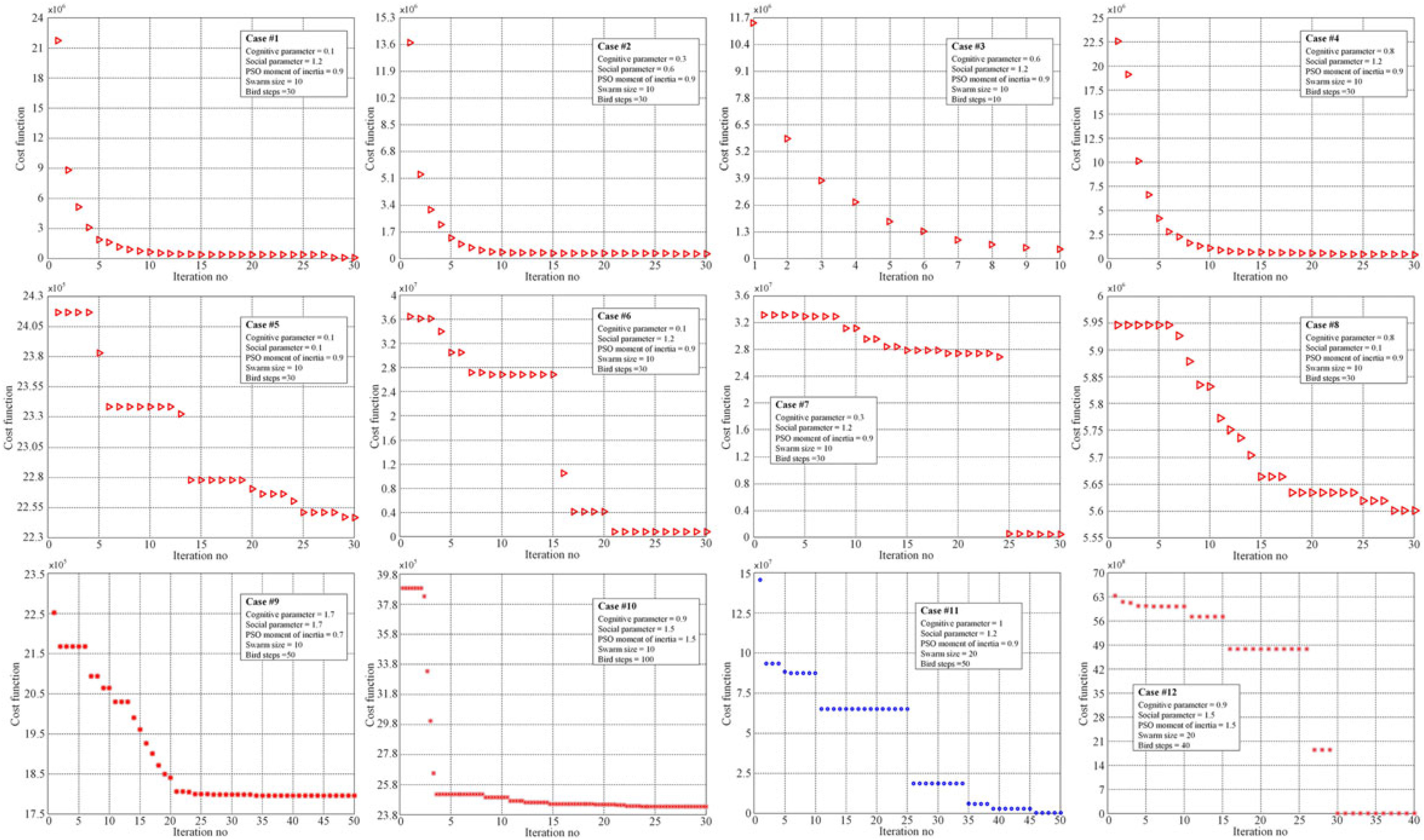
Figure 8. The variation of the cost function vs number of iterations for the cases in Table 1.
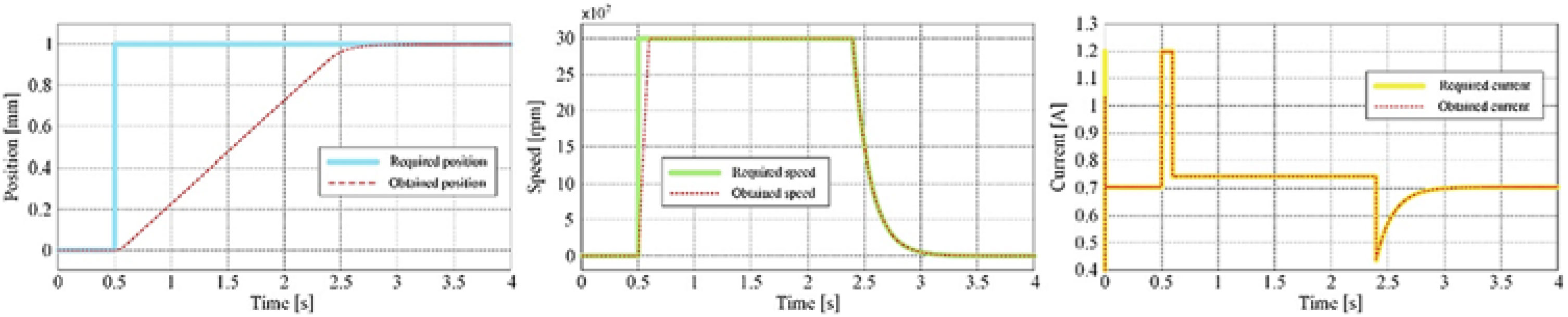
Figure 9. The controlled actuator answers to a position step input as required signal.
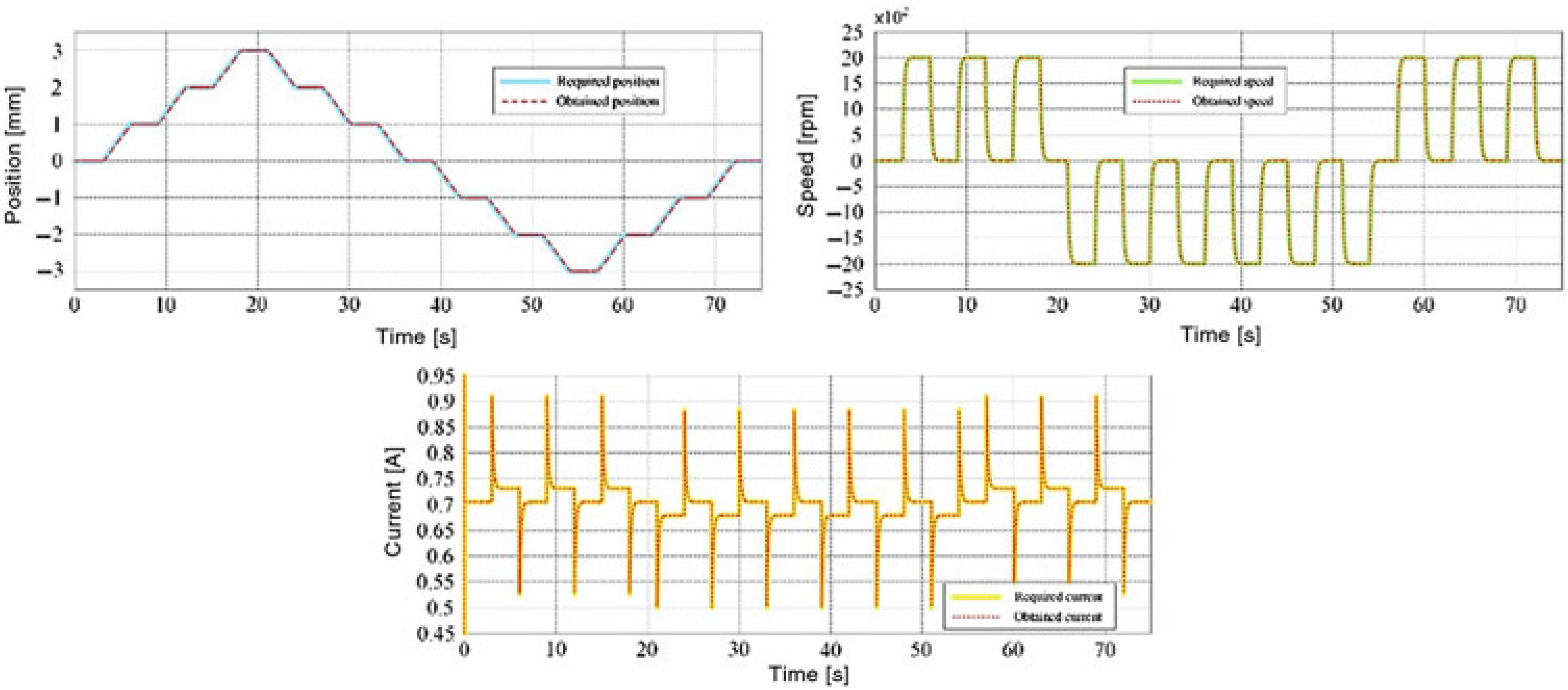
Figure 10. The controlled actuator answers to a complex signal input in position.
4.0 EXPERIMENTAL INSTRUMENTATION OF THE MORPHING WING MODEL AND WIND-TUNNEL TESTING
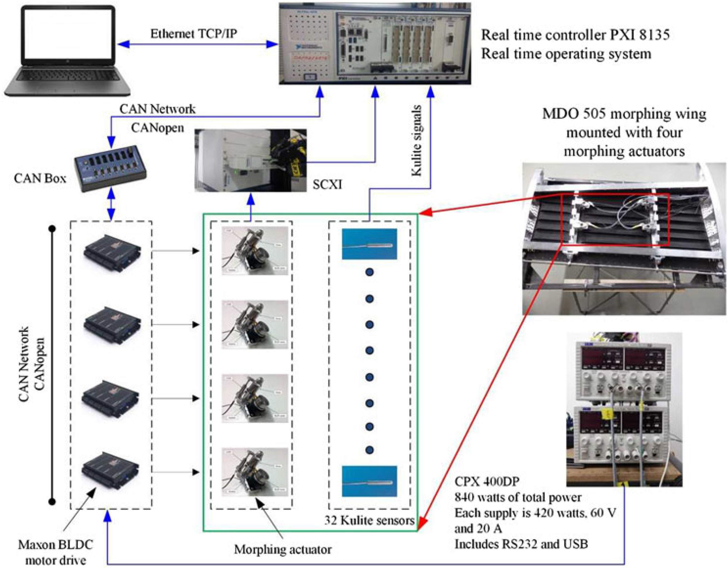
The aim of the experimental instrumentation was to integrate the morphing wing system, as a whole, with a well-controlled actuation system but also with pressure sensors for airflow monitoring and corresponding software for data processing and decisions making. The equipment used to integrate the morphing wing system has been configured as in Fig. 11.

Figure 11. Equipment configuration for the morphing wing experimental model.
The real-time controller, is a PXI 8135 controller with a 2.3 GHz Intel Core i7 embedded controller, which runs a real-time operating system, and is linked to the host through an Ethernet connection managed by a TCP/IP protocol. The controller was connected to various input and output modules as shown in Fig. 11. The four morphing actuators were controlled by using EPOS2 24/5 Maxon drives connected to the PXIe controller via a CAN breakout box, which in turn was connected to the CANopen interface module. This module can transmit/receive process data objects and service data objects with a speed of up to 1 Mbits/s. The EPOS 24/5 drives are built with several communication interfaces, both analogue and digital, and can connect as slaves in a CAN network via a CAN interface on the device. The drives perform the electronic commutation of the BLDC motor based on the feedback from Hall sensors. The regulation architecture is based on the current, speed and position loops, the devices allowing the programming of the control coefficients inside them through NI-Veristand CANopen custom devices. NI-Veristand software is used for the real-time applications made up of three modules: project file, system file and the screen file. The system definition file contains the configuration settings of the NI-Veristand engine, which consist of target rate, hardware (DAQ, FPGA, etc.), custom devices, models system mappings, etc. System explorer window of the system definition contains the target, which can be added by the user.
Once integrated, the controlled experimental morphing wing model was tested and calibrated on bench, under lab conditions, with no airflow load and then sent to the IAR-NRC subsonic wind tunnel for the final testing. The wind-tunnel testing treated the system as a whole and included, besides the evaluation of the controlled actuation system, the testing of the integrated morphing wing experimental model and the evaluation of the aerodynamic benefits brought by the morphing technology on this project. From this last perspective, the airflow on the morphing upper surface of the experimental model was monitored by using various techniques based on pressure data collection with Kulite pressure sensors or on infrared (IR) thermography camera visualisations. Ninety-seven flow cases, numerically optimised previously, were run and evaluated during the wind-tunnel testing, both in original configuration (non-morphed) and in optimised configuration (morphed), with the actuation system controlled in such a way that the controlled displacements equal the desired ones provided by the aerodynamic study in each optimised flow case.
Besides the real-time monitoring and visualisation of the airflow characteristics by using an in-house developed graphical user interface (GUI), for both configurations in each flow case, a post-processing and analyse stage of the acquired data has been performed and conclusions drawn. The processing of pressure sensors aimed at the estimation of the position for the laminar to turbulent airflow transition in the pressure sensors station (a 2D estimation) was based on Fast Fourier Transform (FFT) and on the Standard Deviation (SDT) evaluation. Also, a post-processing action and a detailed analysis has been performed for the IR captures to estimate the position for the laminar to turbulent airflow transition over the entire upper surface of the morphing wing (a 3D estimation).
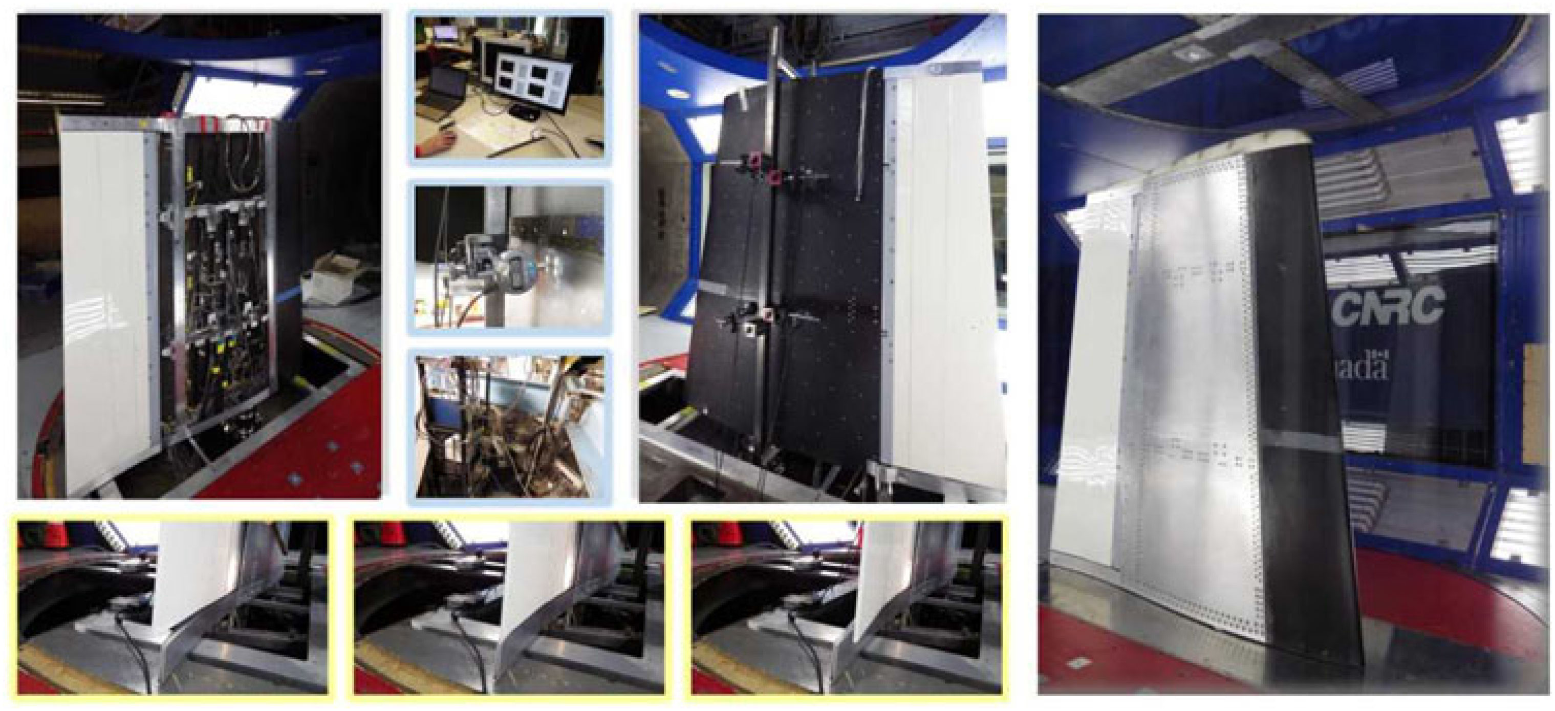
As an example, Fig. 12 exposes the results of the scanning performed in the LARCASE laboratory during the calibration of the integrated system for the case characterised by M = 0.15, α = 0.25° and δ = 0° flow conditions. Figure 12 only shows the scan of the wing upper surface, without the aileron. The four required actuation distances were: −.27 mm, 2.14 mm, −1.37 mm and 2.33 mm. Also, few calibration tests were performed in the National Research Council of Canada wind-tunnel testing facility in Ottawa, when the model was added in the testing room (Fig. 13). The corrections obtained during the calibration procedures were included in the application software component and taken into consideration during the wind-tunnel tests.
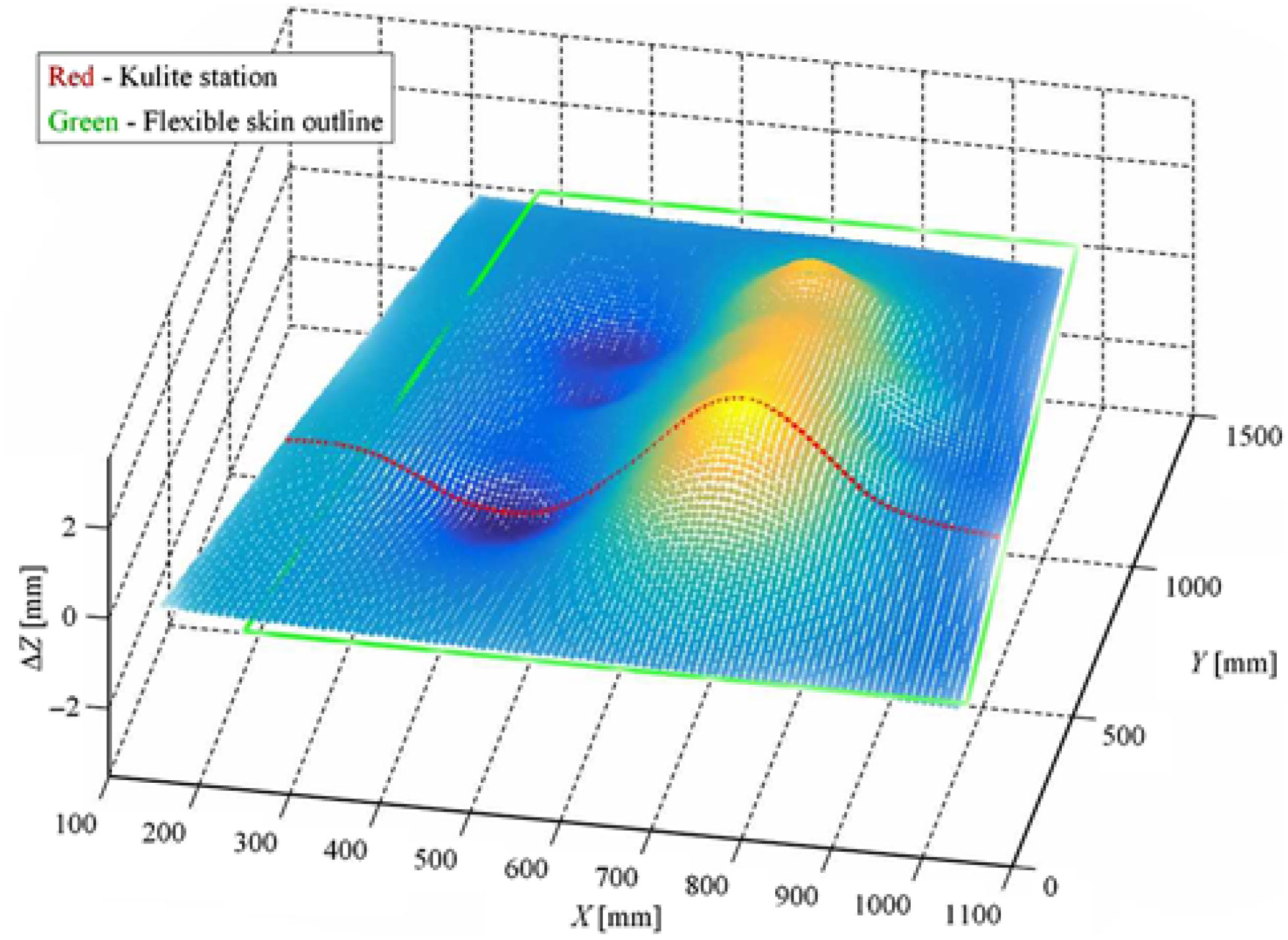
Figure 12. Calibration scanning on bench for M = 0.15, α = 0.25° and δ = 0° flow conditions.

Figure 13. Model installation and calibration in the NRC wind tunnel.
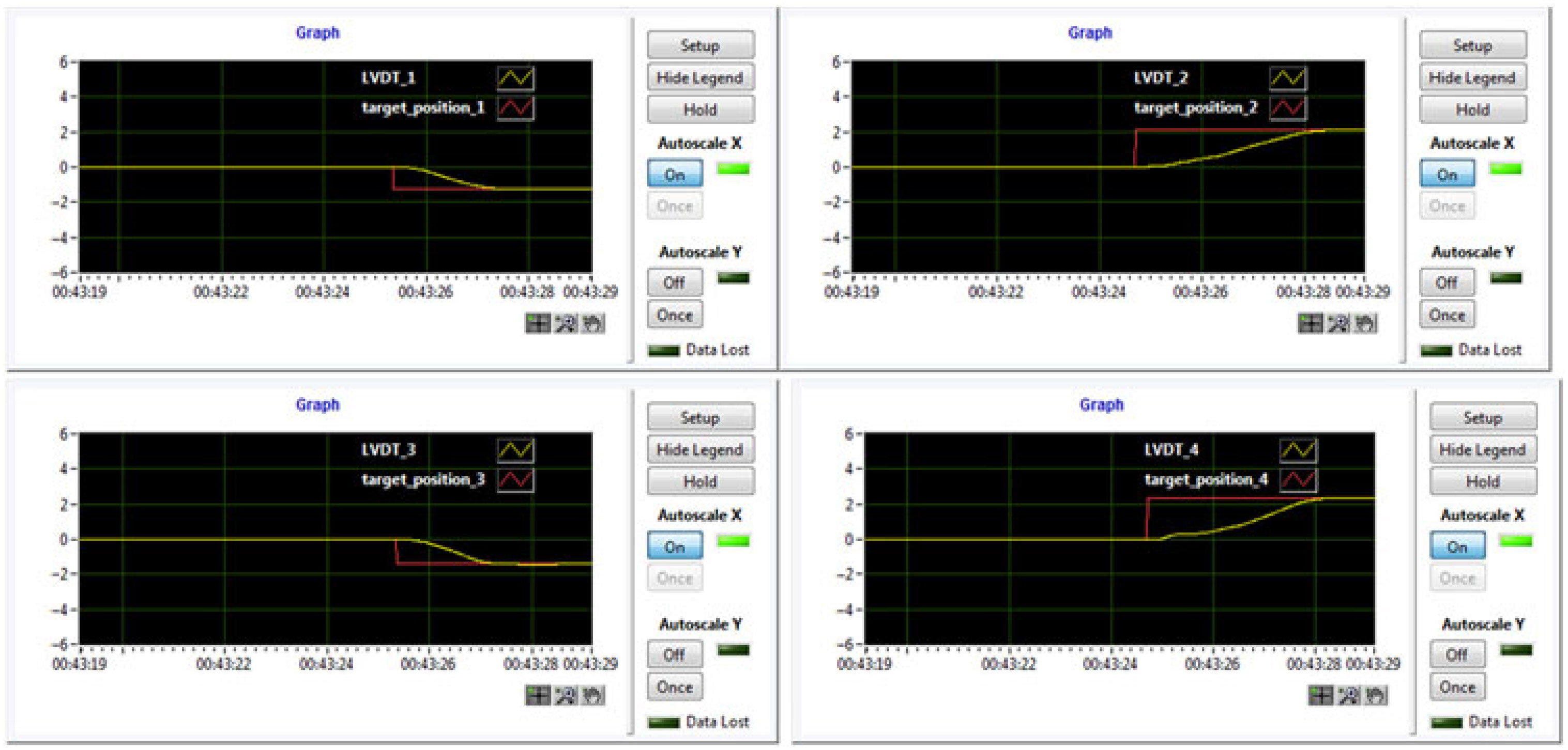
From the developed GUI, the picture in Fig. 14 was obtained describing the actuation results during the wind-tunnel test for the morphed configuration of the wing in the same flow case. It can be easily observed that the controller performed very well in the wind-tunnel conditions with aerodynamic load. On the other hand, the IR thermography technique provided the pictures in Fig. 15, presenting the IR captions for the un-morphed and morphed configurations and the 3D estimation for the position of the laminar to turbulent airflow transition over the entire upper surface of the morphing wing. The IR pictures were obtained during the first of the three wind-tunnel tests.

Figure 14. The actuation results during the wind-tunnel test for M = 0.15, α = 0.25° and δ = 0° flow conditions.

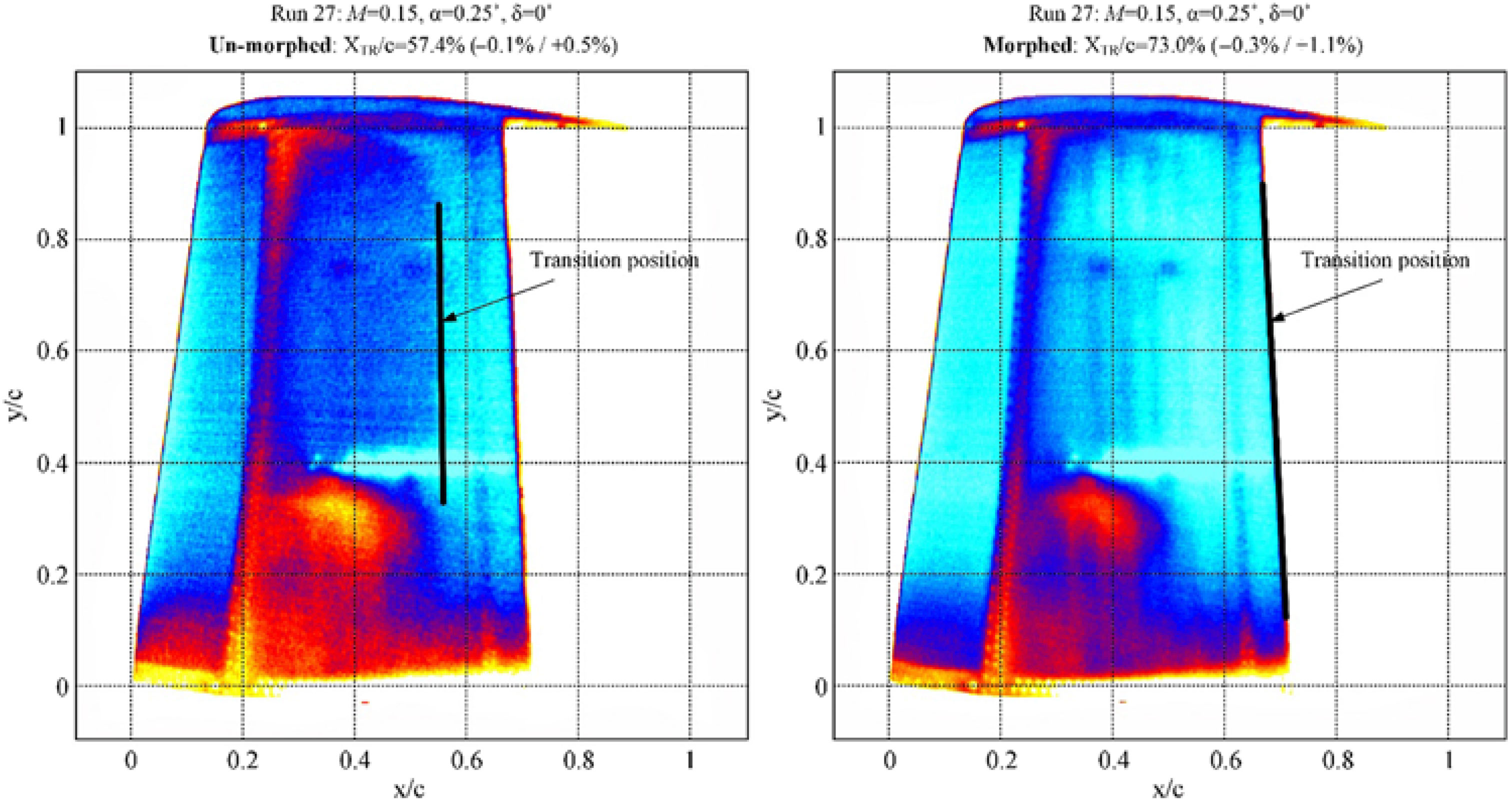
Figure 15. IR caption of the transition region for M = 0.15, α = 0.25° and δ = 0° flow conditions.
According to the results presented in the first picture of Fig. 15, the mean value estimated for the position of the laminar to turbulent airflow transition over the entire wing upper surface in the original (un-morphed) configuration was 57.4% of the wing chord, with an error between −0.1% and +0.5%. The interpretation of the results exposed in the second picture of Fig. 15, for the morphed configuration of the wing, locate the transition at 73.0% of the wing chord (with an error between −0.3% and +1.1%) in the area of the wing conjunction with the aileron.
Therefore, the improvement brought by the morphing technology in this flow case (M = 0.15, α = 0.25° and δ = 0°), calculated as the difference between the mean values estimated for the position of the laminar to turbulent airflow transition over the entire wing upper surface for the morphed and the original (un-morphed) configurations, is 73.0% − 57.4% = 15.6% of the wing chord.
During all three wind-tunnel tests, the project research team observed that all three mechanisms used to estimate the airflow transition position (FFT, STD and IR) provided similar estimates related to the Kulite sensors span-wise station, both for original (un-morphed) and morphed configurations, validating in this way the airflow’s IR thermography analysis performed for the whole surface of the wing. Also, the team observed that the morphing technology improved the mean position of the laminar to turbulent flow transition over the whole wing (the difference between the mean values estimated for the position of the laminar to turbulent airflow transition over the entire wing upper surface for the morphed and the original (un-morphed) configurations with more than 2.5% of the wing chord for the great majority of the wind-tunnel tested flight cases).
5.0 CONCLUSIONS
Shown in this paper was a part of the work done during a major morphing wing research project exploring the improvement possibilities for the aerodynamics of a full-scaled portion of a real wing. The main presented contributions referred to the design of the control system used in the morphing wing application and to the experimental testing of the developed physical model for the morphable wing. The morphing actuation system included four similar miniature actuators placed inside the wing and based on four BLDC motors. The actuators were developed in-house by the research team in such a way that they were able to execute a direct actuation of the flexible upper surface of the wing.
The tuning algorithm for the control system of this actuation system was based on the PSO method. In recent heuristic search methods, PSO is one of the methods that takes inspiration from the collaborative behaviour of the biological population or swarming. The obtained control coefficients were tested with very good results, both through numerical simulations and experimentally, in bench tests and wind-tunnel tests, together with all components of the developed experimental model of the morphing wing. The wind-tunnel testing considered not only the evaluation of the controlled actuation system, but also the testing of the integrated morphing wing experimental model and the evaluation of the aerodynamic benefits brought by the morphing technology on this project.
The evaluation of the model from the perspective of the aerodynamics improvement implied the monitoring of the airflow on the morphing upper surface of the experimental model. Various techniques were used in this way: the acquisition of the pressure data provided by some Kulite pressure sensors and their processing based on FFT and on SDT evaluation and IR thermography camera visualisations. The FFT and SDT techniques provided a 2D estimation of the position for the laminar to turbulent airflow transition in the pressure sensors station, while the IR technique provided a 3D estimation of this position.
The results obtained during the wind-tunnel testing proved that the morphing technology is one of the most promising technologies for the improvement of the aircraft aerodynamics, providing a method of fuel consumption reduction for the next generation of aircraft. The research team observed that the morphing technology improved the mean position of the laminar to turbulent flow transition over the whole wing (the difference between the mean values estimated for the position of the laminar to turbulent airflow transition over the entire wing upper surface for the morphed and the original (un-morphed) configurations) with more than 2.5% of the wing chord for the great majority of the 97 tested flight cases.
ACKNOWLEDGEMENTS
The authors would like to thank the Thales team for their support, with special thanks to Mr Philippe Molaret, Mr Bernard Blouin and Mr Xavier Louis, and the Bombardier Aerospace team – Mr Patrick Germain and Mr Fassi Kafyeke for their help and fruitful discussions. We would also like to thank Bombardier Aerospace, Thales, and the Consortium for Research and Innovation in Aerospace in Quebec (CRIAQ) and the National Sciences and Engineering Research Council (NSERC) for the funding received in connection with the CRIAQ MDO 505 project.