NOMENCLATURE
- W
Weight
- E
Aerodynamic Efficiency
- TOW
Take-off weight
- β
Actuator shaft rotation
- δ
Angle between R and Force
- φ
Actuated Rib morphing angle
- γ
Relative Angle between block B2 and block B1
- F
Force trasmitted from the actuator to the guide
- L
Distance between actuator shaft and rib rotation hinge
- MA
Mechanical Advantage
- I.C.
Istantaneous Centre
- SMA
Shape Memory Alloy
- Matt
Actuation Torque
- α
Wing Angle of Attack
- ε
Rigid Aileron deflection
- MPC
Multi Point Constraint
- R
Crank dimension
- VLM
Vortex Lattice Method
1.0 INTRODUCTION
Wing shape morphing is a promising area of research that may offer substantial improvements in aircraft aerodynamic performance. The concept of morphing may aim at a large number of targets, and its assessment strongly depends on the final objectives and the components where it has to be deployed. Maneuver, take-off, landing, cruise conditions, just to cite few and very general examples, all have their own peculiarities; the wing shape change has to suit on. Indeed, the current design of multiple aerodynamic devices (such as flaps and slats) hides a simplified primary idea of morphing. Such conventional hinged mechanisms are effective in controlling the airflow, but they are poorly efficient because of the structural discontinuities which degrade aerodynamic performance, as mentioned by(Reference Barbarino, Bilgen, Ajaj, Friswell and Inman1), yet so important to keep the stream attached and decrease the wake drag. The idea of developing compliant flaps is controversial because they would be able to undergo lower angles of attack while increasing their point performance. Such innovative flaps would be moreover confined to increase the local curvature and not to enlarge the original chord. However, cruise is the typical mission segment of a generic commercial aircraft that presents the optimal characteristics to request implementing a device aimed at increasing curvature without showing any gap whose effect would cause great damages at those speeds. In fact, airplane weight reduces up to 30% during a long-range mission due to fuel consumption(Reference Ahrend, Heyland and Martin2,Reference Monner, Sachau and Breitbach3) . In the field of morphing structures it is very meaningful to report the works conducted by(Reference Ursache, Melin, Isikveren and Friswell4,Reference Woods, Gentry, Kothera and Werleley5) , who lead several research projects related to the development of innovative adaptive devices, for instance morphing winglet and also projects about actuation systems such as pneumatic muscle for trailing edge. Moreover, in(Reference Vasista, De Gaspari, Ricci, Riemenschneider, Monner and van de Kamp6) is investigated a morphing compliant architecture in alternative to the rigid mechanism for droop-nose wingtip. Such important structural modifications can be compensated by a limited wing camber to obtain a near optimum geometry in order to guarantee a minimal distance from the optimal aerodynamic shape. The most obvious way to realise this target is to develop an adaptive trailing edge. In this sense, many researches dealing with chord-wise and span-wise either synchronous or differential continuous (i.e., no gapped) camber variations can be found in literature. In particular, authors in(Reference Hilibig and Wagner7) described that wing camber variation often concerns trailing edges because of the highly associated L/D ratio enhancements. The basic idea is to add a system that can modulate the local airfoil aspect to follow the aircraft weight variations. A major difficulty in the development of morphing devices is to reach an adequate compromise between high load-carrying capacity to withstand aerodynamic loads and sufficient flexibility to achieve the target shapes on the other. These targets necessitate the use of innovative structural and actuation solutions. Since the 1980s several morphing programs were launched. NASA and USAF proposed the AFTI (Advanced Fighter Technology Integration)/F-111 program with the main purpose to integrate, on board a military aircraft, a wing camber morphing. The resulting mission-adaptive wing (MAW), described by(Reference Powers, Webb, Friend and Lokos8), consisted of a trailing edge and leading edge, variable camber control surfaces that could be deflected during flight to provide a near-ideal wing camber shape for any flight conditions. In(Reference Ippolito, Nguyen, Totah, Trinh and Ting9) is presented an initial assessment of a new numerical model of a variable continuous trailing-edge flap (VCCTEF) system on a commercial transport-class fixed-wing aircraft in subsonic cruise. The VCCTEF system offers potential pay-off for drag reduction by active aeroelastic shape control by means of SMA actuators. Authors in(Reference Joo, Marks, Zientarski and Culler10) developed a novel adaptive Variable Camber Compliant Wing (VCCW) that can actively re-contour the airfoil camber using compliant mechanisms. A VCCW with distributed camber control would be able to reconfigure itself through the continuous deformation of the structure to optimise its geometry to suite the current altitude, airspeed, and lift-to-drag (L/D) ratio requirements. In addition, the possibility to avoid unwanted aerodynamic flows such as separated and increased parasitic drag is also carried out by means of seamless skin. Holes and gaps were, in such a manner, removed. In the presented study it targeted the use of the aileron as an added adaptive element to modify the wing shape to match different flight conditions (for instance, compensate the weight reduction), extending “adaptive flaps” capability (Reference Concilio, Dimino, Ciminello, Pecora, Amoroso and Magnifico11,Reference Dumont12) ). It is expected that the use of morphing aileron can increase by the 10% the advantage of having a morphing flap for cruise adaptation (3.0–6.0% to 3.3–6.6%), by acting over a small segment of the wing span. Furthermore, from literature studies (Reference Wolcken and Papadopoulos13), it clearly emerges that generally a three-hinged system almost doubles the efficiency with respect to a single-hinged one for adaptive aerodynamic surfaces. Therefore, a morphing aileron (in perspective, fully deformable) should have a better efficiency than a usual single-slotted one. It is worth to remark that the traditional functionality of the aileron is preserved (the main hinge is not removed). Because the augment morphing capability, the control roll authority may be also improved (added degrees of freedom).
When dealing with adaptive structures for lifting surfaces, the level of complexity naturally increases as a consequence of the augmented functionality of the designed system. An adaptive structure ensures a controlled and fully reversible transition from a baseline shape to a set of different configurations, each one capable of withstanding the associated external loads. To this aim, a dedicated actuation system shall be designed. In addition, the adopted morphing structural kinematics shall demonstrate complete functionality under operative loads. An actuation system specifically developed for these scopes is presented by(Reference Dimino, Flauto, Diodati, Concilio and Pecora14). It is based on a lever mechanism driven by load-bearing actuators which combine load carrying and actuation capacities. Such an actuation architecture allows the control of the morphing structure by using a reduced mass, volume, force and consumed power with respect to conventional solutions. In that case, the study focused on the inner and medium wing regions, the parts where flap systems are generally located. The aim was to set up an add-on device to a limited segment of the local flap chord to exploit its functionality in cruise while preserving the usual capability during take-off and landing. That successful development was worth further investigation in order to understand its applicability to the whole wing span. It means to verify the applicability of those concepts to the aileron region. During the design phase, many challenges were encountered, which make the device very different and innovative with respect to the previous concepts. The aileron geometry is characterised by very low thickness, which makes necessary to conform the flap actuation system architecture to a reduced available room. As consequence, the aileron is not uniformly actuated, and it is subjected to a different actuation forces distribution due to a non-symmetric configuration. The tip bays (the thinnest) worked as slave of the active segments. In other words, only a few bays hosted actuator systems. This differs from the previous configuration where each single bay was directly driven, leading to a stiffness increase. The aileron is also a safety-critical control surface, which failure could be catastrophic for the airplane. In such a manner, the aileron design was conducted also with the support of a preliminary FHA (Functional Hazardous Analysis) described by(Reference Arena, Noviello, Rea, Amoroso, Pecora and Amendola15). These steps forced the authors to perform a further innovative approach to the morphing wing systems design, providing new insights in the behavior of this kind of structures. In future research projects, a more detailed failure analysis shall be conducted where the aileron runaway probability will be estimated. Because the aileron region is a very delicate zone, where aeroelastic phenomena may be very important following the very reduced local structural stiffness and the complex aerodynamic field, a dedicated preliminary flutter analysis was conducted in parallel with the structural design of the wind tunnel demonstrator in order to avoid instabilities. Morphing ailerons may be a tough target because of the aeroelastic effects that can be caused by adding further degrees of freedom. In this sense, this paper is a first approach to that problem, envisaging extensive aeroelastic studies to prove the actual feasibility of the proposed solutions. Detailed studies, involving the whole wing architecture, will be part of the next researches. In this work, a linear-guide-based actuation concept is presented to actuate a so-called “morphing aileron.” The general architecture resembles the same philosophy as developed for the flap. A further device is added to an original aileron system. It is aimed at working in cruise to modify a limited chord segment of the aileron, so to accomplish the aircraft weight variations following fuel consumption. However, during classical manoeuver, this morphing, no-gap part is rigid, and the aileron works in the usual manner. The system is therefore made of two motor systems, one devoted to manoeuver and other classical aileron employments, whereas the other is devoted to the implementation of morphing. Such a morphing device wants to augment the former device expanding the hosting wing region by adapting local wing camber shape and lift distribution through a quasi-static deflection its excursion ranging into few unit of degrees, positive and negative. The developed device has a lot of further potentialities, that will be the object of further works and publications and that are currently explored by the authors; for instance, by giving it a large bandwidth, it could be used as an additional load alleviation device for the outer wing in order to reduce peak loads for gusts. The study is conducted in the framework of the CRIAQ MD0-505(16) project which promote a cooperation between Canadian and Italian partners from the aeronautical research and industrial field. The present work is mostly aimed at the preliminary numerical verification and design of the actuation system. In fact, the analyses were carried out only on one isolated leverage while in future studies the actuation system will be validated entirely with the aileron structure. Linear and non-linear static analyses were carried out to assess the structural solicitation and forces. The kinematic analytical model was validated with a multi-body simulation and the results compared. The external hinge moment was applied to the structure and the vertical force acting on the linear guide carriage was estimated as reaction loads under the hypothesis of glued contact among the sliding part and the rail. Moreover, at the end of the analyses, the first leverage arrangement was discarded, and a new configuration was then adopted and additionally investigated.
2.0 THE CONTEXT
A self-contained morphing device, made of links, hinges and joints to alter the inner geometry, is developed with the purpose of providing a standard hinged control surface with an added functionality which may improve aircraft off-design points, such as cruise or climbing. However, similarly to any promising technology to be integrated into aircraft, an estimation of the weight loss or gain is essential with respect to the original configuration, yet not accurate. On the one hand, according to Breguet’s formula, aircraft range strictly depends on aircraft aerodynamic efficiency and the ratio between the maximum take-off weight and the burned fuel weight. On the other hand, it is evident that the benefits associated with morphing in terms of aerodynamic efficiency shall be high enough to compensate for the drawbacks coming from possible structural weight increment. Therefore, in order to gain competitive advantages through morphing devices, it is necessary that, conceptually:
 $$\Delta W_{fuel}^E {\rm{ > }}\Delta TOW$$
(1)
$$\Delta W_{fuel}^E {\rm{ > }}\Delta TOW$$
(1) where
 $$\Delta W_{fuel}^E $$ generically indicates the saved fuel weight due to the aerodynamic efficiency (apex E) increment for the effect of the morphing device. ΔTOW is the aircraft maximum take-off weight increment due to the use of the morphing aileron. The herein designed morphing aileron was derived from the previous conventional aerodynamic surface, mounted on a 78-seat aircraft. Its final weight approaches 25 kg. With the aircraft maximum weight around 20 tons, it comes up that the morphing aileron is only 0.13% of the entire aircraft weight. In light of this consideration, the results show that the weight penalty could be easily compensated by the fuel savings ensured by such a morphing technology. During SARISTU project (Reference Carossa, Ricci, De Gaspari, Liauzun, Dumont, Steinbuch, Wölcken and Papadopoulos17), it has been demonstrated that the benefit of a morphing flap could be estimated between 3 and 6% for a 20m half-span wing(Reference Diodati, Concilio, Ricci, De Gaspari, Huvelin, Dumont and Godard18). This benefit can be extrapolated to a rough 0.15–0.3% per m that means, for the referred size, equal to 0.3–0.6%. Furthermore, it should be considered that the analysed region is one of the most effective for the application of these devices. From the manufacturing standpoint, the developed concept consists of many standard pieces and requires careful assembly procedures to support operators. This may affect its industrial applicability. Efforts are currently pursued to simplify the design using topology optimisation methodologies reducing the number of parts.
3.0 AERODYNAMIC LOADS EVALUATION
Three-dimensional in-viscid vortex lattice method(Reference Kuethe and Chow19) was used to calculate pressure coefficient distribution along the wing in correspondence of each considered flight attitude (namely wing angle of attack, flight altitude and speed). Fig. 1 reports the aerodynamic grid used for load computation. The grid represents a wing tip with the morphing aileron positioned at its trailing edge. The mesh is divided in four macro-panels where P1, P2 and P3 represent the wing box (included root and tip), while P4, P5 and P6 are the morphing aileron segments.
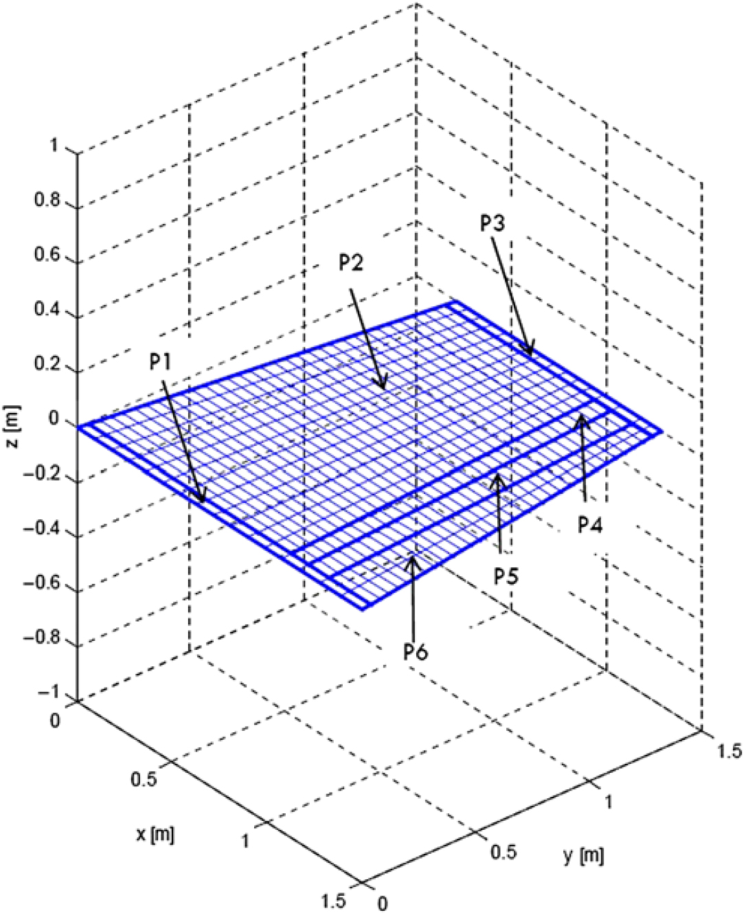
Figure 1. Aerodynamic grid for load computation.
Each panel has been subdivided in several lattice elements that have been reported in detail in the next Table 1, for both spanwise (y direction in Fig. 1) and chordwise (x direction in Fig. 1).
Table 1 VLM Panel Subdivision
For the specific aircraft category, reference operative speeds and wing structural configuration, no loss in aileron effectiveness is expected to occur; aeroelastic effects were consequently considered negligible for the evaluation of the aerodynamic loads and performances of the morphing device. Several cases have been evaluated for different wing angle of attack, rigid aileron deflection around the main hinge axis (namely ε) and angle γ between block B1 with respect to block B2 as shown in the next Fig. 2. The rotation γ is correspondent to the equivalent plain rotation considering the aileron a 1 DOF structure. It has been analysed 15 load cases for various combination of wing angle of attack and aileron deflection as stated in Table 2, showing that the most critical one (24) has been considered for structural sizing and it is widely greater than the maximum load expected in wind tunnel.
Table 2 Load cases considered for aileron structural sizing
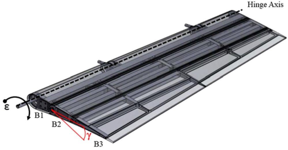
Figure 2. Representation of the Aileron Angles ϵ and γ.
3D flat-panel mesh was generated in correspondence to the outer wing segment. For each flight attitude and aileron shape, the lifting pressure (Pi) acting along each box (bi), was calculated according to the following equation:
 $$P_i = q_\infty {\rm{(}}P_{0,i} {\kern 1pt} + {\kern 1pt} \alpha P_{\alpha ,i} {\kern 1pt} + {\kern 1pt} \varepsilon P_{\varepsilon ,i} {\kern 1pt} + {\kern 1pt} \gamma P_{\gamma ,i} {\rm{)}}
$$(2)
$$P_i = q_\infty {\rm{(}}P_{0,i} {\kern 1pt} + {\kern 1pt} \alpha P_{\alpha ,i} {\kern 1pt} + {\kern 1pt} \varepsilon P_{\varepsilon ,i} {\kern 1pt} + {\kern 1pt} \gamma P_{\gamma ,i} {\rm{)}}
$$(2)where:
 $$
q = 0.5 \cdot \rho \cdot V_\infty ^2
$$
is the dynamic pressure, ρ the air density at the flight altitude and
$$
V_\infty ^2
$$
the airspeed
$$
q = 0.5 \cdot \rho \cdot V_\infty ^2
$$
is the dynamic pressure, ρ the air density at the flight altitude and
$$
V_\infty ^2
$$
the airspeedα is the wing angle-of-attack
P 0,i is the pressure arising on bi due only to unitary dynamic pressure at α and γ equal to zero (airfoil baseline camber effect)
P ε,i is the pressure on bi due only to the unitary ε at unitary dynamic pressure (pressure contribution due to aileron rigid rotation with respect to the wing)
P α,i is the pressure on bi due only to unitary α at unitary dynamic pressure (incidence effect)
P γ,i is the pressure on bi due only to unitary γ at unitary dynamic pressure (morphing effect)

Thanks to Equation (1), P 0,i, P α,i, P γ,i where calculated only one time for all the boxes and then combined according to the flight attitude parameters (α, q) and aileron morphed shape (γ) to be investigated under the hypothesis of linearity, i.e. small angles.The combination of α, q, γ leading to the most significant pressure level along aileron segments was then determined and used as design point for structural sizing purpose. The spanwise pressure distribution on the aileron segments at the design point (α = 2°, q = 4425N/m2, γ = 7°) are plotted in Fig. 3. This load has been considered as limit load for the design of the aileron structure and actuation system. Fig. 3 reports the pressure distribution along the span and along the three chordwise segments of the aileron. At each spanwise station, you have three values of pressure along the chord: the pressures at the centre of the aerodynamic boxes (Fig. 1) pertinent to the first, second and third segment of the aileron, moreover the pressure contour data on the upper and lower surfaces have been also reported with the resultant global forces.
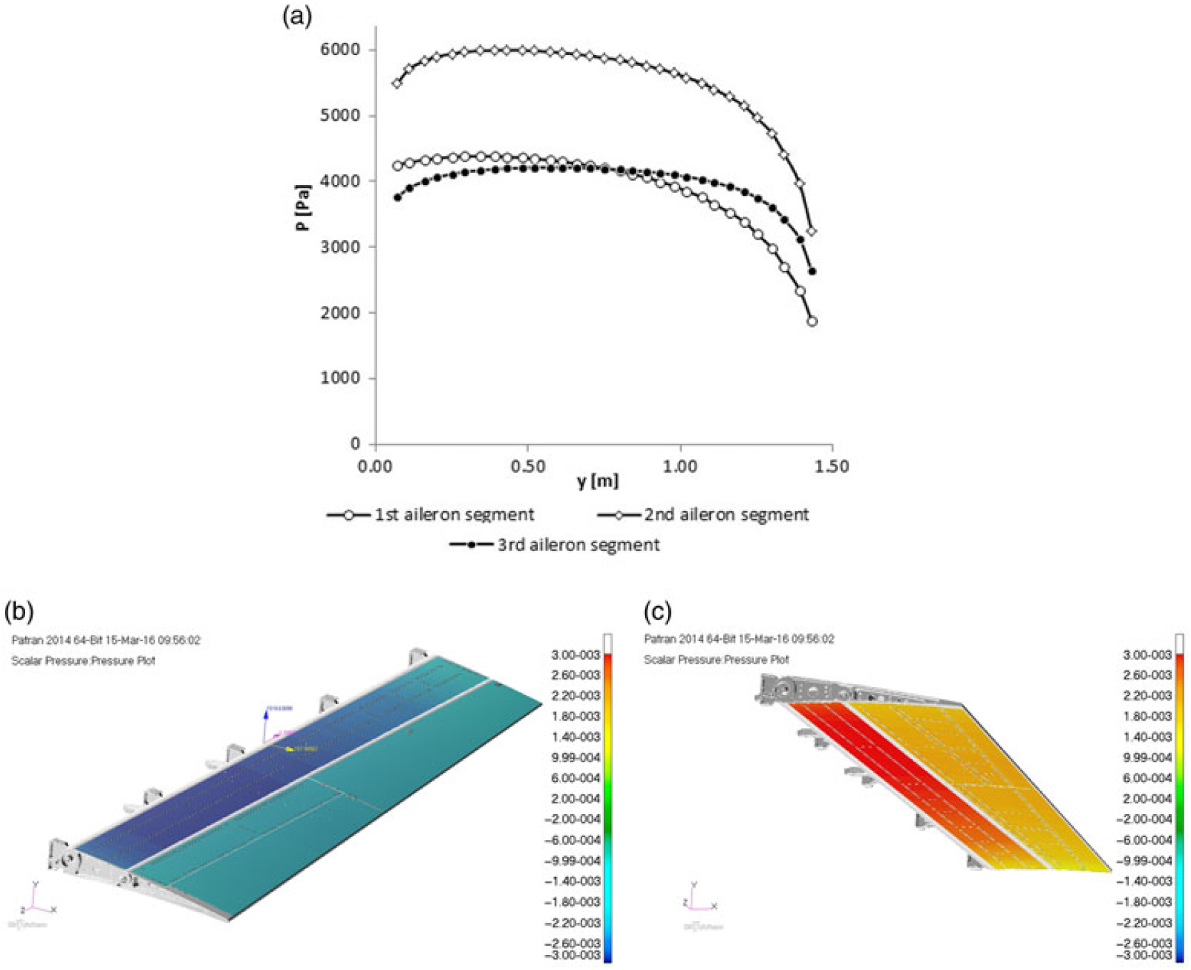
Figure 3. Pressure distribution along aileron span and chord (a) with contour on upper (b) and lower (c) surface. Pressure [MPa].
4.0 THE AILERON STRUCTURE
4.1 The morphing rib
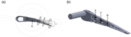
The morphing aileron consists of segmented adaptive ribs based on finger-like segments(Reference Pecora, Amoroso, Amendola and Concilio20) enabling aileron camber morphing upon actuation. Each rib (Fig. 4) is assumed to be segmented into three consecutive blocks (B1, B2, B3) connected to each other by means of two hinges located on the airfoil camber line (A,B). A three-blocks segmentation was considered sufficient in order to meet the desired target shapes. The morphed target shapes have been estimated by means of a 2D aerodynamic optimisation(Reference Botez, Koreanschi, Gabor, Mebarki, Mamou, Tondji, Guezguez, Tchatchueng Kammegne, Grigorie, Sandu, Amoroso, Pecora, Lecce, Amendola, Dimino and Concilio21) with the objective to increase Lift-Drag ratio. Block B1 is rigidly connected to the rest of the wing structure through a torsion tube enabling aileron rotation for roll control. Blocks B2 and B3 are free to rotate around the hinges on the camber line, thus physically turning the camber line into an articulated chain of consecutive segments. A linking rod elements (L) — hinged on not adjacent blocks — forces the camber line segments to rotate according to specific gear ratio.
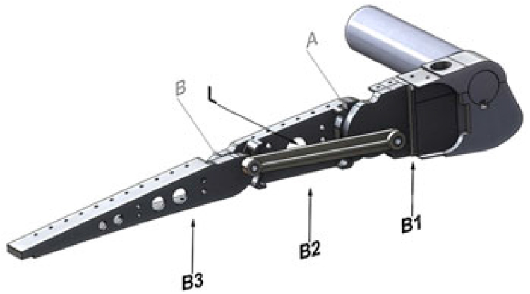
Figure 4. Morphing rib architecture: (a) blocks and links, (b) hinges.
An equivalent representation of the rib mechanism including only the position of the main hinge points is sketched in Fig. 5. In particular, the hinges A and B on the camber line, the hinges L1-1 and L1-2 representing the connection points between the link L and the rib blocks B2 and B3 respectively (see Fig. 4), are depicted. The morphed down configuration (dotted line) is also sketched together with the corresponding kinematic scheme (hinges’ positions in morphed down configuration have been marked with primes). The morphed down configuration was defined as the morphed shape characterised by the same tip displacement (TT’) induced by a rigid rotation of all the aileron around hinge A(Reference Amendola, Dimino, Magnifico and Pecora22).
Figure 5. Equivalent representation of the rib mechanism and aileron shapes in un-morphed and morphed patterns.
4.2 The structural skeleton
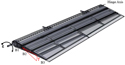
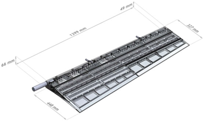
The ribs kinematic is transferred to the overall aileron structure by means of spanwise spars in a multi-box arrangement (Fig. 6). Each box of the structural arrangement is characterised by a single-cell configuration delimited along the span by homologue blocks of consecutive ribs, and along the chord by longitudinal stiffening elements (spars and/or stringers). Upon the actuation of the ribs, all the boxes are put in movement thus changing the external shape of the aileron; if the shape change of each rib is prevented by locking the actuation chain, the multi-box structure is elastically stable under the action of external aerodynamic loads. A four-bay (five-ribs) layout was considered for an overall (true-scale) span of 1.4 meters; AL2024-T351 alloy was used for spars, stringers and rib plates, while C50 steel was used for ribs’ links. Off-the-shelf airworthy components were properly selected for the bearing and bushings at the hinges and coupled to torsional springs to recover any potential free-play. A multi-module skin was considered in conformity to the multi-box segmentation; three aluminium-alloy panels were then adopted, each panel sliding over the consecutive one in an armadillo-like configuration. Airflow leakage at the skin segments interfaces was prevented through low-friction silicone seals. As one might expect, the segmented skin architecture does not significantly affect the aileron torsional stiffness and resulted slightly higher (but on the same order) of a conventional aileron.

Figure 6. Morphing aileron structure: multi-box arrangement.
4.3 The skin
For typical camber morphing application such as wing trailing edge or aileron, it is important to substitute the conventional skin (rigid and robust) with a flexible one which has to be deformable to allow the structural shape changing and at the same time robust to withstand aerodynamic pressure without yielding. Several design solutions can be found involving innovative materials such as polymeric foam or flexible matrix composites as described by(Reference Callister and Rethwisch23,Reference Murray, Gandhi and Vakis24) . It is important to mention the morphing skin developed inside Saristu Project. It was described by(Reference Schorsch, Lühring, Nagel, Pecora and Dimino25), and consist of a modular skin composed of flexible segments (foam) and stiff segments (aluminium parts). The entire skin is covered with an adhesive silicone layer to guarantee permanent connection and compactness among deformable foam and aluminium parts. It is evident that the skin design is truly dependent of the current application. This kind of choice, however, presents several drawbacks. The involved materials are not fully tested to the hard environmental conditions, typical of the aircraft operations, and it is expected that some more advance in the material development is necessary before they can safely be installed on-board. For this reason, an intermediate design between conventional and innovative materials was developed. In detail, a segmented skin was adopted, made of several contiguous blocks, sliding over each other. Each box was separately covered by a conventional metallic skin, properly riveted along spars and ribs plates generating an armadillo-like configuration. Rubber sealings were installed to preserve the continuity of the wet surface while covering the gap between the sliding skin panels; each sealing was bonded to only one panel. In this way, one edge resulted free to slide during morphing (Fig. 7), thus not penalising the actuation effort.
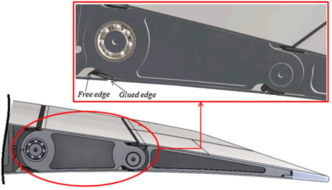
Figure 7. Sliding skin and rubber sealings (in black); detail of the sliding skin panels (upper box).
4.4 The kinematic system
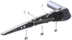
A commercial precision linear guide with recirculating ball carriages was considered (Fig. 8) in order to transmit the actuator torque through the actuation arm. The system is made of a light-weight and compact linear motion rolling guide comprising a U-shaped slip-table and a stainless steel track rail obtained by precision forming. The actuation architecture including the rotary actuator is shown in Fig. 9. The deployment kinematics use a ‘direct-drive’ actuation based on actuation arm that is rigidly connected to the B3 block of Fig. 4. This arm rotates the 1-DOF-based mechanical system and transmits the actuation torque from the actuator to the adaptive rib. The control actions aim at producing small camber variation in the adaptive aileron corresponding to a rigid rotation of a plain control surface comprised between –7° and +7° during flight.
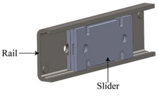
Figure 8. Precision linear guide with recirculating ball carriages(26).
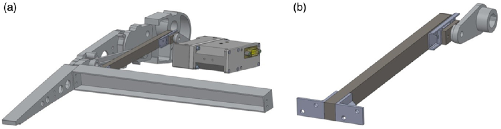
Figure 9. Actuation system using a precision linear guide mechanism.
5.0 ACTUATION SYSTEM
A light-weight and compact leverage was investigated to activate the morphing aileron through electromechanical actuators. An un-shafted distributed servo-electromechanical actuation arrangement is deployed to achieve the aileron shape transition from the baseline configuration to a set of design target shapes in operative conditions. The analytical scheme of the actuation system is based on slider-crank mechanism and its scheme is reported in Fig. 10. The rotational motion of the actuation beam is provided by the crank rotation β which moves the carriage along its guide. A force F is thus generated by the contact between the carriage and the rail. By connecting the actuator shaft to the crank hinge O and the beam to the third rib segment (B3), the actuation torque is transmitted firstly to the crank and secondly to the rib rotating around the hinge V in order to counterbalance the external moment Mrib#3.
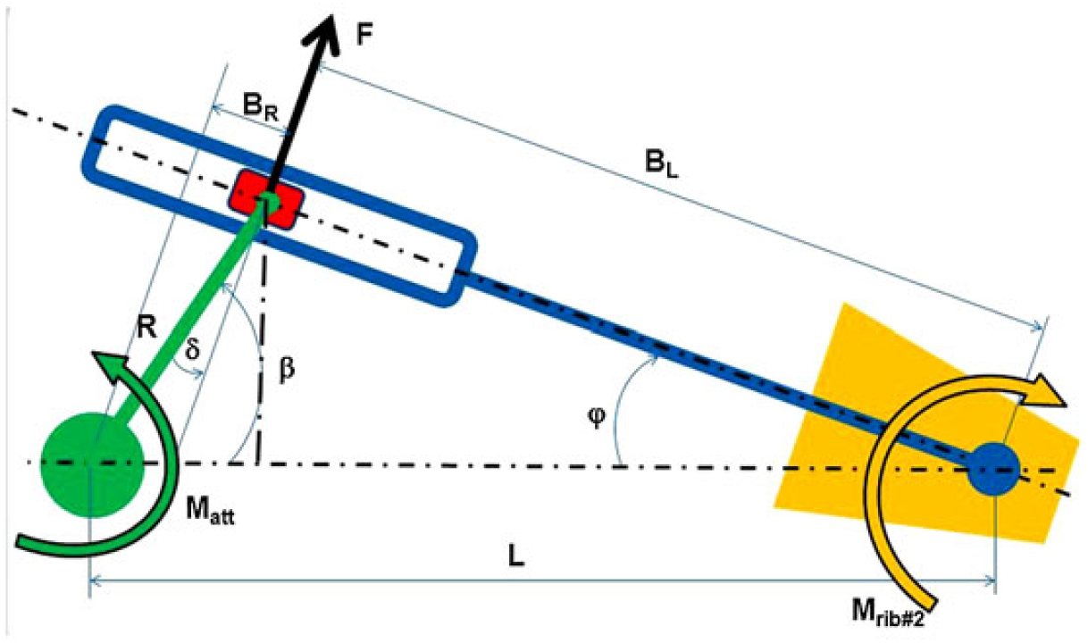
Figure 10. Oscillating glyph connected to the third rib segment of the morphing aileron.
The aileron shape can be, in this way, adaptively controlled to realise small camber variations. The mechanical advantage of the mechanism (indicated as MA) can be written as:
 $$
MA = {{LOAD} \over {DRIVER}} = {{M_{rib{\rm{\# }}3} } \over {M_{att} }} = {{FB_L } \over {FB_R }} = {{B_L } \over {B_R }}
$$
(3)
$$
MA = {{LOAD} \over {DRIVER}} = {{M_{rib{\rm{\# }}3} } \over {M_{att} }} = {{FB_L } \over {FB_R }} = {{B_L } \over {B_R }}
$$
(3)
where the Mrib#3 is the external moment due to aerodynamic loads estimated with respect to the hinge V, while Matt is the torque provided by the actuator in order to equilibrate the system. F is the force that the crank produces by means of the sliding cursor, BL is the force arm and BR is the crank projection along the guide movement direction. Equation (3) shows that the mechanical advantage only depends on the geometrical characteristics of the system, however, combining geometrical terms, it follows that Equation (3) can be written also as function of the angles ϕ and β. It is important to mention that the angle γ, indicated in Fig. 2 as the aileron morphing angle of the blocks 2 and 3 with respect to block 1, correspond to ϕ in the above Fig. 10. The expression of BL and BR can be derived:
 $$
B_R = R\;\sin \delta \;;\;B_L = L\;\cos \phi - B_R
$$
(4)
$$
B_R = R\;\sin \delta \;;\;B_L = L\;\cos \phi - B_R
$$
(4)
Substituting then Equation (4) into Equation (3), we obtain:
 $$
MA = {{B_L } \over {B_R }} = {{L{\kern 1pt} \cos \phi \;} \over {R{\kern 1pt} \sin \delta \;}} - {\rm{1}}
$$
(5)
$$
MA = {{B_L } \over {B_R }} = {{L{\kern 1pt} \cos \phi \;} \over {R{\kern 1pt} \sin \delta \;}} - {\rm{1}}
$$
(5)
Another important equation is Equation (8), which allows calculating the actuator shaft rotation (β) needed to achieve a given morphing angle (φ) of the rib block and hence of the entire mechanism. The Equation (8) can be easily obtained thanks to the following mathematical manipulations:
 $$
B_L \;\cos \phi {\kern 1pt} = {\kern 1pt} L - R\;\cos \beta \;
$$
(6)
$$
B_L \;\cos \phi {\kern 1pt} = {\kern 1pt} L - R\;\cos \beta \;
$$
(6)
 $$
B_L \;\sin \phi \; = R\;\sin \beta \;
$$
(7)
$$
B_L \;\sin \phi \; = R\;\sin \beta \;
$$
(7)
The ratio between the above equations gives:
 $$
\cot \phi = {L \over {R\;\sin \beta \;}} - \cot \beta \;
$$
(8)
$$
\cot \phi = {L \over {R\;\sin \beta \;}} - \cot \beta \;
$$
(8)
After estimating MA, it is possible to calculate the actuation torque that the electrical actuator has to supply. Accordingly, the force F should be known in order to verify that the stress arising in the rail carriage does not exceed design allowable levels. The actuation rod is then subjected to the simultaneous action of F and Mrib#3 , both producing bending stress. This indicates that the actuation system design requires a trade-off between the mechanical advantage and the geometrical limits for the actuator shaft rotation and the ratio L/R. The deployment kinematics is based on a direct-drive actuation, moving a beam rigidly connected to the block B3, Fig. 4. The actuation beam transmits the actuation torque to the third rib segment, which then rotates with respect to its original position in a specific plane. All the points rotates around an instantaneous center (IC) of rotation (named V) at a certain time instant. As illustrated in Fig. 11 (a), each point of the third block moves along circles, centered in V. The determination of its coordinates allows estimating the actuation torque, needed to withstand the aerodynamic loads acting on the morphing rib structure.
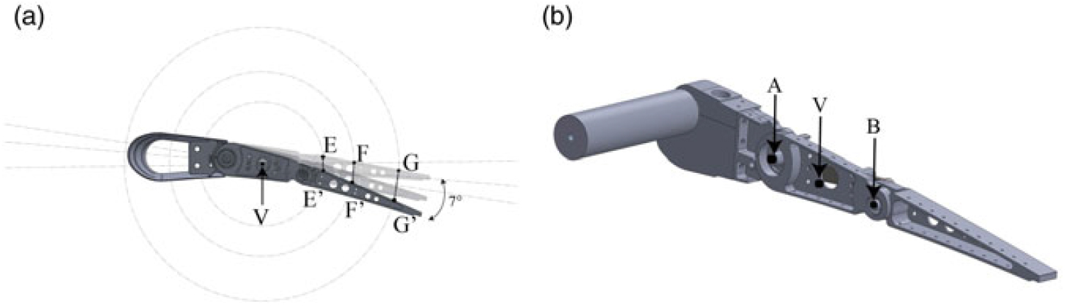
Figure 11. Circular trajectories of sample points (E, F, G) during morphing (a) and hinges position A, V and B (b).
According to such considerations, MA was calculated for different positions of the virtual hinge V. When the rib is morphing down or up, V moves farther or closer to the crank position O, respectively, thus changing the length BL that is directly linked to the MA by Equation (5). It is important to show the graphical trend of the mathematical relation of the MA for different geometrical configurations (distance OV). Several curves are plotted in Fig. 12, where it is noticeable that when the ratio L/R augment (increase the distance of the point V from O), the MA curve (Equation (5)) translates upward toward greater value because the mechanism exhibits a more efficient leverage.
Figure 12. Mechanical Advantage curves with different geometric configurations.
Moreover, the Fig. 13 shows the torque trend with the morphing angle (φ), and it is meaningful to notice that Figs. 12, 13 are interconnected. The torque has been estimated dividing the external moment Mrib#3 by MA in such a manner, the highest curves in Fig. 13, obtained for L/R = 3.3, corresponds to the lowest curve of the MA. There are two contributions to the actuator torque: the external load (maximum in morphed down) and the mechanical advantage. When the aileron is positioned at 0° degree of deflection, the actuator torque is maximum notwithstanding the lower external moment because in this configuration the mechanical advantage reaches its minimum value. Therefore, when the external load increases, the MA increases more than the applied loads resulting in a lower actuator torque. For this reason, in the following Fig. 13, it is visible that at 0 degree the torque become maximum. At this point, for structural sizing, the aerodynamic limit load of paragraph 3 has been applied to the structures at the un-morphed configuration (0 deg) correspondent to the minimum value of the MA (maximum torque).
Figure 13. Curves of the actuator torque for several geometric configurations.
In order to preliminarily validate the analytic model, a multi-body simulation, describing the glyph mechanism, has been carried out and the main results are reported in Fig. 14.
Figure 14. Comparison among linear, analytic and multi-body simulation of the Equation (2).
The diagram shows a good correlation between the results provided by the model described by Equation (8) and the numerical simulations. For small actuator rotations, the functional relationship is practically linear. However, at high values of β, this assumption cannot be hold because it is conspicuous a large deviation from the linear trend.
6.0 NUMERICAL MODELING AND RESULTS ANALYSIS
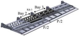
Pressure distribution calculated by means of vortex lattice method (paragraph 3), was approximated by equivalent lumped loads applied to each aileron rib, according to the scheme shown in Fig. 15 concerning Rib 3 between Bay 2 and 3. In this phase we are interested to compute, for the most loaded rib (Rib number 3), the moment with respect to the instantaneous centre V imposing a constraint to that point. A detailed FE model of the morphing rib was carried out, as reported in Fig. 16 where the rib has been modelled by TET10 elements. Block B1 was considered fixed, and the out-of-plane displacements of B2 and B3 were constrained. The rib block B3 was connected to V through rigid MPC of the RBE2 typology(27).

Figure 15. Sketch of the concentrated loads evaluation (hidden skin).
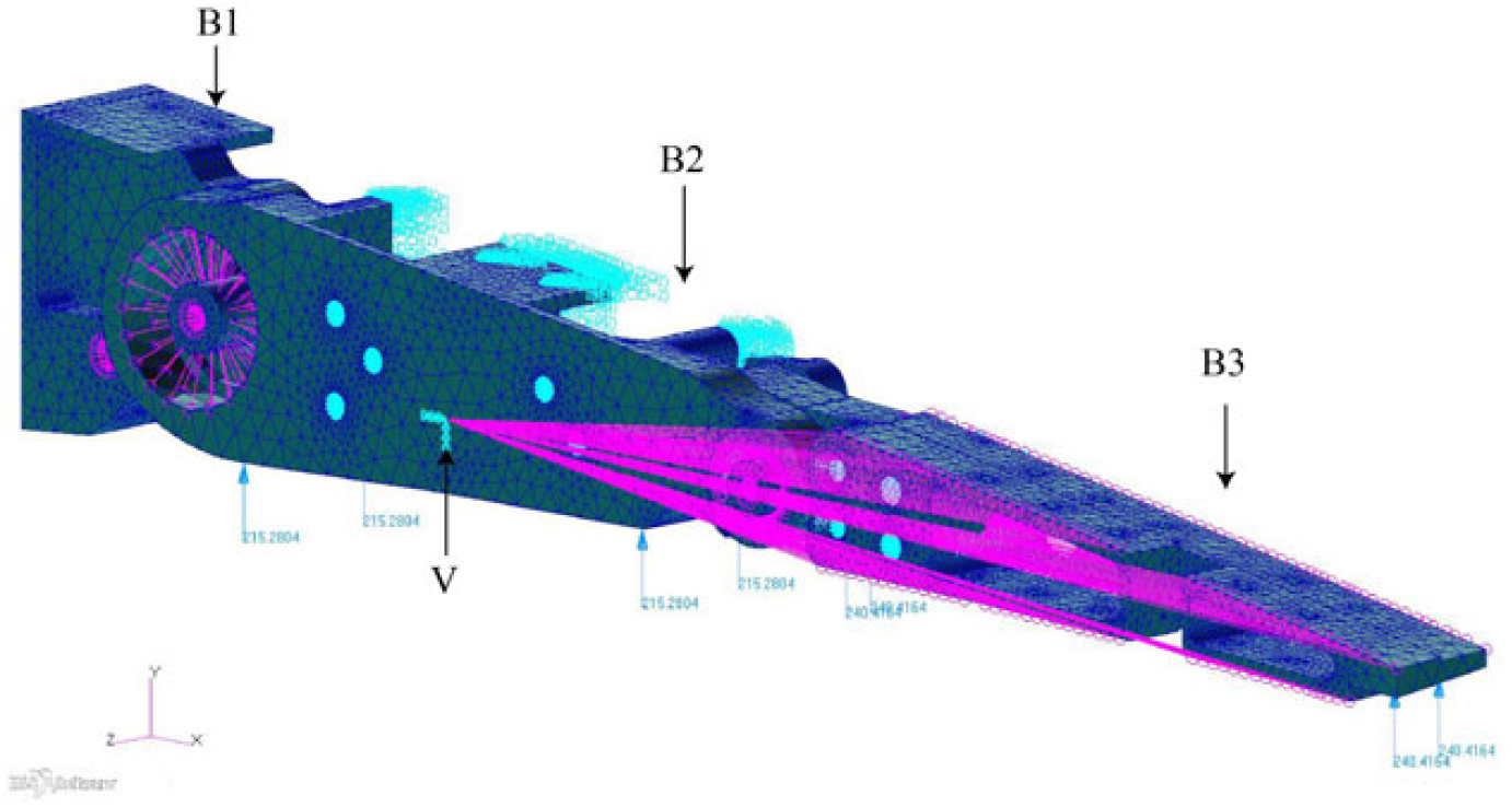
Figure 16. Complete FE model of the aileron rib.
A static analysis was carried out to calculate the operational moment Mrib#3 resulting from the limit load. The aerodynamic moment applied to the rib (indicated as Mrib#3 ) has been divided by the MA in order to predict the actuator torque needed to withstand the operative loads. The main results are recapped in the Table 3.
Table 3 Actuator torque values

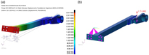
The results indicates that a rotary actuator must provide a torque equal to ~ 4 Nm in order to equilibrate the rib under the external loads. The next step consist of a detailed analysis on the actuation system including the precision linear guide with recirculating ball carriages, the crank and the actuation beam. It is important to mention that the kinematic chain has been integrated into the rib geometry, as previously shown in Fig. 9, so that the geometrical parameters (L/R, BR and BL ) are fixed to the design value and for this reason the MA and Torque curves are uniquely defined. The value of L/R is equal to 4 for the kinematic examined. The items of the kinematic chain were then modelled by means of finite elements using TET10 elements and only the results representative of the worst condition are reported (0 deg of morphing). A linear static analysis was, in a first approximation, performed. The aim of the numerical simulation was to verify if the vertical static force acting on the linear guide was below the allowable value prescribed by the producer. In the real operative condition, the linear guide is free to slide along its rail by means of the actuator shaft rotation transmitted by the crank. Being free to move, the guide is not subjected to stress in the direction of motion. Force are transmitted in the vertical (with respect to the guide axis) and, partially, normal direction (with respect to the guide plane). This is its regular way of working. For the current application, the actuator system was sized, referring to the jamming condition, considered as the most critical. In fact, the larger extent of the constraints (additional clamps) is expected to lead to higher stresses, locally (in the contact region) and distributed (overall). When the linear guide is blocked in fact, the actuation beam is simultaneously loaded with the external aerodynamic moment (respect to V), the vertical static force acting on the slider and a horizontal component (linked to the jamming), both producing a pure bending state with a higher stress level rather than the free guide. These considerations are validated by the study conducted by(Reference Dimino, Flauto, Diodati, Concilio and Pecora14) where a non-linear simulation was conducted, showing a low level of structural stress. The hypothesis of a perfect bonding between the rail and slider was formulated and implemented; in such manner, the analyses was then conducted. The kinematic analysis is aimed to estimate the stress and the force acting on the linear guide item. A conservative approach has been assumed where the baseline (un-morphed) structure, whose actuation chain exhibits the lowest mechanical advantage, was loaded by the highest aerodynamic moment (33.81 Nm) associated with the morphed configuration (+7 deg). FEA results are reported in Fig. 17, in terms of total displacements (maximum value: 3.01 mm at beam tip) and load transmitted to the guide (maximum value 371 N).

Figure 17. Beam displacement contour (a); guide reaction loads of 371 N (b) at 0° of morphing.
Furthermore, the stress acting on the linear guide are depicted in Fig. 18. It is reported the Von Mises magnitude stress on the left and its component along x direction on the right image. It is noticeable the high stress level in the direction of motion that will become null when the guide slides.
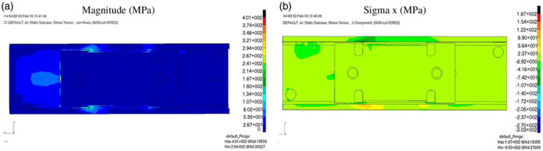
Figure 18. Stress contour on linear guide (slider plus rail), Von Mises a) and X component b).
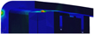
Moreover, as expected, high local stress in the contact region was found (Fig. 19).

Figure 19. Stress peak in the contact region between slider and rail.
In Fig. 20, it has been reported a comparison between analytical model (Equation 4) and finite element results for the mechanical advantage versus Morphing Angle (ϕ) and finally for the actuator torque during the rib deflection. The graphs in Fig. 20 are estimated for the design value of the distance OV. An excellent agreement between the two curves was achieved.

Figure 20. Comparison between analytical and numerical trend of Actuation torque and Mechanical Advantage versus Morphing Angle (ϕ).
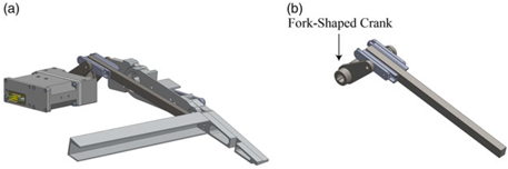
As results of the previous FEM, the maximum static force acting on the linear guide is 371 N. However, being the maximum allowable static force that can be applied to the linear guide limited to 140 N (prescribed by the producers(26), it was then demonstrated that single-sided linear guide solution was structurally inadequate. Other designs have been addressed also by(Reference Amendola, Dimino, Magnifico and Pecora22). As a result, an alternative linear guide-based device based on a non-recirculating ball carriage was investigated, as shown in Fig. 21. This device exhibits substantial benefits, mostly resulting in an increased allowable static force equal to 232N. In addition, in order to mitigate the maximum counterbalancing load acting on the guide to equilibrate the aerodynamic moment, a fork-shaped crank coupled with a double-sided linear guide was also preferred, as shown in Fig. 22. Nevertheless, such a solution resulted in a lower mechanical advantage for the given morphing angle due to the slightly lower BL.
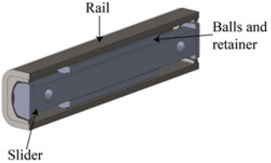
Figure 21. Precision linear slide with non-recirculating ball carriages.

Figure 22. Double sided linear guides-based actuation system driven by a fork-shaped crank.
Figure 23 shows the actuation forces needed to withstand the aerodynamic load arising in the morphed configuration (+7 deg). Moving from a single to a twin guide, it is verified that the MA as a function of the morphing angle, assumes lower values. As a consequence, actuator torque reduces slower than before. Because the effective arm (BR ) reduces as the morphing angle increase, the actual forces on the crank hinges grow as a function of that rotation. Therefore, the most severe condition in terms of vertical force results the one at max deflection (7 deg). Results are summarised in Table 4. It is clearly noticeable that although in baseline (un-morphed) condition, the actuation chain is subjected to lower pressure loadings, the actuation system shall provide higher torque in order to balance the external aerodynamic moment. Compared to the single guide-based actuation system, the designed architecture reaches a mechanical advantage of just 4.20 at +7 deg.
Table 4 Comparison between analytical and numerical results for the linear guide-based actuation system

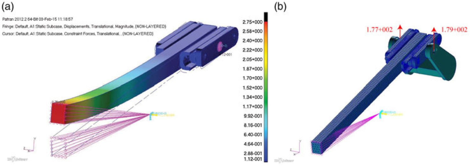
Figure 23. Actuation beam displacement contour (a); guide reaction loads of 177 N and 179 N respectively (b).
7.0 CONCLUSIONS
In this paper, an actuation system designed for a smoothly and no gaps chord wise camber variation of a morphing aileron has been presented. The actuation mechanism is based on an oscillating glyph mechanism, combining the characteristics of functionality, robustness and integrability demanded to adaptive structures. The study of the mechanical system involved the functional integration of the actuation chain into the finger-like adaptive ribs architecture. Aerodynamic pressure distributions evaluated through VLM were reduced to an equivalent set of lumped forces in order to conveniently simulate the loads acting on the actuation mechanism. Aeroelastic studies will be addressed to measure the impact of structural elasticity on morphing device aerodynamic performances; aeroelastic stability analyses will be also carried out to prove that the device has no influence on aircraft clearance from flutter and control reversal. The study started from the analytical description of the actuation kinematics in order to predict actuation torque and actuators shaft rotation. A conceptual architecture based on a linear guide with recirculating balls carriage has been numerically assessed; however, on the basis of the first design loop results, a more compact solution with double-sided guides and a fork-shaped crank has been investigated. This architecture shows potential for its capability to split the total vertical load acting on the single guide system into two forces, leading to internal stresses lower than the allowable of the linear guides material. Furthermore, thanks to the fork-shaped crank, actuation beam torsion is also avoided with respect to the first single-guide system.
ACKNOWLEDGEMENTS
The authors wish to acknowledge ETS (L’École de Technologie Supérieure), NRC (Canadian National Research Council), Bombardier Aerospace, Thales Aerospace and Alenia Aermacchi for their technical support as partners of the CRIAQ MDO-505 project. Special acknowledgements go to Prof. Ruxandra Mihaela Botez (ETS), coordinator of CRIAQ MDO-505 project, for having defined suitable framework and targets for the research addressed by this paper.