


NOMENCLATURE
- CCE
Composite Cycle Engine
- HEX
Heat Exchanger
- HPC
High-Pressure Compressor
- HPT
High-Pressure Turbine
- IC
Intercooler
- IPC
Intermediate Pressure Compressor
- IR
Intercooled Recuperation
- LPT
Low-Pressure Turbine
- PC
Piston Compressor
- PE
Piston Engine
- PPS
Power Plant System
- REC
Recuperator
- A
heat exchanger area; m2
- BPR
Bypass Ratio
- C
heat capacity rate; W/K
- cp
specific heat capacity; J/kg/K
- FB
Fuel Burn
- FHV
Fuel Heating Value; MJ/kg
- k
heat transfer coefficient; W/m2/K
- m
mass; kg
- M
Mach number
- NTU
Number of Transfer Units
- OPR
Overall Pressure Ratio = p35/p2
- p
total pressure; Pa
- T
total temperature; K
- TSFC
Thrust Specific Fuel Consumption; g/kN/s
- v
velocity; m/s
- w
mass flow rate; kg/s
- ε
ηeat exchanger effectiveness
- η
efficiency
- 0
free-stream
- 1–5
engine stations (see Fig. 8)
- c
compressor
- cold
heat exchanger cold side
- cool
cooling flow
- ex
heat exchanger exit
- in
heat exchanger inlet
- hot
heat exchanger hot side
- mat
heat exchanger matrix
- p
polytropic
- plumb
heat exchanger plumbing
- rel
relative
- t
turbine
Symbols
Subscripts
1.0 INTRODUCTION
Radical engine concepts are being investigated to improve engine efficiency beyond the limits of the Joule-/Brayton-cycle based turbofan engine to aim to achieve ACARE 2050 emission reduction targets(1,2) . These suggest a reduction of CO2 emissions per passenger kilometre by 68% compared to year 2000 technology standards coming from reduced energy demand by propulsion system and aircraft(2). Assuming an equal contribution by both, the propulsion system would need to contribute a reduction of emissions by 43%. Alternatively, a part of the energy demand may be retrieved through installation effects reducing the required power to generate a given amount of thrust, such as boundary-layer ingestion(Reference Bijewitz, Seitz, Isikveren and Hornung3). This may reduce the emissions by 7%, still requiring further 40% reduction by propulsion system and aircraft(Reference Grönstedt, Xisto, Schmitz, Donnerhack, Lundbladh, Yakinthos, Seitz, Sethi, Rolt, Newton, Tantot and Garcia Rosa4). From today's perspective, it appears highly unlikely that such radical improvements can be achieved with the conventional Joule-/Brayton cycle(Reference Kaiser, Seitz, Vratny and Hornung5). Under realistic assumptions, even the target of achieving a 30% emission reduction by a turbofan architecture appears to be very challenging(Reference Kaiser, Seitz, Vratny and Hornung5). For example, for a large turbofan with entry into service year 2025, an improvement of 23.4% was forecasted(Reference Von der Bank, Donnerhack, Sturm, Flouros, Bruna, Stokes, Poutriquet, Bourgois, Obrecht, Tantot, Lundbladh, Wallin, Forsman, Avellan, Antoranz, Caballero, Torre, Morales, Ornat, Mrugala, Kraj, Peschiulli, Turrini, Colantuoni, Basset, Palat, Ruzicka, Johann, Seitz, Gebel and Dörr6), and the Rolls-Royce UltraFan™ has a projected efficiency improvement of 25% with year 2025+technology readiness(Reference Haselbach, Newby and Parker7). Therefore, the investigation of novel architectures is warranted.
One promising candidate concept is the Composite Cycle Engine (CCE) that allows fuel burn improvements of 15–20% compared to a Joule-/Brayton-based turbofan of similar technology level. The CCE uses a highly charged piston-based gas generator in the core engine, pressurised by turbo compressors and turbines for power extraction. In this way, the CCE combines high efficiency and high peak temperature capability of piston engines and the high power density of turbomachinery. An example conceptual arrangement is depicted in Fig. 1 with a piston system placed between the combustor/turbine section of the core engine and the bypass duct. The piston system is charged by an intermediate pressure compressor and pre-cooled by an intercooler located directly upstream of the piston system. The piston system is mechanically decoupled from the turbo shafts to allow rotation at an independent speed and to dispense with the necessity for a gearing system.
Figure 1. Conceptual drawing of a CCE with intercooler (adapted from Ref. 9).
Design considerations, engine configuration and off-design behaviour are discussed in Reference Kaiser, Donnerhack, Lundbladh and SeitzRef. 8. It applied the concept to a regional aircraft platform with a regional turbofan of year 2025 technology standard with a crankshaft connected piston system, and it showed a fuel burn advantage of 15.2% for the CCE. Further studies showed a consistent advantage of about 18% for both state-of-the-art technology and year 2035 technology standard(Reference Kaiser, Seitz, Vratny and Hornung5). Challenges associated with the concept are engine weight increase of 17–32%, mainly driven by the piston components, and demanding operating conditions for the piston components at high temperatures and pressures.
Another promising concept is Intercooled Recuperation (IR) in aero engines exploiting exhaust gas waste heat by utilising it to preheat the intercooled compressor discharge air before it enters the combustion chamber resulting in reduction of fuel consumption and pollutant emissions. This concept is based on the integration and use of a number of heat exchangers, comprising a recuperator system, carefully mounted inside the hot gas exhaust nozzle, in order to avoid induced pressure losses, and an intercooler mounted between the compressor stages, so as to reduce the required compressor work. This concept has been mostly developed by MTU Aero Engines AG and investigated in large European funded research projects such as: CLEAN (Component vaLidator for Environmental-friendly Aero-eNgine), AEROHEX (Advanced Exhaust Gas Recuperator Technology for Aero-Engine Applications), NEWAC (NEW Aero engine Core concepts), and LEMCOTEC (Low Emissions Core-Engine Technologies)(Reference Goulas, Donnerhack, Flouros, Misirlis, Vlahostergios and Yakinthos10–Reference Boggia and Rüd12).
The intercooled recuperative engine concept is schematically shown in Figs 2 and 3 together with the MTU developed state-of-the-art tubular Heat Exchanger (HEX) of elliptic tube profile.

Figure 2. The IR turbofan engine concept, developed by MTU Aero Engines(Reference Goulas, Donnerhack, Flouros, Misirlis, Vlahostergios and Yakinthos10).

Figure 3. The heat exchanger consisting of the recuperator's installation(Reference Goulas, Donnerhack, Flouros, Misirlis, Vlahostergios and Yakinthos10).
In this paper, architectures for synergistic combinations of CCE and IR are explored and analysed through a conceptual analysis approach. The target of the studies is to identify thermodynamically feasible and beneficial generic configurations. At first sight, the introduction of heat exchanger addresses the challenges of the CCE and further improves fuel utilisation. This may be achieved by Intercoolers (ICs) reducing the piston system's thermal load and weight, and/or Recuperators (RECs) utilising waste heat to improving efficiency.
An IC may be introduced either between Intermediate Pressure Compressor (IPC) and Piston Compressor (PC), or between PC and Piston Engine (PE), as presented in Fig. 4. The first option in Fig. 4(b) aims to reduce power required for compression in the PC and to reduce piston system size by increasing fluid density. The second option in Fig. 4(c) allows to cool the air in front of the PE considerably in order to reduce thermal loads downstream the IC. This dispenses with power and weight saving in the PC and has a large penalty in thermal efficiency, because heat is removed at high pressure.

Figure 4. Schematic drawings of (a) the baseline and (b), (c) intercooler installation options with station nomenclature.
To recover waste heat for the purpose of reducing fuel consumption, several options are conceivable, as displayed in Fig. 5. First, a heat exchanger may be employed as a classical REC after the LPT to transfer heat from the exhaust flow to the main flow after the piston system and before the combustor (Fig. 5(a)), reducing fuel required. Second, the cooling air flow extracted after the PC may be preheated before being used in the HPT as proposed by(Reference Klingels9) (Fig. 5(b)). The cooling air has a lower temperature than the piston engine exhaust temperature at given cycle parameters. Furthermore, it operates on a small mass flow and reduces thermal gradients in the cooled HPT blades. On the flip side, cooling air mass flow ratio increases since the cooling air is preheated. Third, the REC may be supplied with air which bypasses the piston engine and is mixed with piston engine air before the combustor (Fig. 5(c)). Here, the air also has a low temperature after the PC. The air used for recuperation is not available for the PE in addition to the cooling bleed mass flow. Adding heat before the PE appears promising thermodynamically because the topping cycle would operate at even higher temperature levels. This option has been rejected because piston engine size would increase, and the material constraints are already very challenging due to high temperatures in the piston cycle. Breakthrough material solutions for piston engines would warrant a revisitation of this kind of cycle, however.

Figure 5. Schematic drawings of heat exchanger application options: (a) Recuperator, (b) Bleed Pre-Heater, and (c) Bypass Recuperator with station nomenclature.
The temperature levels in a typical CCE cycle make achievement of recuperation after the LPT difficult, especially when the cycle parameters are optimised for optimal PE operation and when no additional modifications for the CCE are made. For example, the piston engine exhaust temperature T 35 of the CCE baseline cycle used in this paper is 1190 K at top of climb, while the LPT exit temperature T 5 is only 700 K as displayed in Fig. 6. The resulting temperature difference is 490 K in the wrong direction, meaning recuperation is not feasible under these conditions.
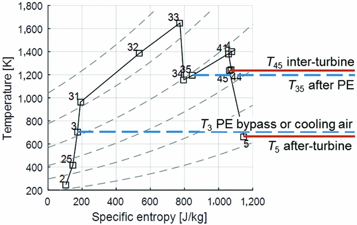
Figure 6. Temperature over entropy diagram for the CCE baseline cycle with T 4 = 1400 K and OPR = 33. For useful heat exchange, the red solid line must be over the blue dashed line.
As a result, the CCE, IC and REC concepts have the potential to operate synergistically if other conditions are chosen that imply a different power balance not specifically optimised for a CCE concept without IR, and provide an overall optimised cycle performance. Therefore, two additional modifications for improved waste heat management exploitation are investigated. First, sequential combustion may be employed between HPT and LPT to raise the exhaust temperature level (Fig. 7(b)). The heat in the second combustor is added at low pressure, thus having a lower work potential. Second, the REC may be relocated between the HPT and the LPT (inter-turbine recuperation, Fig. 7(b)). This location clearly improves the temperature conditions for recuperation, but heat is extracted before the LPT, thus reducing the work potential. In both cases, the drawbacks would need to be over-compensated by recuperation.

Figure 7. Schematic drawings of heat exchanger installation location options: (a) after-turbine, (b) sequential combustion and (c) inter-turbine with station nomenclature.
To examine the applicability of the heat exchanger options and combinations of them, they were benchmarked in parametric studies varying Overall Pressure Ratio (OPR) and combustor exit temperature T 4 and were assessed on a conceptual level. The ranges were chosen to also account for cycles with high T 4 and low OPR, which may enable temperature conditions allowing for recuperation. The modelling approach is introduced in the next section. From the parametric studies, the useful and feasible architectures combining CCE and IR were deducted in the ‘Results’ section. There, the concepts were evaluated using Thrust Specific Fuel Consumption (TSFC), engine weight and Fuel Burn (FB).
2.0 METHODS
The power plants are modelled in a simple and robust manner in order to allow quick implementation of novel architectures and validity of the results in a large range of parameters. The base architectures are set up as depicted in Fig. 8 combining inner fan, IPC and HPC into one unit, driven by the HPT. This simplifies calculation procedures and the definition of figures of merit, particularly core efficiency according to Ref. 13. Thermodynamics are represented with half-ideal gas properties and chemical equilibrium combustion characteristics. The piston system is represented as a Seiliger cycle with adapted performance parameters. The detailed modelling is extensively described in Reference Kaiser, Seitz, Vratny and HornungRef. 5. The method set represents the most important design parameters by incorporating compressor sizing effects, cooling air demand and preliminarily component weights. The weight of the turbo components and piston components is estimated based on simple geometric representations, and were calibrated to state-of-the-art turbofan engines.
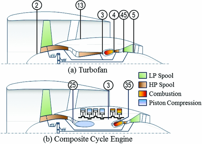
Figure 8. Power plant schematics with station nomenclature (adapted from Ref. 5). (a) Turbofan. (b) Composite Cycle Engine.
The component efficiencies were adapted to reflect an improvement for the turbofan engine of 25% for year 2050 compared to year 2000 technology level. The assumptions are summarised in Table 1. It may be highlighted that turbo component efficiencies additionally include mechanical shaft, bearing and power gear box losses as well as customer power off takes. The denoted combustion chamber pressure loss comprises losses in the combustion chamber itself, turbo compressor and turbine duct, and the core nozzle. For sequential combustion chamber, half of that loss, i.e. 3.75%, is assumed since it only represents the combustion chamber loss itself. The bypass pressure drop additionally includes stream tube, intake and bypass nozzle losses. Mechanical losses in the piston system account for 4% of the work obtained during the PE expansion stroke, which corresponds to about 7.5% of the net output shaft power, or a friction mean effective pressure of 70 kPa under top of climb conditions.
Table 1 Assumed technology standard for a year 2050 engine

The engines are compared for an application to an inter-continental wide-body aircraft (design range 7,000 nm; 300 passengers; cruise Mach number 0.80). A preliminary sizing thrust of 59.4 kN was assumed with a fan diameter of 3.50 m. The aerodynamic sizing point is at top of climb (35,000 ft; ISA; M0.8).
The parametric studies allow to conclude TSFC, basic geometric engine dimensions (such as fan diameter), and a simplified estimation of component weights. The impact on aircraft level in contrast to the reference turbofan can then be deducted with trade factors. These allow calculating the change in fuel burn due to changes in TSFC and power plant system mass m PPS including cascading effects due to changed aircraft weight and resizing of the aircraft structures. The trade factors are
 $$\begin{equation}
{\rm{\Delta F}}{{\rm{B}}_{{\rm{TSFC}}}} = 1.44 \cdot {\rm{\Delta TSFC}}
\end{equation}$$\\
$$\begin{equation}
{\rm{\Delta F}}{{\rm{B}}_{{\rm{TSFC}}}} = 1.44 \cdot {\rm{\Delta TSFC}}
\end{equation}$$\\
 $$\begin{equation}
{\rm{\Delta F}}{{\rm{B}}_m} = 0.00238\frac{\% }{{{\rm{kg}}}} \cdot {\rm{\Delta }}m
\end{equation}$$
$$\begin{equation}
{\rm{\Delta F}}{{\rm{B}}_m} = 0.00238\frac{\% }{{{\rm{kg}}}} \cdot {\rm{\Delta }}m
\end{equation}$$
A heat exchanger model has been added to simulate ICs and RECs, and adequately represent pressure drop and weight of heat exchanger matrix and plumbing. The models scale the heat exchanger according to heat exchanger effectiveness ε by means of Number of Transfer Units (NTU)
 $$\begin{equation}
{\rm{NTU}} = \frac{{k \cdot A}}{{{\rm{min}}\left( {{C_{{\rm{hot}}}},{C_{{\rm{cold}}}}} \right)}}
\end{equation}$$
$$\begin{equation}
{\rm{NTU}} = \frac{{k \cdot A}}{{{\rm{min}}\left( {{C_{{\rm{hot}}}},{C_{{\rm{cold}}}}} \right)}}
\end{equation}$$
with the heat transfer coefficient k, the heat exchange area A, and the minimum of the hot side and the cold side heat capacity rate C hot and C cold. The heat capacity rate C depends on the specific heat capacity cp and the mass flow rate w
 \begin{equation}
C = {c_p} \cdot w
\end{equation}
\begin{equation}
C = {c_p} \cdot w
\end{equation}
It is assumed that the ratio of heat capacities C hot/C cold is one. The heat exchanger effectiveness ε is defined as
 $$\begin{equation}
{\rm{\varepsilon }} = \frac{{{T_{{\rm{cold}},{\rm{ex}}}} - {T_{{\rm{cold}},{\rm{in}}}}}}{{{T_{{\rm{hot}},{\rm{in}}}} - {T_{{\rm{cold}},{\rm{in}}}}}},
\end{equation}$$
$$\begin{equation}
{\rm{\varepsilon }} = \frac{{{T_{{\rm{cold}},{\rm{ex}}}} - {T_{{\rm{cold}},{\rm{in}}}}}}{{{T_{{\rm{hot}},{\rm{in}}}} - {T_{{\rm{cold}},{\rm{in}}}}}},
\end{equation}$$
with the cold side inlet and outlet temperatures T cold,in and T cold,ex as well as the hot side inlet temperature T hot,in. The NTU for a cross-flow heat exchanger can then be related with ε according to Ref. 16 with the following fit valid between ε = 0.3–0.8:
 $$\begin{equation}
{\rm{NTU}} = \frac{{0.9 \cdot {\rm{\varepsilon }}}}{{0.882 - {\rm{\varepsilon }}}}
\end{equation}$$
$$\begin{equation}
{\rm{NTU}} = \frac{{0.9 \cdot {\rm{\varepsilon }}}}{{0.882 - {\rm{\varepsilon }}}}
\end{equation}$$
Choosing a heat capacity ratio C hot/C cold other than one results in a higher heat exchanger effectiveness ε for a given NTU, but overall losses increase(Reference Hesselgreaves17). It may still be considered to achieve a more compact HEX or lower losses of one side on the HEX.
This approach including Equation (6) presents a simplification to describe IC and REC behaviour for conceptual investigation. More dedicated and refined correlations that take variations of the heat capacity ratios into consideration must be adopted in order to quantify the IC and REC beneficial contribution more accurately to the overall thermodynamic cycle. As can be seen from Equation (3), heat exchanger area A and heat transfer coefficient k can be traded for a given NTU. With the target of a compact and lightweight design for aero engines, i.e. small A, the heat transfer k needs to be large. High heat transfer usually required high pressure drop across the heat exchanger Δp. Based on the above assumption, which will be further refined in future work, and assuming a constant heat transfer coefficient k and specific heat capacity cp of the flow, the heat exchanger area A is proportional to NTU and mass flow rate w. The matrix weight m mat is assumed to be proportional to A. Calibrating the values for IC and REC to values given for ε = 0.75 in Reference GriebRef. 16, the following matrix weights dependent on ε and w were derived:
 $$\begin{equation}
{m_{{\rm{mat}},{\rm{IC}}}} = 3.2 \cdot {w_{{\rm{IC}}}} \cdot \frac{{\rm{\varepsilon }}}{{0.882 - {\rm{\varepsilon }}}}
\end{equation}$$\\
$$\begin{equation}
{m_{{\rm{mat}},{\rm{IC}}}} = 3.2 \cdot {w_{{\rm{IC}}}} \cdot \frac{{\rm{\varepsilon }}}{{0.882 - {\rm{\varepsilon }}}}
\end{equation}$$\\
 $$\begin{equation}
{m_{{\rm{mat}},{\rm{REC}}}} = 9.0 \cdot {w_{{\rm{REC}}}} \cdot \frac{{\rm{\varepsilon }}}{{0.882 - {\rm{\varepsilon }}}}
\end{equation}$$
$$\begin{equation}
{m_{{\rm{mat}},{\rm{REC}}}} = 9.0 \cdot {w_{{\rm{REC}}}} \cdot \frac{{\rm{\varepsilon }}}{{0.882 - {\rm{\varepsilon }}}}
\end{equation}$$
The plumbing weights m plumb are additionally considered according to Ref. 16 with
 $$\begin{equation}
{m_{{\rm{plumb}},{\rm{REC}}}} = 0.8 \cdot {m_{{\rm{mat}},{\rm{REC}}}}\left( {{\rm{\varepsilon }} = 0.75} \right)
\end{equation}$$\\
$$\begin{equation}
{m_{{\rm{plumb}},{\rm{REC}}}} = 0.8 \cdot {m_{{\rm{mat}},{\rm{REC}}}}\left( {{\rm{\varepsilon }} = 0.75} \right)
\end{equation}$$\\
 $$\begin{equation}
{m_{{\rm{plumb}},{\rm{IC}}}} = 0.2 \cdot {m_{{\rm{mat}},{\rm{REC}}}}\left( {{\rm{\varepsilon }} = 0.75} \right)
\end{equation}$$
$$\begin{equation}
{m_{{\rm{plumb}},{\rm{IC}}}} = 0.2 \cdot {m_{{\rm{mat}},{\rm{REC}}}}\left( {{\rm{\varepsilon }} = 0.75} \right)
\end{equation}$$
REC plumbing weight is four times the IC plumbing weight due to the long piping required to get air from the combustion chamber to the LPT exhaust and back. Since the heat transfer coefficient k is assumed constant, the according relative pressure drops across the heat exchanger Δp on the hot and cold side are also assumed constant, independent of ε. Even though these assumptions do not take into consideration the direct interaction of heat exchanger design parameters on both pressure losses and heat transfer and, thus, fail to capture high-fidelity design sensitivities, this assumption can initially serve well on a conceptual analysis on a low-fidelity level. The pressure drops are calibrated against data from higher fidelity methods and summarised in Table 2. It must be mentioned that the pressure drop values of Table 2 can be further optimised with the integration of innovative recuperator concepts in aero engines providing additional benefits and potential. The latter will be included in future investigations in order to properly refine the recuperator effect on the pressure losses and the aero engine thermodynamic cycle.
Table 2 Heat exchanger hot side and cold side pressure drops

3.0 RESULTS
A reference turbofan and CCE have been set up first to serve as benchmarks for the following concepts. The design point was selected to provide best fuel burn while respecting component limits and providing enough margins for take-off and operability margins for part-load. As depicted in Fig. 9(a), best TSFC is achieved at the fringe of the invalid cycles, i.e. when all fuel is burnt in the piston engine and none in the Joule combustion chamber. Power plant mass increases towards low OPR and T 4 (Fig. 9(b)), but the negative fuel burn impact by the higher weight is superseded by the improvements due to TSFC (Fig. 9(c)), which is typical for long range aircraft(Reference Grieb and Simon18). A maximum permissible Joule combustion chamber entry temperature T 35 of 1200 K was assumed (indicated by thick blue solid line) to respect material constraints of the combustion chamber, while providing 100 K margin for take-off. This constraint limits permissible OPR. Therefore, the design point (yellow square) for best fuel burn was selected at T 4 = 1400 K and OPR = 33. A lower T 4 was omitted in order to retain enough operability margin for part-load (cruise).

Figure 9. CCE parameter study results for (a) TSFC, (b) power plant system mass and (c,d) fuel burn.
This design point offers a TSFC = 11.39 g/kN/s. For reference, the Joule-/Brayton-based engine has a TSFC = 13.14 g/kN/s. The main cycle properties are displayed in Table 3. It was assumed that the 25% turbofan TSFC improvement over year 2000 standard translates into a fuel burn improvement of 30% due to cascading effects. The CCE engine exhibits a 15.6% better fuel burn, but 20% higher power plant system weight than the year 2050 turbofan. The CCE requires a HPT relative cooling flow w cool,rel of only 5% as a consequence of the low OPR and T 4.
Table 3 Main engine properties of reference turbofan and CCE for year 2050

To allow a first reduction of the design space, targeted parameter combinations for recuperation and bleed pre-heating were investigated. For the respective studies, the heat exchanger was not yet implemented into the performance model, but the studies serve to identify whether there is merit to investigate the concepts in detail. For this purpose, a temperature difference of at least 200 K from hot side to cold side was stipulated for a beneficial heat exchange. This was set to achieve a notable heat flow and to overcome heat exchanger losses and weight. Also, some margin must be provided for the reduced temperature levels during part-load (cruise). The 200 K limit may cancel out some feasible CCE and REC combinations. Additional analysis regarding this assumption will be made to future studies.
Below the thick red dashed line in Fig. 9(c) and (d), after-turbine bleed pre-heating and bypass recuperation is feasible (i.e. T 3 < T 5 -200 K). It can be seen that the best parameter combination of OPR = 28 and T 4 = 1,900 K (red diamond) has 8.0% higher fuel burn than the baseline CCE. Below the thick red, dotted line, inter-turbine recuperation is feasible (i.e. T 35 < T 45 -200 K). Here, the best combination at OPR = 31 and T 4 = 1,600 K (orange circle) has 2.8% higher fuel burn than the CCE. In both cases, the 200 K recuperation temperature delta would not compensate the inferior cycle efficiency. An improvement that justifies the added complexity appears, therefore, unlikely with the given assumptions. At these two points, the heat exchanger operates at very challenging conditions (T 45 = 1,390 K). The application of an intercooler may alleviate this problem, which is discussed later in this paper. Classical recuperation (i.e. T 35 < T 5 -200 K) is never feasible within the parameter space, even for high T 4 = 2,000 K and low OPR = 20, while inter-turbine bleed pre-heating or PE bypass recuperation (i.e. T 3 < T 45 -200 K) is always feasible. Therefore, the latter configurations will also be investigated in more detail later in the paper. A wider design space may be investigated to derive valid conclusions for all conceivable CCE and REC combinations.
Next, the application of ICs was investigated. The study in Fig. 10 shows fuel burn for the IC before the PC concept for varying heat exchanger effectiveness εIC. The results are summarised in Table 4. They clearly showcase the advantages of reducing piston system weight and fuel burn at the same time. Optimum intercooler effectiveness εIC is at about 70% with a fuel burn improvement of 17.5%, giving another 2.2% over the baseline CCE. The improvements clearly emerge from the reduced piston system weight, since the TSFC increases slightly over the CCE baseline (11.39 g/kN/s). Despite the additional IC weight of 320 kg, the total power plant system weight reduces by 1,530 kg, or 13.6%. As an important finding, the OPR for optimum fuel burn increases considerably with increasing εIC, and T 4 increases moderately up to 1,600 K for εIC = 0.7. This trend counteracts the cooling effort by the IC as the design point shifts towards the T 35 constraint limiting combustion chamber inlet temperature to 1,200 K. This induces the remarkable finding that as recuperation potential improves for given cycle parameters – as can be seen by the red lines shifting towards higher OPR (Fig. 10) – the optimum design point moves to higher OPR likewise.

Figure 10. (a) – (c) Fuel burn parameter studies for CCE with IC before PC for various εIC from 0.3 to 0.7, and (d) fuel burn comparison for εIC = 0.7.
Table 4 Main results of CCE with IC before PC for various εIC
The best parametric combination for bleed pre-heating (thick red dashed line) can be found at εIC = 0.7; T 4 = 2,000 K; OPR = 62; it already has a 2.4% fuel burn penalty against the design point conditions. Additionally, adding heat to the flow before the combustion chamber would require to lower OPR in order to maintain a T 35 = 1,200 K constraint. Therefore, bleed pre-heating with after-turbine HEX was not studied further.
The best inter-turbine recuperation concept comes close to the design point of the non-recuperated cycle for εIC = 0.7, T 4 = 1,700 K; OPR = 71; it has a fuel burn penalty of only 0.3% against the design point fuel burn, but exhibits extremely high HEX temperatures. The hot side inlet temperature at this point is 1,390 K with a pressure difference of 1.2 MPa to the cold side, rendering very challenging HEX operating conditions. Additionally, the OPR would need to be decreased when recuperating heat to the flow before the combustion chamber in order to maintain the T 35 = 1,200 K constraint, which further diminishes the improvement potential. Since no significant improvements can be expected with the selected assumptions justifying the added complexity, inter-turbine recuperation was not further investigated in this paper as well.
The results for the IC after the PC revealed that about the same weight savings can be achieved as for the IC before PC concept. The expected benefit of reduced piston engine system weight could be achieved with reduction of weight from 2,390 kg (baseline) down to 1,430 kg (εIC = 0.5). However, TSFC increases considerably to 12.11 g/kN/s (εIC = 0.3), and 12.46 g/kN/s (εIC = 0.5), resulting in an increase in fuel burn of 6.8% and 9.5% over the baseline CCE, respectively. Also, recuperation potential is not improved under the selected conditions and assumptions of the current study. Therefore, the second intercooler concept was disregarded for this paper.
When evaluating sequential combustion, the exit temperatures of both combustion chambers were set equal in the first instance. The resulting fuel burn is 4.2% worse than the baseline CCE. While the OPR for regions of feasible bleed pre-heating and bypass recuperation shifts upwards, the difference is not sufficient to enable it at the design point. The respective power plant system weight reduces by only 350 kg through increased core specific work.
Additional side studies were conducted to investigate the impact of the second combustion chamber temperature. A higher temperature results in even worse TSFC. A lower temperature leads to better TSFC with an optimum when fuel flow in the second combustor becomes zero, i.e. sequential combustion is removed.
Combining sequential combustion with IC showed the same trends with increased fuel burn of 3.8% (εIC = 0.3), 3.5% (εIC = 0.5), as well as 2.6% (εIC = 0.7), and only a small advantage in power plant system mass. Therefore, sequential combustion cannot be used to improve fuel burn or to enable recuperation for concepts that did not feature feasible recuperation scenarios without sequential combustion.
As supplementary study, the PC pressure ratio was investigated as a design parameter to improve recuperation potential. Reducing PC pressure ratio results in reduced power demand from the PE, allowing a lower PE fuel flow and, hence, exit temperature T 35. Since the power balance now shifts from the efficient piston combustion to the constant pressure Joule combustor, core efficiency reduces at given OPR. On the flip side, OPR can be increased to approach the T 35 constraint to remedy this effect. Ultimately, both effects cancel each other, providing no notable difference in fuel burn or recuperation potential.
To conclude the cursory studies, only inter-turbine bleed pre-heating and inter-turbine piston bypass recuperation allow for correct heat transfer with the potential for fuel burn improvement, and are therefore investigated closely in the following. Both concepts were also combined with an IC before the PC. Since both exchange heat to a relatively small mass flow compared to the main mass flow rate, compact heat exchangers with a low interference with the main flow may be employed. Therefore, it was assumed that the heat exchangers can be incorporated into the inter-turbine casing struts and the LPT stators, and the recuperator pressure loss on the hot side was optimistically set zero. Moreover, no penalty on inter-turbine duct pressure loss or LPT efficiency was assumed due to the additional heat exchangers. Therefore, the numbers serve to identify an upper bound for the efficiency potential.
The first option, inter-turbine bleed pre-heating, results in increased fuel burn as shown in Table 5. Without IC, TSFC increases slightly with rising bleed-preheater effectiveness εREC. Although heat is recovered from the turbine exhaust, relative cooling flow must increase considerably to account for the rising cooling air temperature. PPS mass increases due to rising core mass flow, increasing fuel burn by 0.6% (εREC = 0.3) and 2.0% (εREC = 0.5). Adding an IC, the detrimental impact can be reduced as seen in Table 5. With an IC effectiveness εIC = 0.5 and εREC = 0.5, the cooling mass flow w cool,rel increases to 11.6% instead of 13.6% without IC, but the fuel burn is still 1.4% higher than with intercooling only. Hence, adding a cooling bleed pre-heater cannot be used to improve fuel burn or engine weight.
Table 5 Cycle results for inter-turbine bleed pre-heating
The second option, inter-turbine bypass recuperation, also results in higher fuel burn (Table 6). Since heat is recuperated before the combustion chamber, the OPR needs to be decreased in order to obey the T 35 constraint. For εREC = 0.5, fuel burn increases by 1.0% when using 10% of the core mass flow as bypass air, and by 2.0% when using 20%. The effects aggravate when increasing εREC. Although the disadvantage is small, it does not justify the complexity of the heat exchanger and mixer which is added to the already increased complexity of the CCE cycle configuration. Moreover, the recuperator would need to operate at a hot side inlet temperature of 1,240 K. The power plant system mass stays roughly constant. Adding an IC does not improve the results, and fuel burn increases by 0.4–1.4% for various combinations of εIC = 0.3–0.5 and εREC = 0.3–0.5 compared to the intercooled, non-recuperated engine.
Table 6 Cycle results for inter-turbine bypass recuperation with εREC = 0.5

4.0 CONCLUSION
Various combinations of the CCE concept with intercoolers, recuperators and bleed pre-heaters were conducted. It was investigated whether heat transfer is feasible for various combinations of cycle parameters. Cycles allowing for positive heat transfer and showing a potential for fuel burn improvement over the base CCE without heat exchangers were investigated further. The findings are summarised in Table 7. Further details are enlisted in Table A.1. The highest benefit can be achieved when using an intercooler before the piston compressor with a fuel burn improvement of 1.9% over the base cycle at intercooler effectiveness εIC = 0.7 (corresponding to a 42.2% improvement against year 2000), and a simultaneous power plant system weight reduction of 13.6%.
Table 7 Summary of findings for synergetic combination of CCE with IR; all deltas relative to ref. turbofan

Temperature levels after the low pressure turbine are generally too low to allow for heat recovery to the flow after the piston engine. For recuperation to the flow before the piston engine, the parametric combinations of OPR and combustor exit temperature allowing for it are far from the optimum cycle combinations, rendering a beneficial application unfeasible. Inter-turbine recuperation to the core flow after the piston engine was also excluded due to a very marginal recuperation potential at very challenging conditions for the recuperator at peak temperatures over 1,300 K. This conclusion is guided by the assumptions used for the current parametric investigations. Additional studies to a more extended design space and also including other HEX architectures are necessary in order to derive an accurate overall conclusion regarding the various synergy potentials.
Only inter-turbine recuperation to the flow before the piston engine showed reasonable recuperation potential and was evaluated quantitatively. Even with optimistic assumptions, the studies showed that pre-heating the turbine cooling bleed increases core mass flow and TSFC, resulting in increased fuel burn. The drawbacks of recuperation to piston bypass are smaller, but still no improvement in TSFC, engine mass or fuel burn could be obtained. Hence, the inclusion of the additional complication of recuperation is not justified.
To conclude, the application of intercoolers shows significant potential for fuel burn improvement and may be investigated in greater detail in conceptual studies. Challenges going forward are the conceptual arrangement of the technology into the limited core engine space. Operational characteristics need to be investigated to assess whether the benefits persist in part load conditions. Otherwise, a variable flow path may be required that allows bypassing the intercooler during part load operation. Moreover, the impact on take-off performance needs to be verified when intercooling is employed.
Detailed analysis of material options, piston cooling technology and piston engine performance must be made in order to evaluate the real conceptual benefits of pre-cooling the piston system. Some synergetic combinations of the CCE and IR were excluded with the presented assumptions because they showed small disadvantages in fuel burn and engine weight, while operating at challenging conditions and increasing engine complexity. It is needless to say that innovative heat exchanger concepts or leaps in heat exchanger technology may turn the impact on overall engine level into an advantage. In that case, these architectures should be revisited. Generally, it was shown that high temperature heat exchangers are necessary to apply recuperation to meaningful cycle conditions.
APPENDIX
Table A.1 Summary of important results for simulated engines.

ACKNOWLEDGEMENTS
The authors kindly thank Philipp Heinemann (Bauhaus Luftfahrt e.V.) for providing the trade factors for the aircraft level assessment. Christina Salpingidou would like to thank Alexander S. Onassis Public Benefit Foundation for the scholarship.
The studies were conducted in the project Ultra Low emission Technology Innovations for Mid-century Aircraft Turbine Engines (ULTIMATE). This project received funding from the European Union's Horizon 2020 research and innovation programme under grant agreement No 633436.


