1.0 INTRODUCTION
An increasing number of engineering applications employ lifting surfaces that operate at relatively low aerofoil chord Reynolds numbers (Re c < 5 × 10⁵), such as micro wind turbines, unmanned aerial vehicles and underwater control surfaces. In these applications, trailing-edge noise produced by the scattering of boundary-layer vorticity at the sharp trailing edge(Reference Blake1,Reference Blake and Gershfeld2) , is a dominant noise mechanism. Various passive trailing-edge modifications such as porous edges(Reference Herr and Dobrzynski3,Reference Geyer, Sarradj and Fritzsche4) , brush- or comb-type extensions(Reference Herr5,Reference Finez, Jondeau, Roger and Jacob6) and trailing-edge serrations have been investigated as a means of reducing trailing-edge noise. This paper focuses on aerofoil self-noise reduction using sawtooth trailing-edge serrations and in particular, at low Reynolds number (Re c ⩽ 1.3 × 10⁵).
Several theoretical(Reference Howe7,Reference Howe8) , numerical(Reference Sandberg and Jones9) and experimental(Reference Braun, Van der Borg, Dassen, Doorenspleet, Gordner, Ocker and Parchen10-Reference Chong, Vathylakis, Joseph and Gruber19) studies have shown that trailing-edge serrations are a valid means of aerofoil self-noise reduction. Howe(Reference Howe7,Reference Howe8) derived an analytical noise radiation model for a flat-plate serrated trailing edge in low Mach number flow. Howe’s theory states that the noise reduction achieved with trailing-edge serrations is related to a reduction in the effective span-wise length of the trailing edge that contributes to noise generation and that the level of attenuation achieved is dependent on the frequency of sound and the serration geometry.
Most of the experimental studies on trailing-edge serrations have examined their effect on full-scale wind turbine blades or wind-tunnel scale aerofoil models at high Reynolds numbers (Re c > 5 × 10⁵, based on chord)(Reference Braun, Van der Borg, Dassen, Doorenspleet, Gordner, Ocker and Parchen10-Reference Fischer, Bertagnolio, Shen, Madsen, Madsen, Bak, Devenport and Intaratep16). These studies have reported that trailing-edge serrations reduce broadband noise levels by up to 7dB at low frequencies and produce a high-frequency noise increase of approximately 2dB above approximately 1kHz. Gruber et al(Reference Gruber, Joseph and Chong13) performed a detailed parametric study of 36 different sawtooth serrated edges to determine how serration geometry influences broadband noise reduction. Trailing-edge serrations were found to be an efficient means of noise reduction for h/δ > 0.5 and reach a maximum efficiency when h/δ > 2, where 2h is the serration root-to-tip amplitude and δ is the trailing-edge boundary-layer thickness. The noise reduction was also found to improve with decreasing serration wavelength.
Chong et al(Reference Chong, Joseph and Gruber18,Reference Chong, Vathylakis, Joseph and Gruber19) were some of the few to investigate the capability of trailing-edge serrations in reducing aerofoil self-noise at low Reynolds numbers of 1 × 10⁵ < Re c < 5 × 10⁵. They observed that, in this Reynolds number range, the noise produced by the base flow (a NACA 0012 aerofoil with straight trailing edge) contained a broadband contribution and a number of high-amplitude tonal components. Trailing-edge serrations were found to inhibit flow separation close to the trailing edge, and in turn, reduce the amplitude of the broadband and tonal noise components.
Previous studies have shown that trailing-edge serrations can reduce aerodynamic noise, although not as much as Howe’s(Reference Howe7,Reference Howe8) theory would suggest. Possibly, this is due to the breakdown of Howe’s assumption that the serrations do not affect the turbulence passing the edge, although this is yet to be proven. Also, there are limited studies concerning the effect of serrations at low Reynolds numbers, and in particular, for cases where the base flow (i.e. no serrations) produces broadband noise. In this paper, the effect of serrations on noise generated by a flat-plate model operating at a low Reynolds number (Re c = 1 × 10⁵–1.3 × 10⁵) is presented. The results show how noise can be reduced or increased through the creation of tones depending on the serration geometry. An explanation is provided in terms of the velocity field close to the serrations, indicating that the serrations create a form of vortex shedding. The results are important, as they show that there is a strong link between the serrations and the flow field, and that this coupling is more significant than the effect of the serrations on the efficiency of noise production at the edge.
2.0 EXPERIMENTAL SET-UP
2.1 Test model
The flat-plate model is composed of a main steel body and a detachable trailing-edge plate made from brushed aluminum, as shown in Fig. 1. The main body has a span of s = 450mm and a thickness of ht = 6mm. The Leading Edge (LE) of the main body is elliptical, with a semi-major axis of 8mm and a semi-minor axis of 3mm, while the Trailing Edge (TE) is asymmetrically bevelled at an angle of 12°. Three 0.5mm-thick trailing-edge plates were used (one at a time): one with a straight, unserrated configuration and two with serrations. The flat-plate model with the straight, unserrated trailing edge is used as the reference configuration for all tests and so will be referred to as the reference plate, hereafter. Two different serration geometries are compared in this study, both with root-to-tip amplitude of 2h = 30mm: one with a wavelength of λ s = 3mm (λ s /h = 0.2, termed narrow serrations) and the other with λ s = 9mm (λ s /h = 0.6, termed wide serrations). The two geometrical parametres h and λ s are defined in Fig. 2. Figure 3 shows the trailing-edge plates and the flat-plate model with wide serrations attached to the contraction. As shown in Fig. 3(b), the root of the serrations is aligned with the trailing edge of the main body so that only the serrated component of the trailing-edge plate is exposed to the flow. The area of the reference plate is equivalent to that of the flat plate with serrated trailing edges giving the same effective wetted surface area in all three test cases. The serrated- and reference-plate models all have the same mean chord of c = 165mm.
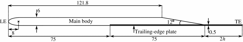
Figure 1. Schematic diagram of the flat-plate model. Dimensions in mm and 2h = 15 and 30mm for the straight and serrated trailing edges, respectively.
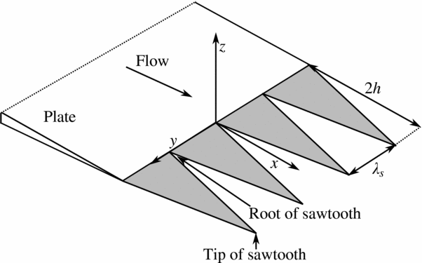
Figure 2. Sawtooth serrations at the trailing edge of a flat plate with root-to-tip amplitude of 2h and wavelength of λ.

Figure 3. The trailing-edge plates and the flat-plate model in situ.
The trailing-edge plate is fastened to the main body with 24 M2 × 0.4 screws. These screws protruded slightly (< 0.4mm) into the flow below the lower flat surface of the plate model; however, this was consistent for all three plate configurations. Hot-wire measurements within the boundary layer on the lower flat surface of the plate, downstream of the screws, confirmed that any flow disturbances created at the screws dissipated well before the trailing edge. The method of trailing-edge attachment used in this study avoids bluntness at the root of the serrations that may produce vortex shedding and a tonal noise component. The flat-plate model was then held between two side plates and attached to the contraction at zero angle-of-attack, as shown in Fig. 3(b).
Figure 3(b) shows the span of the flat-plate models extends beyond the width of the contraction outlet. This was done to eliminate the noise produced by the interaction of the side-plate boundary layers with the model leading edge. To determine the influence of this mounting method on radiated noise, the acoustic spectra of two different reference-plate models (with straight trailing edge) have been previously compared by the authors(Reference Moreau, Doolan, Tetlow, Roberts and Brooks20). One plate had a span equal to the width of the contraction outlet (275mm) and was held between two side plates that were aligned with the contraction edges. The second plate had a span of 450mm, as shown in Fig. 3. The noise radiated by the two plates was found to be highly comparable over the entire frequency range of interest from 250Hz to 10kHz.
2.2 Anechoic wind-tunnel facility
Experiments were performed in an anechoic wind tunnel located at the University of Adelaide(Reference Leclercq, Doolan and Reichl21). The anechoic wind-tunnel test chamber is 1.4m × 1.4m × 1.6m (internal dimensions) and has walls that are acoustically treated with foam wedges, providing a near reflection-free environment above 250Hz. The facility contains a contraction outlet that is rectangular in cross-section with dimensions of 75mm × 275mm. The maximum-flow velocity of the free jet is approximately 40m/s and the free-stream turbulence intensity at the contraction outlet is 0.33%(Reference Moreau, Brooks and Doolan22). In this study, experiments were conducted at free-stream velocities between U ∞ = 9 and 12m/s corresponding to Reynolds numbers Re c = 1 × 10⁵ and 1.3 × 10⁵, respectively.
2.3 Measurement techniques
Acoustic measurements were recorded at a single-observer location using a B&K 1/2” microphone (Model No. 4190), located 554mm directly below the trailing edge of the reference plate. Hot-wire anemometry was used to obtain unsteady velocity data in the wake of the serrated- and reference-plate models. A TSI 1210-T1.5 single-wire probe with wire length of L = 1.27mm and a wire diameter of d = 3.81μm was used in experiments. The sensor was connected to a TSI IFA300 constant temperature anemometer system and positioned using a Dantec automatic traverse with 6.25μm positional accuracy. The traverse allowed continuous movement in the stream-wise (x), span-wise (y) and vertical (z) directions. The co-ordinate system used in this study is shown in Fig. 2 and is located at centre span at the root of the trailing-edge serrations. Acoustic and flow data were recorded for each flat-plate model using a National Instruments PCI-4472 board at a sampling frequency of 5 × 10⁴Hz for a sample time of 8s and 4s, respectively. Data are presented in narrowband format with a frequency resolution of 2Hz and have been calculated using Welch’s averaged modified periodogram method of spectral estimation with a Hamming window function and 75% overlap. The 95% confidence interval(Reference Bendat and Piersol23) on the narrow-band power density is −0.79/+0.85dB/Hz for the acoustic measurements and −1.4×10⁻⁶/+8.0×10−6m2/s for the velocity measurements. Additionally, the error in the mean velocity estimates is 0.32%.
3.0 EXPERIMENTAL RESULTS
3.1 Acoustic measurements
Figure 4 shows acoustic spectra for the reference plate and the plates with trailing-edge serrations at flow speeds of U ∞ = 9 to 12ms−1. The background noise spectra which indicate the tunnel noise levels without the plate present are also shown in this figure for comparison. The spectra in Fig. 4 have been plotted with the x-axis indicating both frequency in kHz and Strouhal number, St 2h , based on serration root-to-tip amplitude, 2h. While noise spectra are presented at a single-observer location only, trailing-edge serrations have not been found to modify the directivity of the noise radiated by a straight trailing edge(Reference Moreau and Doolan17).

Figure 4. Far-field acoustic spectra for the reference plate and the plates with trailing-edge serrations at U ∞ = 9to12m/s. The background spectra indicate the tunnel noise level without the plate present.
Figure 4 shows that the noise produced by the reference plate at all flow speeds is broadband in nature. The low-frequency noise levels of the reference plate (below 500Hz) are observed to increase in amplitude with decreasing flow speed.
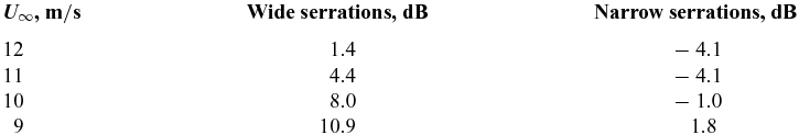
The wide serrations are shown in Fig. 4 to produce broadband noise levels and a low-frequency region of attenuation that increases in amplitude with decreasing flow speed. A reduction of up to 16dB is achieved in the narrowband noise levels with the wide serrations (see Fig. 4(d)). The low-frequency region of noise attenuation is bounded by a Strouhal number based on serration root-to-tip amplitude, 2h, of St 2h = 6.4. Table 1 states the reduction in overall sound pressure level between 250Hz and 4kHz, achieved with trailing-edge serrations at flow speeds between U ∞ = 9 and 12m/s. This table shows that the wide serrations reduce the overall sound pressure level by up to 11dB.
Table 1 Reduction in overall sound pressure levels between 250Hz and 4kHz with the trailing-edge serrations.

The far-field noise spectra in Fig. 4 show that the narrow serrations produce regions of increased acoustic amplitude with two distinct tones. The narrow serrations increase the narrow-band noise levels by up to 14dB (see Fig. 4(b)) and produce an increase in the overall sound pressure level at flow speeds between U ∞ = 10 and 12m/s, as shown in Table 1. The two tones produced by the narrow serrations occur at a constant Strouhal number of St 2h = 1 and 1.3. Above a Strouhal number of St 2h ≈ 2, the narrow serrations are shown to perform similarly to the wide serrations.
The authors have previously examined the effect of trailing-edge serrations on a flat plate at higher flow speeds of U ∞ = 15 to 38m/s(Reference Moreau and Doolan17), using the same experimental set-up and flat-plate models as in this study. Figure 5 shows the narrow-band far-field acoustic spectra for the reference plate and the two plates with trailing-edge serrations at flow speeds of U ∞ = 15 and 38m/s. The background noise spectra are also shown in this figure for comparison. At flow speeds of U ∞ = 15m/s and above, both the narrow and wide, serrated trailing edges produce broadband noise and achieve reductions of up to 13dB in the narrow-band noise levels (in the high-frequency region between 5 and 10kHz at U ∞ = 38m/s and between 1.5 and 4.5kHz at U ∞ = 15m/s). Trailing-edge serrations that are effective at reducing noise at higher Reynolds numbers may, therefore, produce undesirable tonal noise during low Reynolds number operation.
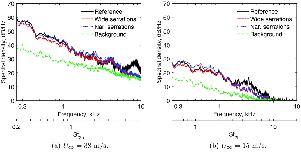
Figure 5. Far-field acoustic spectra for the reference plate and the plates with trailing-edge serrations at U ∞ = 15 and 38m/s. The background spectra indicate the tunnel noise level without the plate present.
3.2 Velocity measurements
The normalised mean (U/U ∞) velocity profiles measured in the very near wake of the reference plate and the two plates with trailing-edge serrations at free-stream velocities between U ∞ = 9 and 12m/s are shown in Fig. 6. The profiles for the reference plate have been measured at x/c = 0.1, which corresponds to 1mm downstream of the straight trailing edge, while for the two plates with trailing-edge serrations, the profiles have been measured at x/c = 0.19, which corresponds to 1mm downstream of the tip of a serrated tooth.

Figure 6. Normalised mean velocity profiles at the trailing edge. The profiles for the reference plate have been measured at a position of x/c = 0.1, which corresponds to 1mm downstream of the straight trailing edge. The profiles for the plates with trailing-edge serrations have been measured at the tip of a serrated tooth at a position of x/c = 0.19, which corresponds to 1mm downstream of the serrated trailing edge.
At each flow speed, the velocity profiles for the three trailing-edge geometries in Fig. 6 differ significantly. This indicates that trailing-edge serrations alter the flow structure in the very near wake. The velocity profiles of each plate are qualitatively similar at flow speeds between U ∞ = 9 and 12m/s, indicating that the same flow regimes are present at the trailing edge of each plate at all flow speeds.
The mean velocity profiles for the reference plate in Fig. 6 are highly asymmetric about the trailing edge. The mean velocity profiles for the reference plate at U ∞ = 9 and 12m/s are compared with the Blasius solution(Reference Cebeci and Bradshaw24) in Fig. 7. Below the trailing edge, the profiles are highly comparable to the theoretical Blasius profile, indicating that the flow is laminar throughout the boundary layer. On the top surface, the profiles display a more laminar inner region with significant deviation in the outer region of the boundary layer. This suggests that the laminar boundary layer separates at the bevel and then reattaches as a transitional boundary layer on the straight trailing-edge plate, just upstream of the trailing edge. The deviation in the outer boundary-layer region is associated with the growth of the separated shear layer over the bevel. The high levels of low-frequency noise observed for the reference plate in Fig. 4 are most likely due to eddies or flow perturbations in the transitional boundary layer on the top surface of the plate near the trailing edge. At lower flow speeds, the boundary layer will contain more spatially coherent eddies than at higher flow speeds, thus resulting in higher levels of low-frequency noise(Reference Moreau, Brooks and Doolan25).
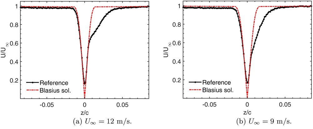
Figure 7. Normalised mean velocity profiles at the trailing edge of the reference plate compared to the Blasius solution. The profiles for the reference plate have been measured at a position of x/c = 0.1, which corresponds to 1mm downstream of the straight trailing edge.
Figures 6 and 7 show the flat-plate boundary layer remains in a similar laminar-transitional state at flow speeds of 9 to 12m/s. When the flow is in a laminar-transitional state, instabilities, known as Tollmien-Schlichting (T-S) waves, are present in the boundary layer. Sound is produced by the scattering of these boundary-layer instabilities at the trailing edge(Reference Arbey and Bataille26-Reference Chong and Joseph28). The frequency distribution of T-S waves in the boundary layer is sensitive to small changes in Reynolds number, and for this reason, flow-speed variation is observed in the spectral shape and amplitude of the radiated noise in Fig. 4.
Figure 6 shows the wake of the plate with wide serrations is characterised by a slightly asymmetric velocity field. In comparison, the mean velocity profiles for the narrow serrations are largely symmetric about the trailing edge. Additionally, the profiles show the velocity deficit is more quickly recovered along the wake centerline for the plate with narrow serrations.
As the source of trailing-edge noise is the unsteady flow field about the trailing edge, time-varying flow data have been measured along the span in the near trailing-edge wake for each model. Velocity measurements are presented at the selected flow speed of U ∞ = 11m/s only as the results are qualitatively similar at all flow speeds between U ∞ = 9 and 12m/s.
Figure 8 shows spectral maps of the fluctuating velocity (u′2/Hz) measured in the span-wise (y) direction along the trailing edge at a distance of 1mm downstream from both the straight and serrated trailing edges. Figure 8(a) shows that the wake velocity field close to the trailing edge of the reference plate is comprised of broadband random velocity fluctuations across the span. High energy is observed at low frequencies, and this corresponds to the high levels of low-frequency trailing-edge noise shown in Fig. 4.

Figure 8. Velocity spectral maps measured in the span-wise (y) direction inline with the trailing edge at U ∞ = 11m/s at a position of 1mm downstream (at x/c = 0.1, z/c = 0 for the reference plate; and, at x/c = 0.19, z/c = 0 for the plates with trailing-edge serrations). In (b) and (c), a position of y/c = 0 corresponds to the tip of a serrated tooth.
The spectral maps, measured in the near wake of the two plates with serrated trailing edges in Figs 8(b) and (c), show features that occur due to flow interaction with the serrations. These results also show that the trailing-edge serrations affect the flow field in the vicinity of the trailing edge, which is the source of the trailing-edge noise in Fig. 4.
The spectral maps for the flat plate with narrow serrations in Fig. 8(c) display high-intensity velocity fluctuations at the same frequencies as the two tones observed in the corresponding far-field noise spectrum (see Fig. 4(b)). The high-intensity velocity fluctuations at the tonal noise frequencies in the wake are attributed to vortex shedding from the tips of the serrated teeth. Figure 8(c) shows that the narrow serrations permit intense vortex shedding across the span, which results in the production of high-amplitude tonal noise. High energy fluctuations also exist in the space between the narrow, serrated teeth (e.g. at a frequency of 900Hz or St 2h = 2.6 in Fig. 8(c)), which corresponds to the first harmonic of the second, higher-frequency tone in the far-field noise spectrum (see Fig. 4(b)). While no defined peak is observed at this frequency in the noise spectrum, a broad hump is visible at this frequency.
The spectral maps for the plate with wide serrations in Fig. 8(b) show weak vortex shedding also occurs from the tips of the wide serrations. This vortex-shedding process is low in amplitude and does not result in tonal noise production (see Fig. 4).
3.3 Discussion
At flow speeds of U ∞ = 9to12m/s, both serration geometries are effective at reducing low-frequency noise between a Strouhal number of St 2h = 1.4 and 6.4 (see Fig. 4). The wide serrations outperform the narrow ones by achieving attenuation at all frequencies below St 2h = 6.4. The narrow serrations do not reduce noise below St 2h = 1.4, where it is intensified into two discrete tones at St 2h = 1 and 1.3.
The narrow serrations exhibit a symmetric wake profile (see Fig. 6), indicating that the boundary layers on the top and bottom surface of the trailing edge separate evenly and permit coherent vortex shedding in the wake. The narrow serrations have the same effect on the acoustic and flow field as the wide serrations at high frequencies (St 2h ≈ 2), but vortex shedding occurs from the tips of the serrated teeth at low frequencies, resulting in high-amplitude acoustic tones (see Fig. 8(c)).
The wide serrations produce a slightly asymmetric wake profile (see Fig. 6), and correspondingly, weak vortex shedding occurs at the tips of the wide, serrated teeth (see Fig. 8(b)). The vortex shedding is low amplitude and does not result in tonal noise production. A low-frequency noise reduction is achieved with the wide serrations, as they reduce the low-frequency turbulence levels at the trailing edge (see Fig. 8(b)).
At flow speeds of U ∞ = 15m/s and above, the tonal noise produced by the narrow serrations is suppressed and they produce broadband noise only (see Fig. 5). Figure 9 shows the normalised mean velocity profiles at the trailing edge of the plate with narrow serrations at flow speeds of U ∞ = 12 and 15m/s. This figure shows that when the flow speed is increased to U ∞ = 15m/s and the flow is more turbulent, the narrow serrations produce a highly asymmetric wake profile. Vortex shedding is suppressed in this case and only broadband noise production occurs.
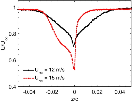
Figure 9. Normalised mean velocity profiles at the trailing edge of the plate with narrow serrations at U ∞ = 12 and 15m/s. The profiles have been measured at the tip of a serrated tooth, at a position of x/c = 0.19, which corresponds to 1mm downstream of the serrated trailing edge.
4.0 CONCLUSION
This paper has presented results of an experimental study on the effect of trailing-edge serrations on a flat plate at low Reynolds numbers. The wide trailing-edge serrations with wavelength to amplitude ratio of λ s /h = 0.6 were found to reduce the overall sound pressure level by up to 11dB. In contrast, the narrow trailing-edge serrations with λ s /h = 0.2 produced high-amplitude tonal noise and an increase in the overall sound pressure level. Unsteady flow data in the near-trailing-edge wake showed that the narrow serrations permit the formation of intense vortices at each serration tip, resulting in the production of high-amplitude tonal noise, while the wide serrations reduce the turbulence at low frequencies resulting in an overall noise reduction.
The results show that serrations affect the flow structure at the trailing edge and that these changes are more important than any reduction in acoustic radiation efficiency. The results also have important practical implications. Serrations that are effective at a high Reynolds number may produce unwanted tones when operated at off-design conditions or during low Reynolds number operation. Thus, care is needed to fully understand the flow field over serrations for all intended operating conditions.