


Nomenclature
- AAL
Above Aerodrome level
- AGL
Above Ground level
- CDI
Course Deviation Indicator
- DME
Distance Measuring Equipment
- FTE
Flight Technical error
- GBAS
Ground-Based Augmentation System
- GNSS
Global Navigation Satellite Systems
- ILS
Instrument Landing system
- NSE
Navigation Sensor error
- PBN
Performance-Based Navigation
- RNAV
Area Navigation
- RNP
Required Navigation Performance
- SBAS
Satellite-Based Augmentation System
- TSE
Total System Error
- VOR
Very High-Frequency Omnidirectional Range
1.0 INTRODUCTION
Conventional airways are defined through the connection of ground-based radio navigation aids, most commonly the very high-frequency omnidirectional radio range (VOR) and distance measuring equipment (DME)( Reference Forssell 1 ). Due to their fixed location in space, this limits the number of available routes in the network formed by these beacons. Naturally, using a limited network will always be less efficient than routing via direct great circle connections between origin and destination. With the advent of global navigation satellite systems (GNSS)( Reference Misra and Enge 2 ), their global availability plus the subsequent approval of most states to use GNSS as primary means of navigation for all phases of flight, the opportunity for a more dynamic route planning and free route airspace have become available to the aviation community. Compared with conventional area navigation (RNAV), based on the lines of position from VOR/DME stations, satellite navigation provides much a higher flexibility, accuracy and availability. Moreover, it allows monitoring of the position solution through receiver autonomous integrity monitoring techniques( Reference Walter and Enge 3 ). In fact, certification of a GNSS navigation device for navigation under instrument flight rules requires continuous integrity monitoring to ensure the proper navigation performance.
Besides the most commonly used NAVSTAR GPS( 4 ), other GNSS such as GLONASS( 5 ), GALILEO( 6 ) and Beidou exist or are in the process of achieving full orbital constellations. To increase coverage, some countries have established regional satellite navigation systems (Indian regional navigation satellite system IRNSS and the Japanese quasi zenith satellite system QZSS) that complement other GNSS. Augmentation systems based on differential corrections provide higher accuracy and integrity in a local area (ground-based augmentation system (GBAS)( Reference Dautermann, Felux and Grosch 7 – 10 ), or a specific wider region (satellite-based augmentation system (SBAS)( Reference Dautermann 11 – 13 )). Giving credit to the multitude of a combination of position sources including hybridisation of different technologies (like inertial navigation-aided GNSS receivers( Reference Titterton and Weston 14 , Reference Groves 15 )), the International Civil Aviation Organization (ICAO) introduced the performance-based navigation (PBN) framework. It sets the requirements for a specific airspace or procedure rather than on the equipment used for it. As long as the aircraft can fulfill these requirements, it is less important in which way the compliance is achieved. The relevant ICAO DOC9613( 16 ) specifies the requirements applying to the total system error (TSE) of the aircraft path following capabilities. The TSE consists of the three major components flight technical error (FTE), navigation system error (NSE) and path definition error (PDE) which are additive( Reference Geister, Dautermann, Mollwitz, Hanses and Becker 17 ) in the sense of Gaussian random variables.
One current implementation of PBN is called required navigation performance (RNP( Reference Kelly and Davis 18 )) and usually specified with a numerical value expressing 95% of the aircraft lateral total system accuracy requirement in nautical miles. For example, RNP 4 means that the aircraft must be certified to maintain a track within 4 miles to the left and the right as well as along the track during 95% of the time. Usually, the pilot is provided with a course deviation indicator (CDI) which shows the rectilinear cross-track deviations from the desired track. For the vertical component, the aircraft uses a barometric altimeter to determine its height above a designated pressure surface. The vertical TSE is not covered under RNP, but altimeter NSE accuracy requirements are specified. RNP can be used for aircraft instrument approaches to guide the aircraft to a safe landing on a runway (Fig. 1 (c)). When used in this manner, the RNP usually begins with 1 nm at the beginning of the approach and scales down to 0.3 NM on the final approach. Nevertheless, an RNP approach (abbreviated RNP APCH) is a non-precision approach, meaning that the actual landing must be performed manually by the pilot starting at higher altitudes than during a precision approach. Figure 1 shows (a) a vertical profile of a precision approach: glide path and maximum allowed deviations form a cone. Prior to intercept, the vertical profile is maintained according to the barometric altimeter; (b) the lateral profile of a precision approach: localizer beam and maximum allowed deviations form a cone. Prior to intercept of the localiser beam, navigation is according to the directional gyro; (c) the lateral profile of a non-precision approach according to RNP. Designed path and linear deviations form a narrowing tube. For the classical RNP approach, the vertical navigation is purely barometric according to the altimeter indication.
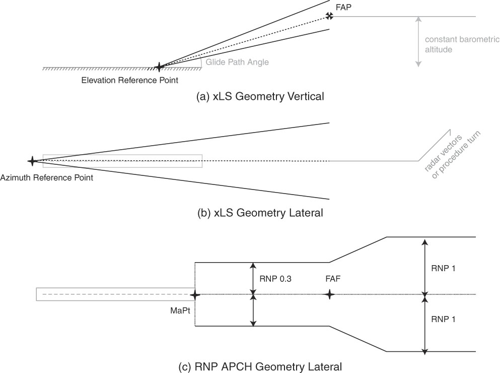
Figure 1 Angular precision approach (ILS, MLS or GLS) in comparison with an RNP approach. (a) Vertical profile of a precision approach: Glide path and maximum allowed deviations form a cone. Prior to intercept, the vertical profile is maintained according to the barometric altimeter. (b) Lateral profile of a precision approach. Localiser beam and maximum allowed deviations form a cone. Prior to intercept of the localiser beam, navigation is according to the directional gyro. (c) Lateral profile of a non-precision approach according to RNP. Designed path and linear deviations.
To fly an RNP APCH, the aircraft must be equipped with a suitable and current navigation database in the ARINC424 Standard( 19 ). This standard defines “path terminators”, i.e. points in space accompanied by routes leading there. To describe such a point in space, often the word “fix” is used in aircraft procedures (while, nowadays, it generally describes a way point, the name originates from a time where a vehicle’s position was fixed in space by means of intersecting lines of position). As an example, the track-to-fix path terminator contains a ground track value and a location to reach (“leg end point”, or “fix”) on this track. The document governing air navigation procedure design( 20 ), section III-2-5-1, suggests to use only a certain subset of path terminators for RNP approaches, namely Initial Fix (IF), Track to Fix (TF), Radius-to-Fix (RF) and Mandatory Hold (HM) in order to avoid discontinuities in the lateral approach path. Further details on the coding and an overview of all leg types can be found in Aeronautical Radio Inc.( 19 ). As an extension to the RNP concept, the recent issue of ICAO( 16 ) introduces the possibility to fly curved segments with a predefined track angle change and curve radius during an instrument approach, summarised under the advanced RNP concept (Fig. 1(c)). Before the advent of advanced RNP, only straight segments were usable for classical RNP or RNAV operations. Since an aircraft cannot make abrupt course changes, the transitioning between two straight segments was not well defined. This leads to a different ground track for each aircraft type/flight management system (FMS) and wind vector combinations. The new leg type to enable precise path following during the curved segments is the previously mentioned RF. It begins at a previous fix, follows a circle with a predefined radius and centre and ends at the beginning of the next segment. Exit track angle of the RF must be the same as the one of the following leg and entry track angle the one of the preceding leg in order to avoid discontinuities in path steering.
On the contrary, a precision approach requires angular guidance in the lateral and the vertical direction to the runway in the shape of a funnel. It has to be referenced to geoidal altitude. Consequently, deviations become more sensitive to lateral and vertical motion as the aircraft approaches the runway, and a higher accuracy is achieved the closer vehicle gets to the runway (Fig. 1(a) and (b)). Modern transport aircraft can perform automatic landings from such a precision approach. Three such precision approach systems are available on the market to airport operators: the microwave landing system (MLS), the GPS Landing System (GLS) and, most commonly used, the instrument landing system (ILS). Details on these systems can be found in ICAO Annex 10 Aeronautical Telecommunications( 21 ). Before intercepting the final precision approach cone, the aircraft usually navigates on a course to intercept, possibly supported by radar vectors from an air traffic controller, and at fixed barometric altitudes. In order to optimise approach procedures, an apparent solution is to combine a final precision approach segment with RNP feeder, initial and intermediate approach segments. Track angles will be changed by connecting straight segments with RF leg. Often, terrain constraints and noise abatement require the final approach segment on the xLS (ILS, GLS or MLS) to be as short as possible with limited space and time to track the straight-in final approach course. Hence, we are especially interested in the case where the RF curve delivers the aircraft directly onto the precision approach. This means that the aircraft is centred on localiser and glideslope at the end of the curved segment, and can commence its guided descent.
Previous studies mainly investigated issues of track keeping performance and FTE (e.g. Refs.( Reference DeSmedt, Robert and Behrend 22 , 23 )). Emphasis was put especially on the altitude performance, i.e. the transition from guidance by the altimeter to vertical guidance provided by the glide slope beam and the ability to deliver the aircraft laterally onto the localiser. The altitude performance was considered especially critical since departures from the standard atmosphere temperature gradients lead to altitude errors. For example, on a warm day, air density is lower and, therefore, the true altitude is higher than the indicated altitude. A procedure designed such that an exact match is achieved between RNP vertical path and xLS glide path in a standard atmosphere will now deliver the aircraft above the glide slope centre beam. In extreme cases, this may cause the autopilot to be unable to capture the vertical path due to its design limits( Reference DeSmedt, Robert and Behrend 22 ). The Single European Sky ATM Research Project (SESAR), work package 9.9, delivered top level RNP to xLS functional requirements( 24 ), architecture( 25 ) and concept of operations( 26 ) (ConOps). The SESAR concept of operations contains recommendations for procedure design. Among those, the requirement for automatic landings states that a minimum final approach segment of 5 Nautical Miles (NM) is required due to “current autoland laws technical constraints (mainly the integrator settling times)”. Moreover, it also envisions a final approach segment of less than 3 NM and an xLS joining as low as 500ft for future operations. The SESAR ConOps reports a set of simulator validation exercises with the shortest final approach segment being 3 NM. The outcome of these is positive, but significant differences were found between aircraft types. Some more details of the simulations can be found in SP WP9.9( 23 ). Unfortunately, none of the SESAR RNP2xLS documents is available to the public. Results of SP WP9.9 ( 23 ) are published as in DeSmedt et al.( Reference DeSmedt, Robert and Behrend 22 , Reference DeSmedt, Robert and Behrend 27 ) which conclude that for all simulated aircraft, a direct transition from the curved segment was possible without the need for a straight intermediate segment. DeSmedt et al.( Reference DeSmedt, Robert and Behrend 27 ) mention that the absence of a straight intermediate segment often required pilot intervention, but does not state whether the crew perceived this as high workload. DeSmedt et al.( Reference DeSmedt, Robert and Behrend 22 , Reference DeSmedt, Robert and Behrend 27 ) discouraged the use of any intercepts of the localiser closer than 5 NM (1500 ft) from the threshold due to aircraft stabilisation issues in various conditions and for various ranges of equipment tested. The performance-based rulemaking committee (PARC) of the Federal Aviation Administration of the United States of America published RNP2xLS recommendations in 2014( 28 ). These require a segment shallower than the glide path of the xLS of at least 1NM length, and a maximum track angle change of the curved segment ending at the final approach course fix to be 180° or less.
In our study, we flight tested experimental RNP 2 ILS approaches to see the limits and capabilities of the A320 aircraft D-ATRA, owned by the German Aerospace Center (DLR). The approach mode of the autopilot could be armed upon reaching the final approach point with an immediate transition to active mode. Alternatively, the mode could be armed before with the expected negative consequence of experiencing a dogleg deviation from the prescribed track increasing the flight technical error. Besides the items of the previous simulator studies( Reference DeSmedt, Robert and Behrend 27 ), we considered additional points of interest. Even though automatic landings are one of the most safety critical certifications in aviation, little is known outside the manufacturer's test departments about the limits of such a system. Here, we intended to focus on the altitude above the aerodrome at which the RF leg can deliver the aircraft on an ILS beam while automatic landings are still possible.
Second, we try to fly the approach as a continuous descent approach using altitude constraints and vertical path angles coded in the database of the flight management system as a part of the ARINC424 path terminators. Different combinations of constrains at waypoints and vertical path angles have the potential to lead to vastly different behaviour of the FTE. This manuscript is not thought to provide a new concept of operations and neither does it suggest that any of the procedures tested should be operationally implemented without the proper safety case and hazard assessments. The experiments merely explore the limits of what can technically be done today and how and an open mind can perceive as future trajectory optimised operations. As we focused on the vertical performance, lateral deviations are not investigated here.
2.0 INSTRUMENT APPROACH PROCEDURE DESIGN
An instrument approach procedure describes the last phase of a flight. It is defined as the trajectory an aircraft should follow from the initial approach fix (IAF) to the decision altitude or missed approach point. It is composed of initial, intermediate and final approach and, if necessary, the missed approach segments. The initial approach is the segment from the IAF to the intermediate fix (IF). Here, the aircraft departs from the first navigation aid or fix to begin the procedure intended to conclude with a landing.
The intermediate approach is placed between IF and final approach fix (FAF) or final approach point (FAP). Here, initial course alignment towards the final approach course and configuration of the aircraft for landing should be achieved.
As the last part of the approach, before either a landing or a missed approach, the final approach procedure is performed. It is located between the FAF/FAP, and the decision altitude for precision approaches or the missed approach point for non-precision approaches. Final course alignment and descent for landing make up the key indicators of the final approach segment.
Lastly, the missed approach segment needs to be executed if the conditions for a successful landing are not fulfilled. The aircraft then returns to the terminal area usually climbing back to a safe holding altitude. From here, it can divert to a different suitable airport or retry the approach.
In order to be able to test experimental procedures, the approach paths had to be coded ARINC 424 conformal and added to the navigation database of the FMS of the ATRA test aircraft. The ARINC 424 format standardises storage and exchange of navigation data in airborne navigation systems. The current database provider for the ATRA is Lufthansa Systems – LIDO which supplemented the navigation database with our novel trajectories. In this way, all of the new approaches were selectable prior to the flight tests by the pilots via the standard input device MCDU. Each approach description contains a series of waypoints that are defined by latitude and longitude. They end at the threshold of the corresponding runway. A waypoint is denoted by a five-digit/letter identifier. It can be part of multiple routes and procedures. The role of a waypoint in a particular navigation application, i.e. the leg type that leads to the waypoint, is denoted by a path terminator. A certain approach type can also feature multiple IAFs in order to provide a more flexible access to the procedure (e.g. a northerly and one southerly IAF for an ILS approach).
Here, we coded a set of five experimental RNP to ILS approaches for runway 26 of Braunschweig-Wolfsburg airport as ILS precision approach procedures. Each approach includes an RF leg terminating on the ILS intercept point at different heights between 550ft and 2000ft above ground level. This resulted in a final approach length between 1.73 and 6.28 nautical miles. The individual approaches are named ILS S through ILS W. They feature greater ILS intercept heights with ascending alphabetical order. Details on intercept heights and length of the final approach segment can be found in Table 1. Each approach includes four initial approach fixes (IAF) that are connected to the entry point of the RF leg using a TF leg. The IAFs are placed such as to result in a track angle change in the RF leg of 30°, 60°, 90° or 180°. During the RNP part of the approach, i.e. up to the ILS intercept point, the vertical profile is designed to feature a constant descent with a flight path angle of –2° starting at the IAF. The approaches ILS S through ILS V start in an altitude of 4000 ft above sea level, whereas ILS W starts in 5000 ft above sea level in order to provide a straight leg with a length sufficient for alignment prior to the entry point of the RF leg. An overview of the approach design is shown in Fig. 2 in a manner similar to the approach charts presented to the pilots. Figure 2(a) shows the lateral profile as seen from the top. Four different approaches with different track angle changes during the RF turn were coded. Each IAF is associated with a different combination of altitude constraints and vertical path angle coded into the ARINC424 path terminator. Figure 2(b) shows the vertical profile to the glide path intercept at xFACF. A 2° descent begins at the initial approach fix transitioning into the 3° ILS. Along track distance depends on the altitude required at the IAF, which is 5000 ft MSL for the ILS W and 4000 ft MSL for all others.
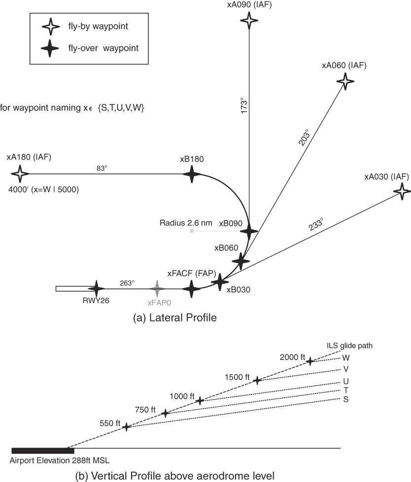
Figure 2 Approach design of the RNP to ILS approaches into Braunschweig-Wolfsburg airport. (a) The lateral profile as seen from the top. Four different initial approach fixes with different track angle changes during the RF turn were coded. Each IAF is associated with a different combination of altitude constraints and vertical path angle coded into the ARINC424 path terminator. (b) Vertical Profile to the glide path intercept at xFACF. A 2° descent begins at the Initial approach fix transitioning into the 3° ILS. Along track, distance depends on the altitude required at the IAF, which is 5000 ft MSL for the ILS W and 4000 ft MSL for all others.
Table 1 Experimental approach design parameters

The five-digit waypoint identifiers were chosen to allow a clear identification of both the approach and the individual path that the waypoint belongs to. They are composed of two alphabetical and three numeric characters identifying the approach. The first alphabetical character is the designator of the approach {S,..,W}, the second character describes the placement in the waypoint sequence, and the three digits signify the track angle change during the RF leg.
It is notable that the ARINC 424 standard in its current version does not foresee the possibility of an RF leg terminating directly on the ILS intercept point. Quality assurance tools of the database coder require a straight segment before the designated intercept point. This is a legacy issue as International Civil Aviation Organization ( 20 ) requires a 2NM straight segment following a final approach course fix for each ILS approach. As a workaround, we declared the FAP to be a final approach course fix and designated a separate, unused point on the final approach course as xFAP0. The arming and intercept of the ILS is performed in the autopilot. It is independent of the FMS waypoint sequencing. This means that the FMS will automatically sequence to the next waypoint upon overflying of each xFAP0, whilst aircraft guidance is provided by the ILS. In the case of RNP terminating in a GLS approach, neither Aeronautical Radio Inc.( 19 ) nor International Civil Aviation Organization ( 20 ) contains this restriction.
PANS-OPS( 20 ), Volume 2, Part 3, Section 2.4.1.4, defines additional criteria for RF legs that end at the FAF/FAP for non-RNP AR procedures: to not to exceed a track angle change of 45° within an along-track distance of two nautical miles before the FAF, the minimum turn radius is restricted to 2.55 NM. Following the ICAO guideline, we set the turn radius for the RF leg in the experimental approaches to 2.6 NM.
Furthermore, we added altitude constraints to the approach paths as shown in Table 4 exemplary for the ILS V 26. We coded all approaches having an “AT” altitude constraint at the initial approach waypoint xAxx and at xFACF. All approaches begin with an AT altitude constraint at the IAF and end in an AT altitude constraint at the point FACF, where the aircraft is centred on the ILS beams. For the approach path in Fig. 3(a), no additional constraint or vertical path angle is inserted. Figure 3(b) contains both vertical path angle and an AT or ABOVE constraint at the intermediate waypoint. Figure 3(c) is coded only with the AT or ABOVE constraint and, finally, Fig. 3(d) is coded only with vertical path angle. The approaches containing a 180° track angle change do not contain any altitude constraint at xB180. No design vertical path angle is included in the navigation database. Figure 3(b) shows the approaches with a 90° track angle change also containing the AT constraint at the IAF, as well as additionally an “AT or ABOVE” constraint at the beginning of the curve at waypoints xB090 plus vertical path angles for all legs. The approaches with the 60° track angle change contain the “AT” altitude constraint at the IAF xA60 and the “AT or ABOVE” constraint at the intermediate fix xB60. There is no coded vertical path angle (Fig. 3(c)). Lastly, the approaches with the 30° track angle change do not have any constraint at xB60 but coded vertical path angles for all leg types as shown in Fig. 3 (d).
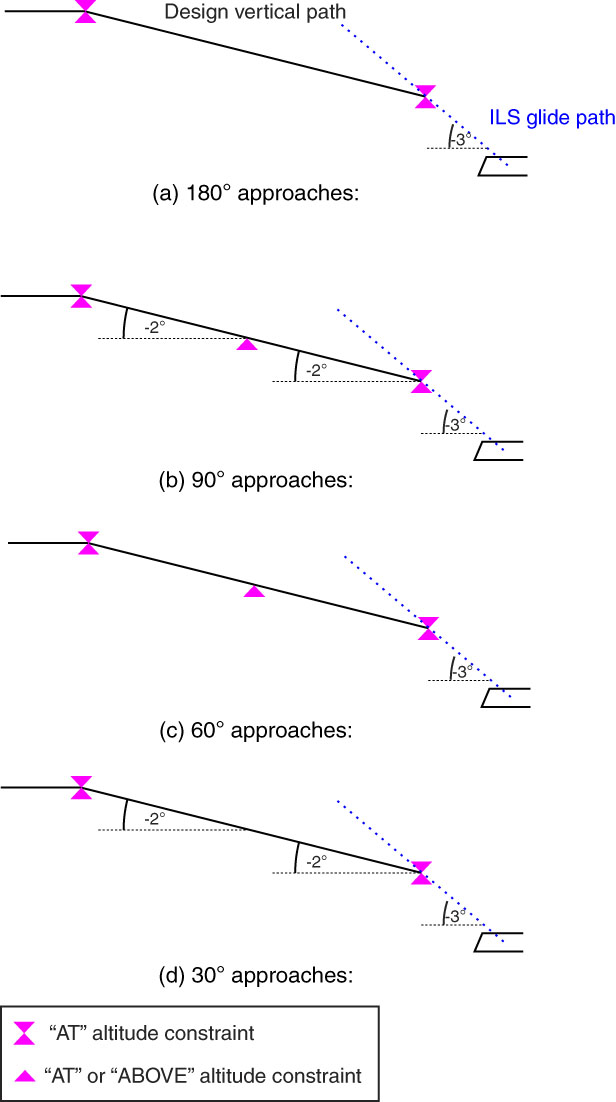
Figure 3 ARINC424 vertical path coding for the different track angle changes within an approach. All approaches begin with an AT altitude constraint at the IAF and end in an AT altitude constraint at the point FACF, where the aircraft is centred on the ILS beams. For (a), no additional constraint or vertical path angle is inserted. (b) Contains both vertical path angle and an AT or ABOVE constraint at the intermediate waypoint, (c) is coded only with the AT or ABOVE constraint and finally (d) is coded only with vertical path angle.
Approaches are designed to follow a –2° descent angle before the ILS glide path intercept, followed by the standard ILS vertical path angle of –3°. From a previous simulator test, we expect an Airbus A320 to follow a dive-and-drive behaviour when adhering to altitude constraints as illustrated in Fig. 4. This means upon passing one constraint, the autothrust would perform an idle descent down to the next constraint altitude. There it would set continuous thrust to maintain that altitude until crossing the point with the constraint. Descent rate is dependent on initial aircraft energy conditions and flap settings, but limited to –500 ft/min by flight guidance computer logic.

Figure 4 The vertical dive-and-drive behaviour expected from Airbus FMS logic.
Lastly, to perform automatic landings from a precision approach, the autopilot and other involved systems of the aircraft are required to meet certain criteria set in Refs ( 29 , 30 ) and( 31 ). A low visibility automatic landing according to CAT III b must always be fail-operational, i.e. two autopilots run in parallel so that a single failure does not cause a catastrophic event( 32 ). The aircraft manufacturer states all necessary operational conditions in the flight crew operations manual (FCOM), for example landing gear down, flaps full, glide slope angle within a certain range and other parameters specific to the aircraft. There is no specific requirement on procedure design to perform automatic landings from an xLS approach.
3.0 FLIGHT TEST SETUP
DLR’s experimental Airbus A320 is equipped with the current Thales FMS2 and a basic Flight Test Instrumentation (FTI). The FTI provides ARINC 429( 33 ) data acquisition from the aircraft’s basic avionics, as well as additional sensors such as precise high-quality GNSS receivers, data storage and real time visualisation of this data to the flight test engineer. It consists of six CRONOS data acquisition units by IMC [(http://www.imc-berlin.com/applications/aerospace/)], three controlling computers and seven display screens for two engineer workstations. From the FTI, a custom data stream can be provided to further experimental stations if needed. All data is recorded at a rate of 20 Hz.
For the RNP to ILS experiments, we used the FTI to record the relevant ARINC 429 data including position, autopilot modes, ILS data, cross track error, altitude and time. The entire experiments were flown using the OEM automatic flight guidance system in a managed mode with only gear, flaps and approach mode arming performed by the pilots.
In order to perform automatic landings with the A320, both autopilots need to be engaged after the approach mode is armed. The automatic flight system will then perform the necessary self-checks and determine its performance. The result will be displayed on the Flight Mode Annunciator (FMA) as either “CAT 2”, “CAT 3 SINGLE” or “CAT 3 DUAL. At a sufficiently low altitude, the mode will switch to LAND mode. At this point, the autopilot can only be disengaged by performing a go-around.
Unfortunately, only very limited information about performance and control laws of the avionics used in the ATRA is available from the manufacturers. It is, therefore, not possible to draw sophisticated conclusions about the actual capabilities of the ATRA regarding RNP to ILS transition in combination with an automatic landing other than the type certifications of the A320 family.
In total, we flew 21 approaches on 5 days, the first approach on the return flight from a different experiment. The main experiments were conducted on 20, 21 and 23 July 2015 and on 5 April 2016 at Braunschweig-Wolfsburg airport in visual meteorological conditions. An overview of all approaches is shown in Table 3.
In 2015, for each ILS intercept altitude from Table 1, we intended to fly one approach with the 180° track angle change, one with 90° track angle change and the approach mode armed at waypoint xA090, and one with the approach mode armed while glide slope and localiser indicators were centred. However, beginning with ILS U 90° (Approach 3), arming the approach mode at the IAF caused the autopilot to lock onto the first side lobe of the localiser signal and the aircraft trying to track towards the runway in approximately 45° relative angle. The approach mode was subsequently cancelled and the aircraft was flown in heading mode back to the desired track. Since all other approach tracks with a lower intercept height were located even closer to the localiser antenna, we also expected side lobe capture and substituted them according to Table 3. Approach #5 was aborted by the pilots for technical reasons. During approach #13, VFR traffic unknown to ATC caused a TCAS Resolution Advisory which prompted the pilots to temporarily level off in order to maintain altitude separation with the intruder. Except for the aborted one (#5), all approaches were completed with an ILS capture on the RF leg and subsequent automatic landings. The test pilots corrected interruptions like the ones caused by the side lobe and the TCAS alert using selected autopilot modes and steered the ATRA back on the desired path afterwards.
In 2016, we completed the trial set by adding in ILS V approaches with the 30° and 60° track angle changes. No unexpected events occurred, but when programming the ILS V 30° into the FMS, the flight crew chose VA030 as fly-over rather than fly-by way point. This resulted in an initial overshoot of the approach alignment leg and subsequent recapture. While in 2015, we performed an automatic landing after each approach, in 2016, the pilots were instructed to go around upon indication of “Land” mode in the flight mode annunciator. Moreover, in 2016, pilots were also instructed to follow the speed guidance as suggested by the flight management system. This means to fly with auto-thrust engaged all the time, and configure the aircraft flaps, slats and gear according to the speed required by the auto-thrust system.
In the managed mode, we expect the aircraft to go through a certain sequence of automatic pilot mode transitions during the RNP2ILS approaches. A subset of the auto pilot modes and their explanation is shown in Table 2. The auto flight system distinguishes lateral and vertical modes separately. For the vertical, we would begin in altitude hold mode and then ideally transition to the geometric path descend mode till the xFACF. There, the aircraft transitions to glide slope capture and then glide slope tracking. When the autoland is active, the landing finishes with flare mode. In sequence, this would be ALT->DES->G/S* ->G/S ->FLARE. Laterally, we begin in navigation mode, followed by localiser capture, localiser track and land mode: NAV->LOC*->LOC->LAND.
Table 2 Autopilot mode relevant to the RNP2ILS flight trials [35]

Table 3 Flight test procedure for RNP to ILS approaches at Braunschweig-Wolfsburg airport

Table 4 Way points, coordinates, vertical path angles and constraints used in the procedure coding for ILS-V

4.0 RESULTS
Figures 5–8 are derived from the approaches flown in 2015. The focus was on the ability to perform automatic landings from a curved ILS intercept. Figures 9–13 stem from the trials flown in 2016. They illustrate the flight technical error and mode transitions for a complete set of approaches with the same glide slope intercept altitude but different ARINC 424 coding tables.
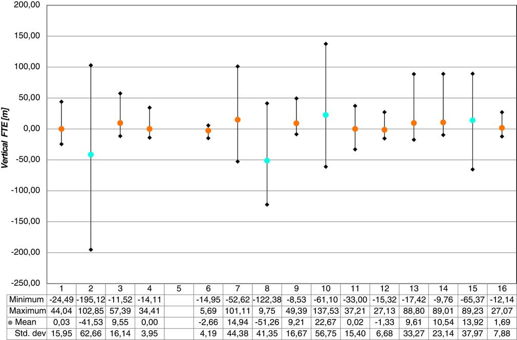
Figure 5 Vertical FTE after the RF leg entry point per approach: for the vertical FTE, a more distinct difference between the approaches coded with and without a flight path angle can be noticed. The 180° approaches (blue), which were coded without a flight path angle, show a higher variation in the vertical FTE due to the “dive-and-drive” behaviour of the FMS. The standard deviation of the vertical FTE clearly shows the influence of the missing flight path angle for the 180° approaches (blue). All 90° approaches (red) that could be completed without incidents such as late clearances display a smaller standard deviation of the vertical FTE. Approach #5 was aborted and is not shown.
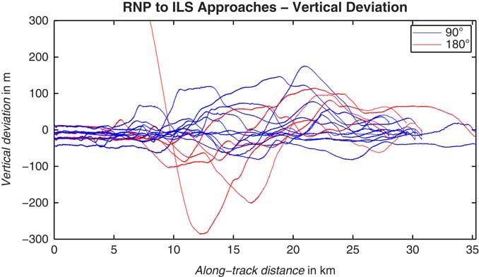
Figure 6 Comparison of vertical deviations during 90° and 180° approaches. The “dive-and-drive” behaviour observed during approaches without a coded flight path angle (red) is clearly recognisable. In comparison to the approaches that include a flight path angle (blue), the vertical path flown by the aircraft is much lower than the intended path during the RF leg if no flight path angle is coded in the navigation database.
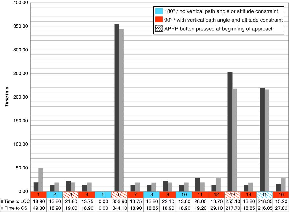
Figure 7 Time between approach mode activation and localiser/glideslope capture. The required time for localiser (red) and glideslope (blue) capture is equally low for all approaches with approach mode activation at the ILS intercept point. In general, the vertical navigation accuracy is the most important factor for a quick transition to ILS guidance as glideslope capture from above is more time-consuming than glideslope capture from below or corrections to the lateral flight path. Approach #5 was aborted and is not shown. Approach 3 was initially flown with the approach mode active early but approach mode was cancelled and reengaged later due to side lobe capture.
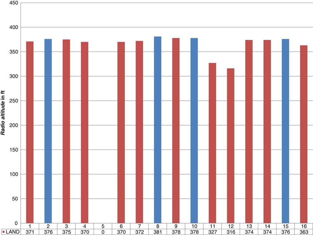
Figure 8 The radio altitude at LAND mode engagement per approach. The radio altitude of the aircraft at LAND mode engagement is nearly identical for both the 180° approaches (blue) and the 90° approaches (red). With the exception of approach #5, which had to be aborted, LAND mode usually engaged between 360 and 380 ft above the ground level. In approaches #11 and #12, during which the ILS intercept point reached slightly high, LAND mode engagement required slightly longer. However, engagement still occurred above 300 ft radio altitude and thus early enough for an automatic landing.
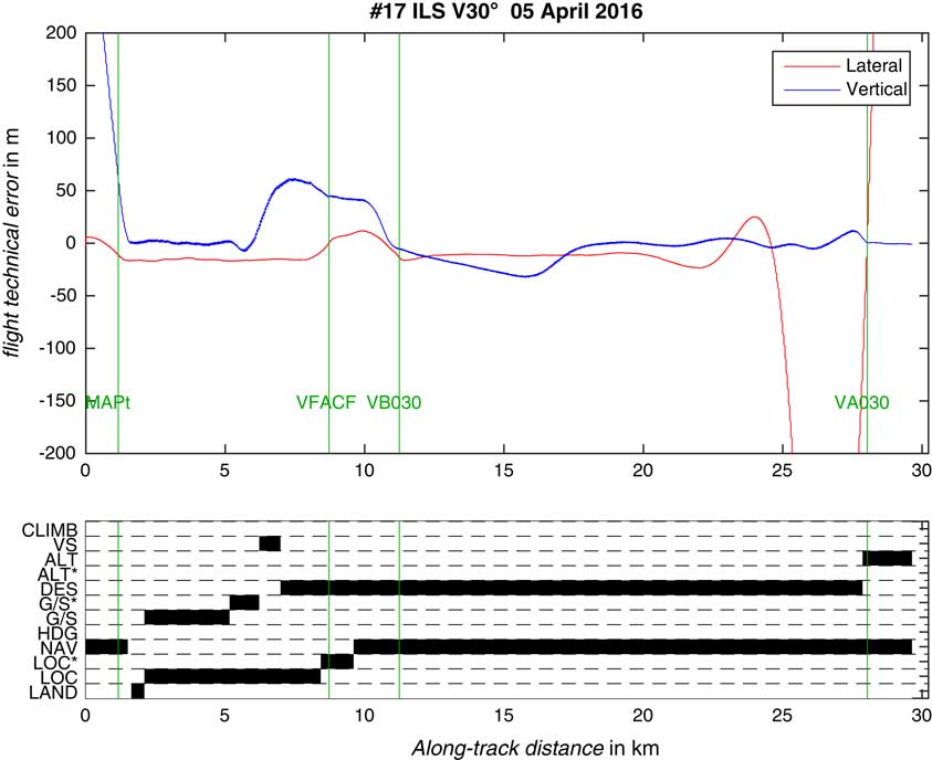
Figure 9 ILS V30 from 5 April 2016. The top panel shows lateral and vertical flight technical error, the bottom panel indicates autopilot modes active during the approach. Green lines mark the approach waypoints. The aircraft arrived slightly high at VFACF which was corrected by the pilot using VS mode. The initial approach fix VA030 was erroneously selected as fly over way point, resulting in an overshoot of the approach trajectory. The automatic flight guidance delivered the aircraft slightly high on the ILS at VFACF which was manually corrected by the pilot using v/s mode.
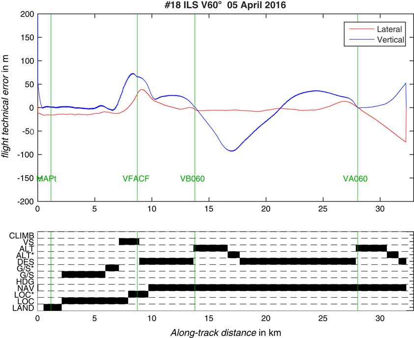
Figure 10 ILS V60 from 5 April 2016. The top panel shows lateral and vertical flight technical error, the bottom panel indicates autopilot modes active during the approach. Green lines mark the approach waypoints. The automatic flight guidance delivered the aircraft slightly high on the ILS at VFACF which was manually corrected by the pilot using V/S mode. Without the vertical path angle coded in the navigation database, the aircraft performs dive and drive between VA060 and VB060.
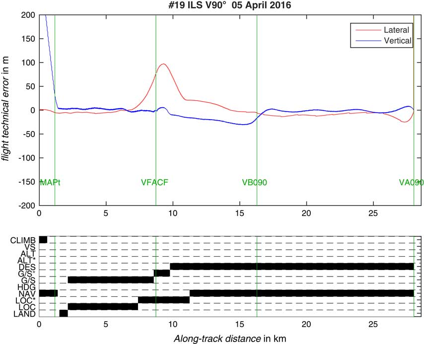
Figure 11 ILS V90 from 5 April 2016 with the approach mode armed at VA090. The top panel shows lateral and vertical flight technical error, the bottom panel indicates autopilot modes active during the approach. Green lines mark the approach waypoints. The cross track error spike slightly before VFACF is caused by early intercept of the localiser.
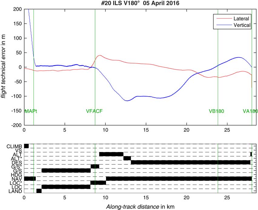
Figure 12 ILS V180 from 5 April 2016. The top panel shows lateral and vertical flight technical error, the bottom panel indicates autopilot modes active during the approach. Green lines mark the approach waypoints. Without the vertical path angle coded in the navigation database and without a constraint at VB180, the aircraft performs dive and drive between VA060 and VFACF.
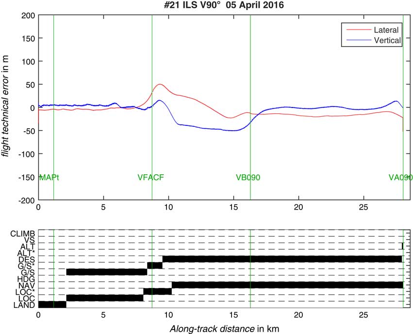
Figure 13 ILS V90 from 5 April 2016 with the approach mode armed at VFACF. The top panel shows lateral and vertical flight technical error, the bottom panel indicates autopilot modes active during the approach. Green lines mark the approach waypoints.
4.1 Vertical Path Following
Figure 5 shows the mean and the standard deviation of the vertical path following error/FTE separately for each approach, colour coded for the 180° and 90° tack angle changes. Recall that the approaches with 180° did not contain vertical path angles or altitude constraints at the intermediate approach fix xB180, whilst the 90° approaches contained vertical path angles in all RF and TF path terminators and an “at or above” constraint at the xB090. We can see that the mean deviations from the designed path are generally negative or below the path. For the vertical FTE, a more distinct difference between the approaches coded with and without a flight path angle can be noticed. The 180° approaches (blue), which were coded without a flight path angle, show a higher variation in the vertical FTE due to the “dive and drive” behaviour of the FMS. However, the mean vertical FTE remains within the acceptable limits (summarised by Dauterman( Reference Dautermann 34 ), 68 m at the 3 sigma level) for all RNP operations when a vertical path and intermediate waypoint constraints were coded in the navigation database. During approaches 7, 13 and 14, external factor such as traffic or late clearances prevented the aircraft from following the optimal path computed by the FMS. The standard deviation of the vertical FTE clearly shows the influence of the missing flight path angle for the 180° approaches (blue). All 90° approaches (red) that could be completed without incidents such as late clearances display a smaller standard deviation of the vertical FTE. Approach #5 was aborted and is not shown.
Moreover, the coding of constraint altitudes and vertical path angles improves the spread of the vertical error visibly. Figure 6 shows the vertical deviations in dependence from along track distance to the runway threshold. Larger departures from the designed path occur during the 180° approaches, in general downwards due to dive and drive planning of the FMS. During the 90° approaches, the mean path following error is also significantly different from zero. The “dive and drive” behaviour observed during approaches without a coded flight path angle (red) is clearly recognisable. In comparison with the approaches that include a flight path angle (blue), the vertical path flown by the aircraft is much lower than the intended path during the RF leg if no flight path angle is coded in the navigation database.
In Fig. 9, it can be seen that the automatic flight guidance delivered the aircraft slightly high on the ILS at VFACF which was manually corrected by the pilot. The initial approach fix VA030 was erroneously selected as fly over way point, resulting in an overshoot of the approach trajectory. Figure 12 shows that without the vertical path angle coded in the navigation database, the aircraft performs dive and drive between VA060 and VB060.
4.2 Mode Transitions
Figures 9–13 show lateral and vertical flight technical error during five different ILS V approaches as well as flight management guidance mode transitions over the along-track distance from the runway threshold. Individual segments are separated by vertical green lines.
In Figs 9 and 11, the aircraft performed a continuous descent but arrived slightly too high above the glide path at VFACF. The experimental pilot used the V/S selected mode for a short descent and then engaged the approach mode. At this point, the FTE analysis shows a vertical error close to zero. Upon capture of the ILS glide path beam, the vertical error is approximately constant at 45 m. The reason for the high arrival was most likely a surface temperature of 15 °C above the international standard atmosphere at Braunschweig-Wolfsburg airport.
Figures 10 and 12 illustrate the dive-and-drive behaviour that was previously mentioned. Between VA060/VB060 and VA180 /VFCAF, respectively, the aircraft performed a descent down to the next constraint altitude in DES mode, and then maintains this altitude until passing the constraint. Then, for the FMS reselects DES mode to proceed to the next constraint altitude in case of ILS V060, or captures the ILS in case of ILS V180. Next, the flight crew selected approach mode on the FCU and the autopilot locked onto the ILS signals. Both approach tracks had no vertical path angle connected to the respective legs in the navigation database.
Lastly, in Fig. 13, we show one approach where the Approach mode of the autopilot was already armed at the initial approach fix. Lateral and vertical mode transitions are the same as in Fig. 11. However, localiser capture occurs earlier causing the aircraft to deviate laterally from the designed path at the order of 100 m. This is the expected dog-legging behaviour, because the ILS guidance loops have converged and are plotting a straight course to intercept the localiser. However, the deviation is small compared with a potentially required RNP of 0.3 NM (555.6 m) laterally.
We show the data from the RNP to ILS V approaches in Figs 9–13 as a representative example for all series of approaches performed in this flight test. The V, U, T and S approaches are qualitative similar with only a lower intercept height and a smaller distance from the xFACF to the runway. The complete set, including a video of the ILS T 90, can be downloaded as Supplementary material.
4.3 Intercept Analysis
Figure 7 shows the elapsed time between approach mode arming and full tracking of localiser and glide slope for each one of the 16 approaches. The required time for localiser (red) and glideslope (blue) capture is equally low for all approaches with approach mode activation at the ILS intercept point. However, for all approaches with approach mode activation at the IAF, the required time depends on the length of the RNP part of the approach. In general, the vertical navigation accuracy is the most important factor for a quick transition to ILS guidance as glideslope capture from above is more time-consuming than glideslope capture from below or corrections to the lateral flight path. Approach #5 was aborted and is not shown. Approach 3 was initially flown with the approach mode active early but approach mode was cancelled and re-engaged later due to side lobe capture. Time is obviously much longer for those approaches that were flown with arming the mode at the initial approach fix (3, 6, 13 and 15). Approach 3 is an exception, where the approach mode was cancelled by the pilots due to an inadvertent capture of a side lobe of the localiser beam.
Due to the localiser antenna as well as signal design, symmetrical side lobes will occur. Typically they are received in an aircraft at ±10°.Footnote 1 The received signal power is usually lower by approx. 13 dB. An aircraft is not able to detect a difference between the side lobe and the main guidance beam. For this reason, the design guidelines of classical approach procedures usually recommend a final approach segment length of 3–10 NM with an optimum of 5 NM with a preceding intermediate approach segment for a safe intercept( 20 ). It is noteworthy to say that the GLS does not exhibit this behaviour. In 7 out of 12 cases in 2015, when the approach button was depressed when localiser and glideslope were approximately centred, the localiser was tracked after about 13.8 s, the glide slope in 8 out of 13 cases after 18.9 s. Since the data were recorded at 20 Hz, the measurement uncertainty is in the order of 0.05 s.
4.4 Automatic Landings
Figure 8 shows the radar altitude at which the LAND mode engaged. The radio altitude of the aircraft at LAND mode engagement is nearly identical for both the 180° approaches (blue) and the 90° approaches (red). With the exception of approach #5, which had to be aborted, LAND mode usually engaged between 360 and 380 ft above the ground level. In approaches #11 and #12, during which the ILS intercept point reached slightly high, LAND mode engagement required slightly longer. However, engagement still occurred above 300 ft radio altitude and thus early enough for an automatic landing.
In all 16 cases when automatic landings were performed, the LAND mode engaged between 316 and 381 ft radar altitude (RA). This is in agreement with Airbus Industries( 35 ) which describes the LAND mode as “Common mode engaged below 400 ft RA during an automatic ILS approach”. During approaches 11 and 12, the aircraft was less than half a dot (0.075°) above the glide path. This may have impacted the guidance loops of the autoland system to require additional time to converge. Thus, the LAND mode activated at a lower altitude as the aircraft descended on the glide path. Even during the ILS S approaches, where the final approach point SFACF is located only 550 ft AAL, the LAND mode engaged at 316 ft radar altitude and 363 ft radar altitude, respectively, indicating quick convergence of the guidance loops in the auto pilot computer.
5.0 CONCLUSIONS
We demonstrated that flying an RNP to ILS approach with automatic landings is technically feasible for our A320, MSN659. In order to perform a continuous and stable descent with the A320 auto flight guidance, it is very important to set constraints and vertical path angles as the trajectory computation prefers a dive-and-drive path outside the final approach segment. We tested all possible combinations of altitude constraints and vertical path angle that are possible in database coding. We found that a combination of constraints and coding of the vertical path angle in each path terminator worked best for our A320 in the given weather conditions. To reduce pilot workload, we recommend arming the approach mode early. However, care must be taken to not cross side lobes of the ILS. For this reason, we recommend to use a GLS whenever possible. Moreover, we need to consider that cross-track error of the autoflight system was assessed only for the A320. When considering other aircraft, this may not necessarily the case. Therefore, if a generalised recommendation has to be made, it is to press the approach button late. In this case, the flight crew must be aware of the workload and required vigilance increase at ILS intercept. Second, when transitioning from RNP to xLS, it is very important to arrive at the glide slope intercept point directly on or slightly below the glide path, as many autopilots require an intercept from this position and may not couple to the glide slope signal when arriving from above. In this case, a manual intervention by the pilot will be necessary and increase workload. Here, we used a 2° RNP descent path, but a shallower one, may be 1° or 1.5° should be more advantageous.
For this experiment, we could only flight test one particular aircraft. As indicated by DeSmedt et al.( Reference DeSmedt, Robert and Behrend 27 ), different aircraft/autopilot combinations may behave vastly different. However, this study was based on simulation data. In the preparation of the RNP2ILS flight trials, we tested all approaches in an A320 full flight simulator at Training Flight Center Käufer in Essen, Germany. Here, for the ILS S approaches, the LAND mode only activated at 180 ft radar altitude compared with 316 ft and 363 ft in the real aircraft. Therefore, care needs to be taken when comparing simulator results to data obtained using a real aircraft, as simulators are to a large part only able to realistically emulate aircraft behaviour in software within the standard operating envelope.
The pilots were comfortable with ILS intercept heights down to 1000 ft AGL. The ILS T and S approaches (with intercept heights of 550 ft AGL and 750ft AGL) appeared to them subjectively less safe since the aircraft was not aligned with the final approach and the runway in sight straight ahead until very late during the approach. The ICAO stabilised approach demands stable and aligned conditions at 1000 ft AGL which is incorporated into pilot training. Therefore, the pilot always expects to be established with the runway centreline at very far distances from the threshold. We should note, however, that the stabilisation criteria were introduced to enhance safety during a time when automatic flight control was not as far advanced as it is today. For manual flight, stabilisation criteria are important and should be maintained. Existing RNP AR operations already include curved segments down to 500 ft AGL( 36 ) with special crew training and show an exemplary safety record. At present, RNP AR formally runs as different concepts of operations and, therefore, does not require the same stabilisation criteria as an ILS approach. However, if both operations are conducted with automatic flight guidance, it is not immediately apparent what the differences in the safety studies between the two concepts are, and why, with RNP AR it would be safer to fly with a turn in 500 ft AGL when compared with an RNP to ILS approach. Instead of the classical ILS stabilisation criteria, for an automatic advanced RNP to precision approaches, a concept similar to “RNP established” ( 37 ) could be considered and supported by safety analyses. Just like with RNP AR, if “things don’t go as expected” at low altitudes, the pilot must initiate a go around and follow the prescribed track to climb back to the minimum safe altitude.
Pilots were not satisfied with the early deceleration of the aircraft when flying in managed speed mode. They indicated that “the early flap configuration resulting in a slow speed approach (in comparison with normal operations/approaches) was not satisfactory with respect to fuel efficiency and ATC management.” This is due to all approaches commencing at distance along the track of more than 15 NM with the continuous descent. However, with the standard procedure design the aircraft will be at a lower altitude earlier during the approach procedure, and thus have an increased potential for noise generation. This, of course, has to be traded off against the noise caused by early deployment of auxiliary flight control surfaces.
SUPPLEMENTARY MATERIAL
To view supplementary material for this article, please visit https://doi.org/10.1017/aer.2018.87
ACKNOWLEDGEMENTS
We would like to thank our DLR pilots Stefan Seydel, Hans-Jürgen Berns, Jens Heider, flight test engineers Adrian Müller and Ludger Tegenkamp, flight technicians Jens Hammer and Silvio Heyne for their support during the flight trials. Furthermore, we are grateful to have been supported by NavArt Aerospace under Marc Altenscheidt through the initial A320 simulator tests. Lastly, we acknowledge the DLR program directorate for aeronautics for providing the necessary funding to conduct the flight tests. Part of this work was conducted as Tobias Blase’s Master’s thesis.


