NOMENCLATURE
- A
tether’s cross section
- b
viscous friction coefficient
- c
damping coefficients
- E
elastic modulus
- f c
frictional force of the tether
- F
thrust force
- F N
normal force
- F T
tether tension force
- F Tref
tension standard
- i
reduction ratio the redactor
- J
moment of inertia of the drum
- k
stiffness coefficients
- K e
torque constant of the motor
- K m
compensation coefficient
- F Tl
tension of the tether leaving the drum
- K Tp
gain in the external loop
- l
nature length of the tether between the mass center of the platform and the target
- L 0
total length of the tether
- L a
terminal inductance of the motor
- m 1
mass of the platform
- m 2
mass of the target
- n
rotate rounds of the roller
- O 1
mass center of the platform
- O 2
mass center of the target
- r
radius of the roller
- r a
terminal resistance of the motor
- R
radius of the drum
- U
terminal voltage of the armature winding
- v 1
velocity of the mass center of the platform
- v 2
velocity of the mass center of the target
- x 1
position co-ordinate of the platform
- x 2
position co-ordinate of the target
- α
angle between tethers
- ξ
length of the tether wound on the drum
- δ
elastic deformation of the tether
- φ
rolling angle of the tether
- η
efficiency of the redactor
- σ
damping parameter
- ω e
mechanical palstance of the rotor
- ω l
angular velocity of the drum
- τ c
coulomb friction torque imposed on the drum
- Δv
velocity difference between the mass center of the platform and the target
- Δv ref
velocity difference demand
1.0 INTRODUCTION
Tension control of the tether, which involves tension tracking and maintaining dynamic tether tension, is one of the basic tasks for the STC after target capture by the TRS. The operational capability and effectiveness of the TRS depend directly on the control performance of the tension control device, as well as the tension control strategies. The STC is a typical rigid-flexible multi-body system composed of the platform, the captured target, and the tether. It will exhibit unique dynamic behaviors in a very weak gravity field.
Mankala and Agrawal( Reference Mankala and Agrawal 1 , Reference Mankala and Agrawal 2 ) studied the dynamic model of the impact in a tether-net/gripper system during an impact using the continual model when deployed or retrieved by a winch on a platform orbiting around the earth. Motion analysis of the combination with varying tether tension was carried out using numerical simulations. Later, a more sophisticated mathematical model was put forward by Zhang considering the orbital motion, the relative motion of the two spacecraft, and the spacecraft attitude motion( Reference Liu, Zhang, Yang, Zhu and Zhang 3 ). The possible risks, such as tether slack, spacecraft impact, and tether rupture, were then investigated carefully. Kong investigated the laws of motion for tether releasing of a drum, tether vibration, and the movement of the end mass during tether deployment( Reference Kong, Xu, Yang and Wang 4 ). In order to avoid tether slack, he proposed to utilize the increasing friction of the drum to slow down the release speed. These aforementioned researchers mainly focused on the dynamic behaviors of the STC in the absence of active control although the importance of active tether control is evident. At the same time, some control strategies have been proposed for the STC( Reference Williams 5 – Reference Huang, Zhang, Cai, Wang and Meng 10 ), and the tension control has been proven very effective. As the carrier that transfers tension, the tether’s elasticity and damping will present strong nonlinear dynamic properties, which introduce many challenges to the control of the tension. Eades put forward an open loop tension control law for deployment or retrieval of the tethered satellite system (TSS)( Reference Eades and Wolf 11 ). Nonetheless, the open loop control system was found to be vulnerable to perturbations to the system. Rupp and Pradeep( Reference Rupp 12 , Reference Pradeep 13 ) devised a control law based on linear feedback control to suppress the swing and stretching of the tether. Sun developed a novel fractional-order tension control law for the fast and stable deployment of space tethers( Reference Sun and Zhu 14 ). Besides, some optimal tension control strategies have also been studied for TSS in Refs (Reference Williams15–Reference Wen, Jin and Hu19). However, there are some differences in tether length, mission objectives, system state, and so on between the TSS and the STC after the target is captured by a TRS. The STC tension control has its own particularities since the STC is subject to few constraints under the microgravity in space. The STC is a complex multi-body system, and its operations are the processes of momentum exchange and energy transfer, so the tension control of a tether for the STC is a high-priority technology requiring urgent solution.
In the present paper, we focus on the cushioning of impact and suppression of vibration. There will be a difference in velocity between the mass center of the platform and the target after the target capture. When this difference causes the two rigid bodies to move away from each other, the tether will be subject to high impact, which can cause rupture of the tether or a springback of the target. The impact can be seemed as a dynamic lateral load to the two spacecraft and may bring local or global damage to the spacecraft( Reference Zeinoddini, Harding and Parke 20 , Reference Jones 21 ). So the control objective is to let the platform and target move at the same velocity by controlling the tether tension. First, an electromechanical coupling model is initially established for the STC including the platform, tether tension control mechanism, tether, and target. Then, a linear model of the tethered combination is developed with its controllability and observability analyzed. A double closed-loop tension control strategy is proposed to achieve an anti-impact feature for the model. In the last, a ground simulation system is built, and the experiments are conducted to validate the proposed model and control strategy.
2.0 DYNAMICS MODEL OF THE SPACE-TETHERED COMBINATION
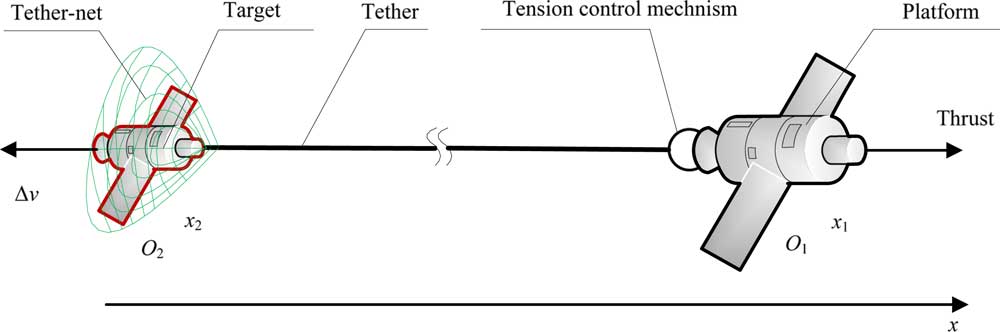
The STC after the target is captured is shown in Fig. 1. The system is composed of the platform, the tension control mechanism, and the tether. To investigate the relative motion of the platform and target, several assumptions are made as follows:
(1) Only the in-plane motion of the STC is considered and the out-of-plane motion is not taken into account.
(2) Attitude motion of the spacecraft is neglected, which means that the platform and the target are considered to be point masses.
(3) The tether is thought to be massless, taut, and straight at all times, and the thrust force F is along the direction of the tether.
(4) Only the deployed length of the tether has strain while the wound tether is assumed to be strain free.
(5) The gravity term is neglected.
(6) There are no other external forces affecting the system such as atmospheric drag, solar light pressure, or lunisolar perturbation.

Figure 1 The STC after the target is captured.
A fixed inertial frame is chosen so that the x-direction is directed from the mass center of the target O 2 to the mass center of the platform O 1 and the origin is in the initial position of the mass center of the target. Let m 1 and x 1 be the mass and the position co-ordinate in the x-direction of the platform, respectively, and m 2 and x 2 be the mass and the position co-ordinate in the x-direction of the target, respectively. R is the radius of the drum in the tension control mechanism, J is the moment of inertia of the drum, L 0 is the total length of the tether, and ξ is the length of the tether wound on the drum; thus, the deployed length of the tether is L 0−ξ. F T is the tether tension force, δ is the elastic deformation of the tether, φ is the rolling angle of the tether, and ω l is the angular velocity of the drum. The following equations are obtained from Newton’s law of motion:
 $$\left\{ \matrix{ m_{1} \ddot{x}_{1} {\equals}F{\minus}F_{T} \hfill \cr m_{2} \ddot{x}_{2} {\equals}F_{T} \hfill \cr} \right$$
Dynamic model of the tether is complex with a time-variant asymmetric hysteresis effect, and it is only stretchable but not compressible. It is supposed that the tether tension is a time-variant function of the elastic deformation and its derivative. As a result, the following expression is obtained:
 $$\left\{ \matrix{ F_{T} {\equals}f\left( {{\rdelta },\dot {\rdelta }},t} \right),{\rdelta }\,\gt\,0 \hfill \cr F_{T} {\equals}0,\quad \hskip 9pt \quad {\rdelta }\leq 0{\rm } \hfill \cr} \right$$
The tension control mechanism is driven by a servo motor and a redactor. The terminal voltage of the armature winding, terminal resistance, terminal inductance, mechanical palstance, and torque constant of the motor are denoted by U, r a , L a , ω e (rad/s), and K e , respectively. Let i and η be the reduction ratio and the efficiency of the redactor, respectively. The dynamic equations of the tension control mechanism are
 $$\left\{ \matrix{ J{\dot{\romega }}_{l} {\equals}{\minus}RF_{{Tl}} {\plus}{\reta }iK_{e} I_{a} {\minus}{\rtau }_{c} {\minus}b{ \romega }_{l} \hfill \cr L_{a} \dot{I}_{a} {\equals}U{\minus}iK_{e} {\romega }_{l} {\minus}r_{a} I_{a} \hfill \cr} \right$$
where F Tl is the tension of the tether leaving the drum, τ c is the Coulomb friction torque imposed on the drum, and b is the viscous friction coefficient. In fact, the tension between the tether leaving the drum and the tether out of the tension control mechanism is different due to the friction applied by the guide rollers in the tension control mechanism, which is denoted by f c . The direction of f c is contrary to the direction of relative motion or relative motion trend. We obtain
 $$F_{{Tl}} {\equals}F_{T} {\plus}f_{c} $$
The relation for the position of the mass center of the platform and target is given by
 $$x_{1} {\minus}x_{2} {\equals}L_{0} {\minus}{\rxi }{\plus}{\rdelta }$$
where ξ=φR. If δ≥0, δ denotes the elastic deformation of the tether, and if δ<0, δ denotes the length of slack in the tether out of the tension control mechanism.
By taking the time derivatives on both sides of Equation (5), we get
 $${\ddot{\rdelta }}{\equals}\ddot{x}_{1} {\minus}\ddot{x}_{2} {\plus}R{\ddot {\rvarphi }}$$
The dynamic model of the STC is established using Equations (1), (3), and (6), and recast into the following state-space form:
 $$\left\{ \matrix{ m_{1} \ddot{x}_{1} {\equals}F{\minus}F_{T} \hfill \cr {\ddot{\rdelta }}{\equals}{\ddot{\rvarphi }}R{\plus}{1 \over {m_{1} }}F{\minus}{{m_{1} {\plus}m_{2} } \over {m_{1} m_{2} }}F_{T} \hfill \cr J{\ddot{\rvarphi }}{\equals}{\minus}b{\dot{\rvarphi }}{\plus}{\reta }iK_{e} I_{a} {\minus}\rtau _{c} {\minus}RF_{T} {\minus}Rf_{c} \hfill \cr L_{a} \dot{I}_{a} {\equals}{\minus}iK_{e} {\dot{\rvarphi }}{\minus}r_{a} I_{a} {\plus}U \hfill \cr} \right$$
where F T is given by Equation(2), and the control system takes the voltage U and thrust F as inputs. Kevlar fiber is always chosen as the material for the tether because of its good mechanical properties. While the Kevlar tether presents strong nonlinear dynamic properties such as viscoelasticity and plastic deformation( Reference Wortmann and Schulz 22 ), it will demonstrate variable stiffness and damping when the tether is too long( Reference Jerry and Larry 23 ).
3.0 LINEARISATION OF THE DYNAMIC MODEL
A simplified incompressible link model is applied to describe the characteristics of tether elasticity and vibration, taking the structural damping of the tether into consideration. The Kelvin model is always used to express the constitutive relation of viscoelastic material, so we obtain
 $$\left\{ \matrix{ F_{t} {\equals}k{\rdelta }{\plus}c{\dot{\rdelta }},{\rdelta }\,\gt\,0 \hfill \cr F_{t} {\equals}0, \hfill {\rdelta }\leq 0 \cr} \right.{\rm }$$
where k and c denote the stiffness and damping coefficients, respectively. In general, the values of the stiffness and damping coefficients are inversely proportional to tether length( Reference Sebastian, Unnikrishnan and Narayanan 24 – Reference Ni, Chen, Ko and Cao 26 ), that is
 $$k{\equals}{{EA} \over {L_{0} {\minus}\rvarphi R}}\,,c{\equals}\rsigma k$$
$$$$
$$k{\equals}{{EA} \over {L_{0} {\minus}\rvarphi R}}\,,c{\equals}\rsigma k$$
$$$$
where E denotes the elastic modulus, A is the tether’s cross-section, and σ is the damping parameter. To simplify the analysis, we suppose that the values of k and c are fixed considering that the change in tether length is relatively small during the anti-impact operation. It can be seen that the friction terms τ c and Rf c are not related to state variables and inputs. We define the following new parameters as
 $$i_{a} {\equals}I_{a} {\minus}{{{\rtau }_{c} {\minus}Rf_{c} } \over {{\reta }iK_{e} }}\,,\quad U_{s} {\equals}U{\minus}{{r_{a} ({\rtau }_{c} {\minus}Rf_{c} )} \over {{\reta }iK_{e} }}$$
Substituting Equation (8) into Equation (7), we can get the state equations
 $$\left\{ \matrix{ {\dot{\mib x}}{\equals}{\mib Ax}{\plus}{\mib Bu} \hfill \cr {\mib y}{\equals}{\mib Cx} \hfill \cr} \right$$
where
 ${\mib x}{\equals}[{\dot{\rdelta },\dot{\rvarphi },\rdelta },i_{a} ]^{{\rm T}} $
denotes the state vector of the state equations, and
${\mib x}{\equals}[{\dot{\rdelta },\dot{\rvarphi },\rdelta },i_{a} ]^{{\rm T}} $
denotes the state vector of the state equations, and
 $$\eqalignno{ & {\mib A}{\equals}\left[ {\matrix{ {{\minus}c\left( {{{m_{1} {\plus}m_{2} } \over {m_{1} m_{2} }}{\plus}{{R^{2} } \over J}} \right)} & {{\minus}b{R \over J}} & {{\minus}k\left( {{{m_{1} {\plus}m_{2} } \over {m_{1} m_{2} }}{\plus}{{R^{2} } \over J}} \right)} & {{{iK_{e} {\reta }R} \over J}} \cr {{\minus}{{cR} \over J}} & {{\minus}{b \over J}} & {{\minus}{{kR} \over J}} & {{{iK_{e} {\reta }} \over J}} \cr 1 & 0 & 0 & 0 \cr 0 & {{\minus}{{iK_{e} } \over {L_{a} }}} & 0 & {{\minus}{{r_{a} } \over {L_{a} }}} \cr } } \right], \cr & {\mib B}{\equals}\left[ {\matrix{ {{1 \over {m_{1} }}} & 0 \cr 0 & 0 \cr 0 & 0 \cr 0 & {{1 \over {L_{a} }}} \cr } } \right],\quad {\mib C}{\equals}\left[ {\matrix{ 1 & {{\minus}R} & 0 & 0 \cr c & 0 & k & 0 \cr } } \right],\quad {\mib u}{\equals}\left[ {\matrix{ F \cr {U_{s} } \cr } } \right],\quad {\mib y}{\equals}\left[ {\matrix{ {\dot{x}_{1} {\minus}\dot{x}_{2} } \cr {F_{T} } \cr } } \right] $$
The open loop transfer function of the STC system is of the form:
 $${\mib W}(s){\equals}{\mib C}(s{\mib I}{\minus}{\mib A})^{{{\minus}1}} {\mib B}$$
where the W (s) is a 2×2 matrix with full rank. A feedforward compensator can be serially connected to the system input and, in this way, the transfer function will be a diagonal rational matrix and the system will be decoupled.
The controllability matrix of the system is
 $${\mib M}{\equals}({\mib B},{\mib AB},{\mib A}^{{\bf 2}} {\mib B},{\mib A}^{{\bf 3}} {\mib B})$$
where rank M is 4 and equal to the dimension of the state vector x . Thus, we can conclude that the system is controllable.
The observability matrix of the system is
 $${\mib N}{\equals}({\mib C}\hskip-.1pt{\hbox;}\,{\mib CA}\hskip-1pt{\hbox;}\,{\mib CA}^{2} \hskip-.5pt{\hbox;}\,{\mib CA}^{3} )$$
where rank N is 4, which means that the system is observable.
4.0 DOUBLE CLOSED-LOOP TENSION CONTROL STRATEGY FOR ANTI-IMPACT
The control objective of the STC is to let the platform and target move at the same velocity by controlling the tether tension. In this way, the platform and target will form a stable combination, and then the target will be towed to deorbit peacefully. A double closed-loop tension-control strategy is designed as shown in Fig. 2 according to the characteristics of the STC model. With the control target of Δv=0, we set the velocity difference demand at Δv ref=0, and then from Equation (1), we obtain
 $$\Delta \dot{v}{\equals}{\minus}{{m_{1} {\plus}m_{2} } \over {m_{1} m_{2} }}(F_{T} {\minus}K_{m} F)$$
where K m =m 2/(m 1+m 2) is the compensation coefficient. We then design the tether tension law as
 $$F_{T} {\equals}K_{{Tp}} \Delta v{\plus}K_{m} F$$
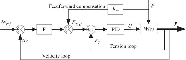
Figure 2 Schematic diagram of double closed-loop tension-control strategy.
So Equation (15) can be rewritten as
 $$\Delta \dot{v}{\equals}{\minus}{{m_{1} {\plus}m_{2} } \over {m_{1} m_{2} }}K_{{Tp}} \Delta v$$
It can be seen that the velocity difference Δv will be exponentially decayed, and the decay rate depends on the gain in the external loop K Tp . A feedforward compensation is added to the tension control input when there exists a thrust force F in the platform in order to set the equilibrium position at the zero point.
The output of the outer loop of the velocity difference is a tension standard F Tref of the input to the inner loop comparing the tension standard F Tref with the feedback tension F T and the tension error serves as the input of the tension loop PID controller. The output of the PID controller serves as the input voltage U of the motor.
5.0 SIMULATION STUDY
We first study the motion of the STC without control. In order to demonstrate the impact of the tether and the springback of the target, we study the case without the thrust force (that is F=0 N).
We set up the system parameters as shown in Table 1 according to the tension control mechanism and capture mission. The radius of the used Kevlar tether is 1mm with a tensile strain limit of 4.2% and a tensile strength of 2.6GN/m2. The natural length of the tether between the platform and the target is 150m, and the stiffness coefficient is about 324.5N/m, with a fracture tension of about 2041N.
Table 1 System parameters
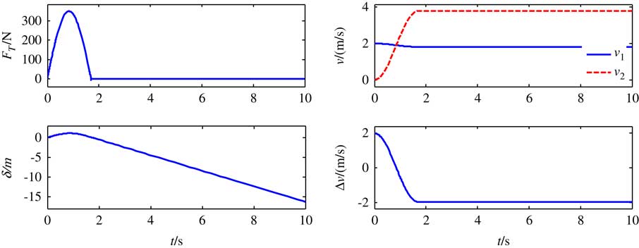
The drum in the tension control mechanism is initially locked by the electromagnetic brake to fix the tether and keep its natural length constant. Suppose that the initial velocity of target v2=−2m/s, the initial velocity of the platform v1=0, and the velocity difference will cause the stretching of the tether. A time history of motion for the two spacecraft and the tether tension is shown in Fig. 3. It can be seen that the platform and the target are separated from each other by a relative velocity of 2m/s at the initial moment, and the tether tension increases to about 350N quickly within a short period of time. The tether will be slack at the instant t=1.7s and the target moves toward the platform with a velocity of 1.7m/s. The target will crash the platform if a maneuvering control is not applied in time.

Figure 3 The simulation results without tension control.
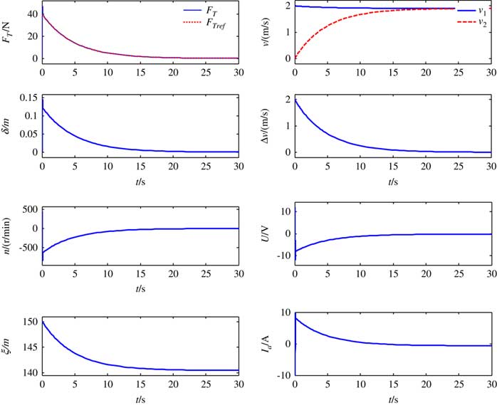
We still suppose that the initial velocity of the target v 2=−2m/s, the initial velocity of the platform v 1=0, and the velocity difference will cause stretching of the tether. The simulation results are shown in Fig. 4 by applying the double closed-loop tension-control strategy with the same parameters from Table 1. The maximum tension is reduced to 60N from 350N, which decreases the impact considerably compared with the simulation results without tension control. The velocity difference decays to 0 rapidly from the initial value of 2m/s by exponential form, which is in accordance with the theoretical analysis in Part 3. The deployment of the tether through the tension control mechanism reduces the elastic deformation of the tether δ and accomplishes the task of avoiding impact. The tether is always taut with nonnegative tension and the length of the deployed tether is about 9m during the entire anti-impact process. This indicates that the double closed-loop tension control is effective and can avoid an impact involving the STC without the thrust force of the platform.
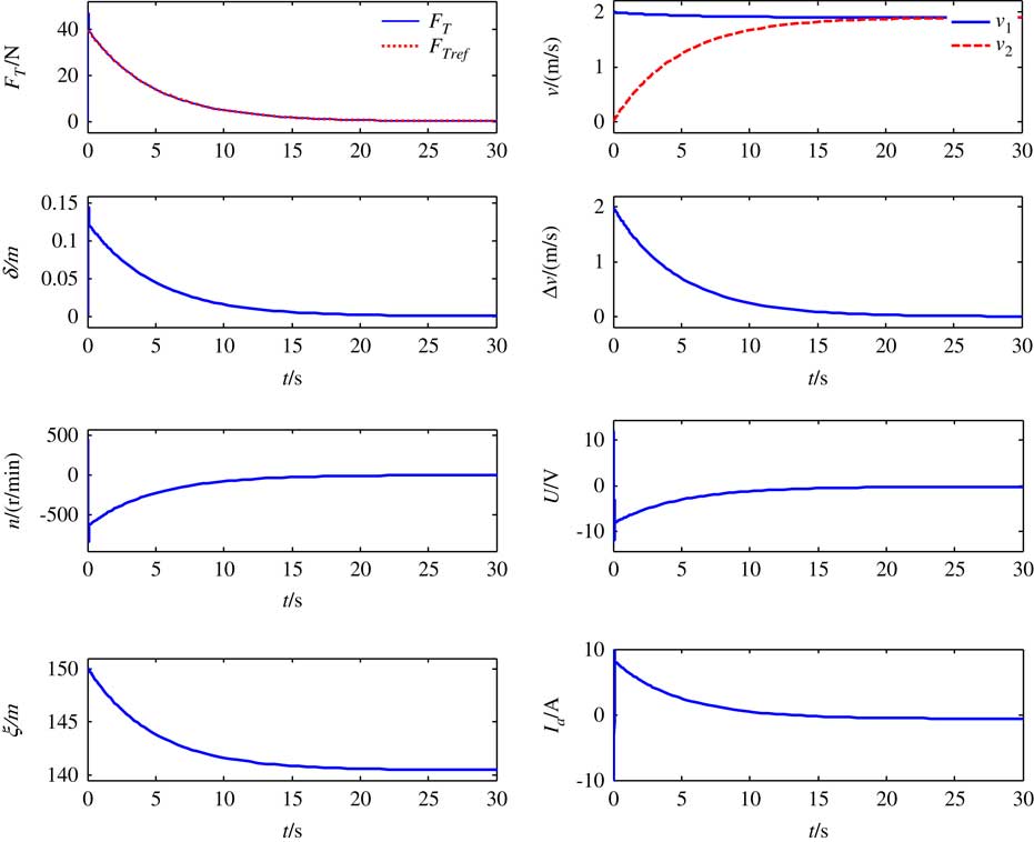
Figure 4 Simulation results for double closed-loop control.
6.0 EXPERIMENTAL STUDY
The ground experiment system (shown in Fig. 5) includes a flat floor, a platform simulator, a target simulator, the tension control mechanism, some visual inspection devices, and the host computer. The target simulator is connected to the platform simulator by a thin tether. The tension control mechanism is fixed on the platform simulator to control the tether tension. The platform simulator and target simulator can float on the surface of the flat floor with the help of planar air bearings. Measurement of each position of the simulators is achieved through the visual inspection devices and the marks pasted on the simulator. In order to improve the elasticity, the nylon tether is used in the ground experiment. The radius of the used nylon tether is 0.15mm with a fracture tension of about 40N.
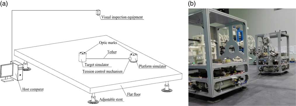
Figure 5 The ground-based flotation platform.
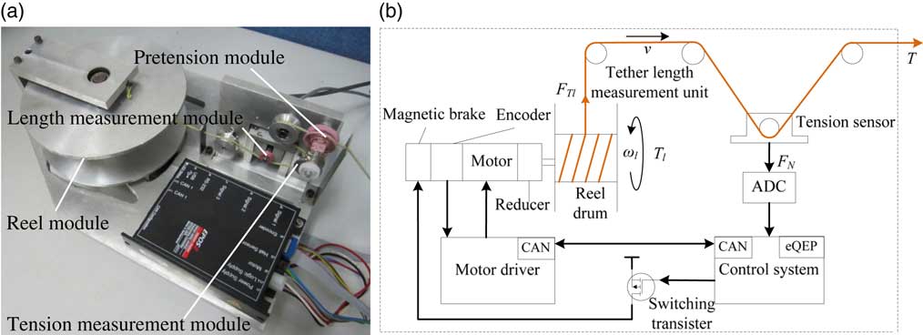
As shown in Fig. 6, the tension control mechanism is constituted of the reel module, the length measurement module, the tension measurement module, and the pretension module. The reel module achieves the deployment and retrieval of tether by the reel motor and reel drum. The pretension module is to keep the tether under a micro-tension. The main goal of the tension control mechanism is how to measure the length and tension of the tether.

Figure 6 Tension control mechanism.
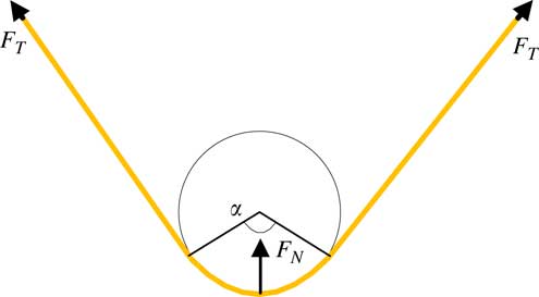
The tether tension cannot be measured directly, because the tether will be rolled on the reel drum continuously. Then an indirect measurement method is adopted, whose measuring principle is shown in Fig.7, the tether is rolled on the roller, and then the sensor detects the normal force F N , and the relationship between the tether tension T and F N can be obtained from force analysis
 $$F_{N} {\equals}2T{\rm sin}\left( {{\ralpha }\,/\,2} \right)$$

Figure 7 Indirect measurement principle of tether tension.
from which we can measure the tether tension T easily.
The measurement of tether length is realized by a quadrature encoder and a linked roller as shown in Fig. 8. The friction between the tether and the roller will rotate the roller, and the encoder will count the rotation rounds of the roller n, then we can get the length of deployment or retrieval tether by the formula
 $$l{\equals}nr$$
where r is the radius of the roller. The rotation direction of the roller can be judged by the phrase difference between the two phrase signals.
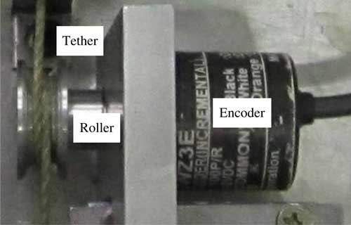
Figure 8 Tether length measurement module.
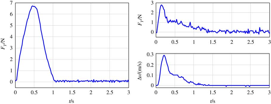
Set the initial velocity of the target v 2=−0.3m/s and the initial velocity of the platform v 1=0. The tension in the tether increases to about 6.8N in 0.5s. The tether will be slack because of the impact and the target is knocked on the platform at last. The experiment results of the double closed-loop tension control strategy are shown in Fig. 9. The platform simulator and target simulators move with the same velocity and the tether tension is reduced to 2.8N. The tether was taut throughout the experiment and the velocity difference decayed to 0 gradually.

Figure 9 The experiment results on the ground-based flotation platform.
The tether is too short used in the ground experiment and the material of tether in ground experiments is nylon which is different with Kevlar tether used in the simulation, because of the ground platform is too small. But we can see clearly that the maximum of tether tension decreases from 6.8N to 2.8N by application of double closed-loop tension control strategy and the two simulators move with the same velocity at last. Although the parameters in the ground experiment are different with the parameters in simulation, but the experiment results validate the effectiveness of the double closed-loop control once again.
7.0 CONCLUSIONS
In this work, first, a electromechanical coupling model of the STC is put forward and the dynamical system is controllable and observable through linearization analysis. Second, a double closed-loop tension-control strategy is proposed with an inner tension loop and a velocity difference outer loop to avoid the impact caused by the initial velocity difference. Third, both the cases without control strategy and with double closed-loop tension-control strategy are simulated. The simulation results without tension control show that a great impact will be brought by the initial velocity difference and the target will crash the platform. The simulation results for double closed-loop control show that the impact can be avoided by deployment of the tether. The platform and the target can finally move with the same velocity and the tether is constantly taut using the double closed-loop control. Finally, the experimental results further validate the effectiveness of the double closed-loop control. In the future, the three-dimensional motion and the nonlinear dynamic property of the tether will be taken into consideration to further improve the control strategy.
ACKNOWLEDGEMENTS
This work was supported in part by the National Natural Science Foundation of China (Grant no. 51475411) and in part by the Zhejiang Provincial Natural Science Foundation of China (Grant no. LQ17E050011).