


NOMENCLATURE
- AATF
-
Aircraft Anechoic Test Facility
- ACETEF
-
Air Combat Environment Test and Evaluation Facility
- ADTRA
-
Advanced Dynamic Transmit Array
- AESA
-
Active Electronically Scanned Array
- AFB
-
Air Force Base
- AFTC
-
(US) Air Force Test Center (formerly AFFTC, Air Force Flight Test Center)
- APG
-
Advanced Pulse Generator
- ARES
-
Advanced Radar Environment Simulator
- ASIL
-
Avionic Systems Integration Laboratory
- ATF
-
Anechoic Test Facility
- A2PATS
-
Advanced Architecture Phase, Amplitude and Time Simulator
- BAF
-
Benefield Anechoic Facility
- CAT
-
(ISTF) category
- CEESIM
-
Combat EM Environment Simulator
- CNI
-
Communications, Navigation and Identification
- COMINT, COMSEC
-
Communications Intelligence, Communications Security
- C3
-
Command, Control and Communications
- DAC
-
Defensive Aids Computer
- DAS, DASS
-
Defensive Aids System, Sub-System
- DDS
-
Direct Digital Synthesis
- DIN
-
Deutsches Institut für Normung (German institute for standardisation)
- DIRCM
-
Directed IR Countermeasures
- DoD
-
(US) Department of Defense
- EA
-
Electronic Attack
- ECIT
-
Electronic Combat Integrated Test
- ECM
-
Electronic Counter-measures
- ELINT
-
Electronic Intelligence
- EM, EMC, EME, EMI
-
Electromagnetic, EM Compatibility, EM Environment, EM Interference
- EMCON
-
Emissions Control
- EP
-
Electronic Protection
- E-Scan
-
Electronically Scanned
- ESM
-
Electronic (or EW) Support Measures
- ESD
-
Electro-Static Discharge
- EUROCAE ED
-
European Organisation for Civil Aviation Electronics Document
- EW, EWTF
-
Electronic Warfare, EW Test Facility
- E3
-
EM Environmental Effects
- GbE
-
Giga-byte Ethernet
- GPS
-
Global Positioning System
- HIRF
-
High-Intensity RF
- HITL
-
Hardware In The Loop
- IBST
-
Integrated Battlespace Simulation and Test department
- IFF
-
Identification Friend or Foe
- IOC
-
Initial Operational Clearance
- I/Q
-
In-Phase/Quadrature
- IR
-
Infra-Red
- IRIG-B
-
Inter-Range Instrumentation Group – format B (time code standard)
- ISTF
-
Installed System Test Facility
- ITEA
-
Integrated Test, Evaluation and Acceptance
- JEM
-
Jet Engine Modulation
- J-PRIMES
-
Joint Pre-Flight Integration of Munitions And Electronic Systems
- LAC
-
Large Anechoic Chamber
- LSS
-
Lightning Strike Simulator
- M&S
-
Modelling and Simulation
- MF
-
Measurement Facility
- MIL STD
-
Military Standard
- MJC
-
Multi-Jammer Characterisation
- NATO
-
North Atlantic Treaty Organization
- NAVAIR
-
(US) Naval Air Systems Command
- NEWEG
-
Next-generation EW Environment Generator
- NGJ
-
Next-Generation Jammer
- NRL
-
(US) Naval Research Laboratory
- O&M
-
Operation and Maintenance
- OAR
-
Open Air Range
- QZ
-
Quiet Zone
- RAF
-
Royal Air Force
- RAM
-
Radar Absorbent Material
- RCS
-
Radar Cross Section
- RF
-
Radio/Radar Frequency
- RISS
-
Real-Time IR/Electro-Optic Scene Simulator
- RSJ
-
Rolled Steel Joist
- RSS
-
Radar Signal Simulator
- RWR
-
Radar Warning Receiver
- SAE
-
Society of Automotive Engineers
- SatCom
-
Satellite Communications
- SCADA
-
Supervisory Control and Data Acquisition
- SE
-
Synthetic Environment(s)
- SIGINT
-
Signals Intelligence
- SIL
-
System Integration Laboratory
- SMS
-
Signal Measurement System
- SSLNA
-
Solid State Low Noise Amplifier
- SUT
-
System Under Test
- T&E
-
Test and Evaluation
- TW
-
Test Wing
- TWTA
-
Travelling Wave Tube Amplifier
- UAS, UAV
-
Unmanned Air System, Unmanned Air Vehicle
- US, USA, USAF
-
United States, US of America, US Air Force
- UV
-
Ultra-Violet
- WARM
-
War Reserve Mode(s)
1.0 INTRODUCTION
This paper considers capabilities, benefits and limitations of aircraft-sized Radio/Radar Frequency (RF) anechoic chambers for Test and Evaluation (T&E) of Electronic Warfare (EW), Radar and other Electromagnetic (EM) aspects of air and ground platforms. It has been produced now, against a backdrop of continuing downward pressure on worldwide defence budgets, to support increased chambers’ use to help improve affordability of platforms’ and systems’ development and in-service support, reduce risk and minimise timescales. This originally EW-based chamber type has successfully supported cost-effective development and in-service support of Western EW systems on fixed and rotary wing aircraft for over 40 years and is likely to do so for the foreseeable future. Each aircraft-sized anechoic chamber (hereafter referred to as ‘chamber’), a selection of which is depicted in Fig. 1, resides within a test facility parent building.

Figure 1. Selection of chambers.
This paper describes this type of chamber, provides a development history and indicates benefits vs. flight trials, where this term means developmental flight test and operational evaluation. The T&E process and facilities, as used for EW system development and clearance into service, are explained and the contribution of such chambers to that process identified. Capabilities and uses are then elaborated, with emphasis on key infrastructure and instrumentation, and the expansion of use for T&E in other EM areas is described. Operation and maintenance are discussed, as are T&E limitations, based on experiential knowledge from international use. The paper concludes with a view of trends and challenges.
EW systems are key enablers of platform survivability in conflict situations and combat operations. Whilst this chamber type's original use was for EW, including T&E of Defensive Aids Systems (DAS) and Defensive Aids Sub-Systems (DASS), and Electronic Attack (EA) platforms, this has expanded to cover T&E across much of the EM spectrum. A key feature of chambers is the ability to conduct T&E of nationally sensitive equipment and systems, fully installed on platforms, in absolute secrecy.
There are currently few known chambers worldwide (Fig. 2), with two in the UK.

Figure 2. Locations of known aircraft-sized anechoic chambers. (© 2016 BAE SYSTEMS. All rights reserved).
This paper is unclassified, and much information herein has been publicly released by its originating agency or is already in the public domain. Some important caveats apply:
-
• It covers only chambers where public release information exists, so it may not be exhaustive, and specifically excludes chambers dedicated to Radar Cross Section (RCS) measurement or to EM Compatibility/Interference (EMC/EMI) testing. It is not intended as a comparison of those identified. Rather, it indicates the art of the possible, focusing on the range of T&E capabilities and uses of chambers as examples of what is nowadays achievable. It does not guarantee any particular chamber facility has a specific sub-capability. For this, one needs to contact the chamber's parent facility agency directly, and Reference Welch and PywellRef. 1 provides contact details for many chambers herein.
-
• Images and references to chambers, T&E facilities and resources are provided as examples only.
-
• Directed Energy Weapons, defined in North Atlantic Treaty Organization (NATO) as a sub-set of EW, are, with the exception of Directed Infra-Red (IR) Countermeasures (DIRCM), excluded.
-
• EW systems and consequently T&E equipment operate in the same technical parameter space, since all operate generally with the same multi-spectral threat environment. No requirement or numeric in the paper is intended to be associated with any specific System Under Test (SUT), platform or programme. Throughout this paper, the term SUT means the Test Article or Device Under Test, each of which can be an equipment, a sub-system, a system or an entire platform.
-
• Emitter databases, essential to EW systems and T&E, are not discussed because they are nationally sensitive.
The authors have been involved with BAE Systems’ EW Test Facility (EWTF), with its aircraft-sized chamber, since its 1981 conception. Their start point for this paper was chambers that were originally designed for testing platform-installed EW systems. The authors will show how chambers’ utility has expanded over the years such that, subject to test mission requirements and affordability, they can now be used for the evaluation of most EM aspects of military and civilian platforms, their systems and equipment.
2.0 MODERN DASS AND EW T&E PROCESS
This section introduces a typical modern, integrated DASS and describes the T&E process applied to assure acceptability and fitness for purpose.
2.1 Typical modern DAS -Typhoon
For those unfamiliar with EW and DAS, a typical modern DAS is that on the Typhoon aircraft. It comprises the ‘PRAETORIAN’ DASS (Fig. 3) as fitted to the UK Typhoon and provided by the EuroDASS consortium, the Defensive Aids Computer (DAC), Chaff and Flare Dispensers, and a Laser Warner. The Praetorian DASS provides Electronic Support, Radar Countermeasures and Missile Approach Warning capabilities, which are integrated with the rest of the DASS and avionic system via the DAC. Most DASS components are housed in the Wing Tip Pods with the Avionics Bay housing the DAC, Processor, Techniques Generator, RF Source and Power Supply.

Figure 3. Typhoon's Praetorian defensive aids sub-system. (© Leonardo MW Ltd 2016 All rights reserved).
2.2 T&E process used for EW
This section describes the generic T&E process for platforms and systems, as tailored for EW, as depicted in Fig. 4. This process, which is well understood and is documented in the NATO EW T&E handbook(Reference Welch and Pywell1), is a series of events leading to optimised systems and accredited readiness for combat.

Figure 4. T&E process as used for EW systems. (Edited from Welch and Pywell(Reference Welch and Pywell1)).
For technical, timescale, risk and affordability reasons it is important to use the right facility or combination of facilities for required evidence gathering to prove platform and system acceptability. National processes, like the UK Ministry of Defence's Integrated Test, Evaluation and Acceptance (ITEA) process(2), enable determination of optimal facilities’ balance for a given platform or system. For the design, development and customer acceptance of new platforms the whole range of T&E facilities, which are described in Section 3.0, are generally utilised. A particular consideration is test design, results accuracy and repeatability(Reference Welch and Pywell1). Chambers as described herein are able to offer scientifically repeatable test results in a controlled EM environment. Test set-ups and procedures can be reliably reproduced, removing a significant variability in testing and reducing results’ uncertainty.
EW is a good example where, historically, most T&E was conducted by the repetitious ‘Fly-Fix-Fly’ method, which is now unaffordable – in cost and time. Introduction of very capable RF threat simulatorsFootnote 1 and signal measurement systems, as will be discussed in Section 8.0, has enabled a major shift from flight trials to chamber and laboratory facilities. Whilst this chamber type has most often been used to satisfy T&E process elements for manned air platforms, Unmanned Air Systems (UASs), which includes Unmanned Air Vehicles (UAVs), have also been tested. T&E challenges across the EM spectrum are stressing for manned platforms and some, e.g. RF interoperability, are more complex on UASs. It is considered that UAS programmes would particularly benefit from chamber facility capabilities and developments described herein.
3.0 HIERARCHY OF T&E FACILITIES
This section describes T&E facilities, with emphasis on Installed System Test Facilities (ISTFs), which these chambers are, and indicates where they fit into the T&E process.
3.1 T&E capabilities and facilities
Many T&E capabilities are needed to support platforms’ and systems’ design, development and customer acceptance. A T&E capability can be defined as a:
‘combination of facilities, equipment, people, skills and methods, which enable the demonstration, measurement and analysis of the performance of a system and the assessment of the results’(3).
Internationally understood facilities' types are depicted in Fig. 5 and described here(Reference Welch and Pywell1):
-
• Modelling and Simulation (M&S) and Synthetic Environments (SEs) are used to demonstrate system performance for aspects too complex or expensive to verify by test, estimate error bounds where repeatability is difficult, and target practical T&E required.
-
• Measurement Facilities (MFs) are used to establish the character of a system or technology, such as installed antenna patterns, and includes Open Air Test Sites.
-
• System Integration Laboratories (SILs) are facilities designed to test the performance and compatibility of components, sub-systems and systems when integrated with other systems or functions. They are used to evaluate individual hardware and software interactions and, at times, involve the entire weapon system avionics suite. The SIL type includes Avionics Integration and Sub-System Laboratories.
-
• Hardware In The Loop (HITL) facilities provide a controlled and secure environment to test EW techniques and hardware, and other sensors against real or simulated threat systems. These include such laboratories in the UK's Joint EW Operational Support Centre, RAF Waddington.
-
• Open Air Ranges (OARs) are used to support EW systems’ evaluation, in particular of those that cannot be realistically ground-tested, for example: chaff, flares and towed/expendable/air-launched decoys. They are also used for development and optimisation of tactics and countermeasures.
-
• Installed System Test Facilities (ISTFs) are covered in the next sub-section.

Figure 5. T&E capability types. (Except HTIL & OAR images, © 2016 BAE SYSTEMS. All rights reserved).
3.2 Installed system test facilities
ISTFs are anechoic or shielded facilities and fall generally into the Table 1 CATegories (CATs), although some are multi-CAT. ISTFs usually comprise chambers in which free-space RF radiation is used to stimulate the SUT, and its responses are measured and evaluated in total EM security. Their purpose is primarily to evaluate integrated avionics systems in installed configurations; to test specific functions of complete, full-scale weapon systems; and to verify specific, platform-level performance against specification. Systems include radar; IR; Communications, Navigation and Identification (CNI); EW systems; and integrated controls and displays.
Table 1 Capability description by ISTF CATegory

These developed from the Electronic Combat Integrated Test (ECIT) Facilities’ CATs, where there was also CAT IV(4), but this no longer exists, having been subsumed into CAT III. CAT I ISTFs would have all possible sub-capabilities required to evaluate platforms and their systems. No such all-encompassing facility existed in 1992, and its cost was estimated at $400 M(5). Table 1 of Ref. 5 interestingly maps capability (Yes/No/Limited) vs. CAT number (I-IV) for the capability headings: Man-in-the-loop; Many-on-many; Spectrum coverage; Red/Blue/Neutrals; Closed loop; Open loop; C3 simulation; Theatre force level; Many-on-one; and Full-scale vehicle.
Chambers herein are CAT II, with varying levels of CATs I and III sub-capabilities. Government ISTFs, e.g. Benefield Anechoic Facility (BAF) and Advanced Systems Integration Laboratory Large Anechoic Chamber (ASIL LAC), tend to have more sub-capabilities than Industry ones. The EWTF is a good example of an Industry ISTF. Operational for 19 years, it was designed for EW testing of Eurofighter Typhoon and similar-sized aircraft, and is Class IV laser light-tight. Figure 6 shows typical ISTF testing.

Figure 6. Testing Typhoon wing-tip pods and Apache in typical ISTFs.
4.0 HISTORY OF THIS TYPE OF CHAMBER
This section provides a brief history of chambers for EW and related testing. This type of chamber was initially developed in the United States in the late 1960s to help reduce EW systems’ development costs, timescales and risks. This type has been, for some time, helping meet challenges facing individual nations worldwide and, likewise, alliances (cf. Reference Pywell and Midgley-DaviesRef. 6). EW systems were previously developed by SIL and MF tests, with extensive OAR flight trials. Table 2 shows the limited number of such chambers worldwide, with Initial Operational Clearance (IOC) year. Whilst not exhaustive, as others may exist, these are chambers for which information exists in the public domain.
Table 2 History of aircraft-sized RF anechoic chambers

The last two, although designed primarily for EMC/EMI testing, are included as they cover EW-useful microwave/millimetre frequency ranges, have aircraft hoists and are understood to have or have plans for adjunct EW T&E capabilities. Whilst there are three main classes of anechoic chamber: rectangular, compact range and shaped (including tapered)(Reference Hemming7), all chambers covered herein are rectangular. The reasons for this traditional shape are many and include chamber size and versatility; technical applications and trade-offs; and structural strength to cater for hoists. Such trade-offs include required frequency range versus size of Radar Absorbent Material (RAM) and chamber corner reflection control. QinetiQ's ATF, whilst described as ellipsoidal (believed to result from use of a pre-existing parent building), it is also considered to be a rectangular class chamber.
As can be expected, there are and have been few chamber infrastructure suppliers. By way of example, the below is a non-exhaustive list of past and present suppliers:
-
• Chambers: ATEC Industries; Cuming Lehman Chambers; E&C Anechoic Chambers NV; ETS-Lindgren (formerly EMC Test Systems, itself formerly EMCO, Rantec and Ray Proof, augmented by acquisition of Lindgren RF Enclosures); Howell Corp.; Howland Company; Microwave Vision Group (formerly Rainford EMC Systems, AEMI, ORBIT/FR and SATIMO); Siepel.
-
• Main entry door, where not manufactured by chamber supplier: Fleming Steel.
-
• RAM: Cuming Microwave Corporation; Laird NV (formerly Emerson & Cuming Microwave Products); Panashield; Sahajanand Laser Technology; Seipel; Soliani.
It is worth noting that the first chamber, the Grumman AATF (Fig. 7), went out of service in 1994. When commissioned in 1968, it was the largest such facility and was subsequently used as a model for later chambers of this type(8). Interestingly, this AATF's RAM cone material was horse hair mat impregnated with lossy carbon mixture, enabling a low-frequency performance (60–500 MHz) that was superior to the original ACETEF AATF and BAF, and this also permitted higher radiated power in this AATF than those chambers at that time(Reference Olver9).

Figure 7. EA-6B ‘Prowler’ in Grumman AATF. (Photo – Grumman History & Aeronautical Research Center).
Given their longevity, it is unsurprising that ‘technology refresh’ upgrades to chamber infrastructure and instrumentation are required. These are driven by obsolescence and end-of-life considerations, in addition to sub-capability introduction and/or expansion to meet emerging and changing test mission requirements (cf. Reference OlverRef. 9). Whilst upgrades driven only by mission requirements occur in line with SUT programme timelines, major upgrades tend to occur every 10–15 years. For cost-effectiveness and to constrain loss of availability for testing, the timing of such upgrades is generally harmonised with as many test mission-required changes as practicable. Two examples are the:
-
• BAF's ECIT upgrade programme, which introduced many sub-capabilities the BAF now has. Unfortunately, upgrades of any size inevitably equate to temporary loss of some or total chamber capability. The BAF, for example, was closed for most of FY2003, 14 years post-IOC, for ECIT capability installation, reducing the number of achieved test days that year by 75% compared to (FY2000-2 +FY2004-6) test days’ average(Reference Thirtle10).
-
• EWTF Refresh, described in Reference Pywell and Midgley-DaviesRef. 6 and which was operational in 2010, 12 years’ post-IOC. Key elements were: new threat simulator and signal measurement and time synchronisation systems; replacement chamber RF amplifiers; refurbished and upgraded turntable; new, multi-platform hoist equipment; improved fire detection and suppression; and updated intra-facility communications.
5.0 SIZES OF RF ANECHOIC CHAMBERS
This section describes chamber volume categorisation and indicates the wide range of aircraft-sized chambers’ floor area vs. height. These chambers come in many shapes and sizes, dependent upon their test missions. Whilst there is no international standard on sizes, the US Department of Defense (DoD) has used ‘Small’, ‘Mid-Size’ and ‘Large to Extra-large’ categories(11), as shown in Table 3.
Table 3 Sizes of RF anechoic chambers

All chambers in Table 2 fall in the latter category, and Fig. 8 is an example of a ‘Mid-Size’ one, showing Typhoon Electronic Support Measures/Countermeasures (ESM-ECM) full system testing. Figure 9 demonstrates chamber size variety, indicating shield (i.e., excluding RAM) height vs. floor area. Whilst many are single fighter–sized, two are particularly large and can cater for two or more aircraft under test: the ASIL LAC(12) and the world's largest chamber, the BAF(Reference Sabat13–15).

Figure 8. ESM-ECM full system testing in ‘Mid-Size’ chamber. (© Leonardo MW Ltd 2016 All rights reserved).

Figure 9. Chamber name vs. floor area vs. height.
Figure 10 indicates the BAF's size: 80.5 m (264 feet) long, 76.2 m (250 feet) wide and 21.3 m (70 feet) high. Its ceiling slopes to 20.7 m (68 feet) at the walls to prevent water collection due to accidental discharge of the hangar fire protection system(Reference Hemming7).

Figure 10. Tornado in BAF. (Photo – 412th TW, Benefield Anechoic Facility, Edwards AFB).
6.0 BENEFITS VS. FLIGHT TRIALS
This section identifies chamber testing's primary benefits (Fig. 11) and highlights key ones.

Figure 11. Chamber testing benefits vs. flight trials.
Affordability: Defence Ministries require reduced platforms’ whole life costs. The T&E community continues to develop process and facilities, enabling an optimum mix of capabilities for cost-effective T&E of platforms and systems(Reference Pywell and Midgley-Davies6). Late problem discovery poses cost and timescale risk to programmes. Figure 12, based on a consideration of data sources including Reference SteckleinRefs 16 and Reference Dawson17, indicates an almost exponential cost increase with problem discovery phase. Earlier discovery reduces on-aircraft ground and flight trials required to fully qualify systems, and reduces fuel cost and carbon footprint.

Figure 12. Relative cost to fix problems vs. programme phase.
Pre-combat survivability confidence: Often, chamber testing is the first time full platforms are exposed to threat environments and thus survivability confidence is increased. Subject to chamber capability, tactics and RF counter-measures’ can be optimised, and training and mission rehearsal provided. EW and Radar War Reserve Modes (WARM) can be exercised in privacy, unlike on OARs.
Test repeatability: Enhances ability to repeat, isolate and quickly resolve developmental and operational problems via highly controlled test conditions.
Weather-proof: These chambers have a particular benefit to EW, EM and non-EM testing traditionally conducted outdoors – they are weather-proof. Their use can de-risk timescales of a given platform, system or equipment test programme for this reason alone.
7.0 KEY INFRASTRUCTURE
This section covers the key elements of chamber infrastructure and includes some design considerations that need to be addressed when provisioning such chamber facilities.
7.1 Chamber construction
The chamber's inside needs to have as high an RF isolation from the outside world as possible for security and test interference prevention, especially for nationally sensitive test missions. This is achieved by constructing a metal-walled enclosure, commonly called the RF shield. Practically achievable typical shield isolation for this type of chamber is 70 dB @ 30 MHz rising to ≥100 dB from 0.5 to 40 GHz. Higher isolation is possible, but not without cost increase and trade-offs of other aspects of a chamber's capability and utility.
This chamber type is usually required to be TEMPEST-grade, where TEMPEST is a National Security and NATO certification referring to spying on information systems through leaking emanations, including unintentional radio or electrical signals, sounds and vibrations(Reference Jiemin18). To achieve this, shield construction is broadly common across chambers, with a Rolled Steel Joist (RSJ) skeleton supporting fully welded galvanised steel sheets(Reference Hemming7). This skeleton is critical, to enable a large, clear intra-chamber volume and to support hoist systems, where fitted. Joists’ size and cost rises substantially as chamber volume increases. Galvanised steel sheets are used, typically 1.2 m × 2.4 m × 3 mm, and they are fully peripherally welded to the skeleton (e.g., Fig. 13). Large chambers have kilometres of welds and certified welders are required, as problems can be expensive to rectify as well as compromising the chamber's integrity. All welded seams need to be tested, which takes significant time and presents stretching challenges, e.g. positioning of test equipment.

Figure 13. Example of welded panelling and RSJs. (© 2016 BAE SYSTEMS. All rights reserved).
Typical chamber structures appear in Reference HemmingRefs 7 and 19. Access panels, human and equipment access doors, and air conditioning penetrations are expensive to install and maintain to satisfy very high shielding performance requirements. All moveable/re-moveable panels and doors are usually fitted with RF gaskets, whose type is dependent on their size and function.
Main chamber doors present significant challenges, requiring particular attention to maintain TEMPEST-grade shielding. Modern systems use a triple inflatable bladder system, similar to large bicycle wheel inner tubes, pressing metal (e.g., beryllium copper) RF gaskets onto metal mating surfaces (Fig. 14).

Figure 14. Chamber main door construction and RF gasketing. (© 2016 Fleming Steel).
7.2 Radar absorbent material and quiet zones
This section provides an introduction for those unfamiliar with RAM and Quiet Zones (QZ). These are well-understood topics and a number of references exist( Reference Hemming 7 , Reference Rodriguez 20 , Reference Saville 21 ).
7.2.1 RAM types and characteristics
RAM is designed and shaped to absorb rather than reflect incident RF energy. Its purpose is to minimise chamber interior surfaces’ impact on tests conducted in the QZ. It is used in chambers to ensure that the SUT experiences a RF environment closely approximating the in-flight case. RAM types and sizes are tailored to required test missions. A single configuration fully covering all missions does not exist, e.g. RAM types and shapes for EW testing are not optimised for RCS measurements. Three principal types are used in chambers: pyramidal, wedge and convoluted (‘egg box’) and each's use is dependent on test type(Reference Hemming7). EW-based chambers predominantly use pyramidal RAM, with heights typically 0.46–1.83 m, and with typical reflectivity of −20 dB @ 100 MHz, improving to −50 dB @ 40 GHz. Figure 15 indicates typical RAM types, including ferrite absorber tiles which can provide 30–1,000 MHz attenuation of plane waves.

Figure 15. Examples of RAM types. (© 2016 Sahajanand Laser Technology Ltd).
Commonly used RAM is typically made of fire-proofed, solid urethane foam impregnated with conductive carbon black, e.g. ECCOSORB VHP-NRL. An alternate, carbon-less type, Frankosorb, is nano-thinfilm metallised plastic bonded to hollow pyramidal foam supports. Modern hybrid RAM, with 30 MHz to 40 GHz operating range, is good for EMC/EMI and EW testing, but not all hybrid technologies have as good reflectivity as conventional pyramidal RAM at microwave and millimetre wave frequencies.
RAM is fixed to walls and ceilings using one or more of: contact adhesive; rail and clip systems; and Velcro. To allow SUT installation and re-configuration, floor RAM can be fixed or removable and can be fitted to removable pallets for optimal operational flexibility. Different types of RAM are used in critical areas to maintain design performance. Floor RAM can be covered or boxed (see Fig. 7) to provide human walkways and enable instrumentation transit to/from the SUT.
Chamber RAM's typical power handling capability is 1.5–8 kWm–2. Horse-hair RAM (cf. Section 4.0) had higher than standard capability but is no longer used. Capability can be increased, for example, for high-power radar and High-Intensity RF (HIRF) EMI testing, by:
-
• replacing original RAM with higher-power RAM, as 2014-implemented in the BAF(Reference Fabara22), see the pale-blue-backed American flag (3.1 kWm−2 RAM) in Fig. 16.
-
• forced air cooling, usually for only a small section of the chamber. Whilst 100 kWm–2 and higher could theoretically be achieved with commercially available RAM with sufficiently high air flow, practically realisable capabilities are understood to be much lower.
-
• use of re-locatable high-power RAM boards, with/without forced air cooling.

Figure 16. B-1B ‘Lancer’ on BAF turntable. (Photo – 412th TW, Benefield Anechoic Facility, Edwards AFB).
If specified power handling levels are exceeded, carbon-based RAM can smoulder or set on fire, and some types could then give off toxic gases. RAM and chamber manufacturers have to comply with the requirements of Naval Research Laboratory (NRL) 8093, which was introduced after three 1973–1976 serious chamber fires in the United States. Modern RAM uses reduced toxicity materials and has intrinsic flame retardant properties to assure compliance with these standards. One type, Frankosorb, is worthy of note as, since it is not carbon-based, it is non-combustible (DIN 4102, fire-class A2).
Further fire and safety resilience exists in chambers via temperature monitoring systems that scan for hotspots and shut RF transmission systems down if safe operating temperatures are exceeded. RAM particulate shedding, a problem of early RAM types, is much less so nowadays via improved materials and over-painting. Shedding with age and handling, especially around regularly used chamber doors, remains an issue. Techniques such as positive air pressure are used to constrain particulates within the chamber's RF shield, for subsequent clean-up and removal. RAM can have a service life ≫15 years, but this may be shortened when installed on chamber walls and ceiling due to glue degradation with age and torsional effects for wall-mounted RAM.
7.2.2 Quiet zones
QZs (a.k.a. Test Regions) are where a chamber has minimal effect on RF tests conducted therein. They provide an approximation to free space that is acceptable for required tests. QZ size is generally determined by the largest SUT. It is typically turntable size and usually geometrically centred within the chamber. QZ size and shape is also a function of chamber size and shape, frequency, and RAM type and reflectivity. Typical QZ shapes are cylindrical, spherical and rectangular. No internationally agreed definition of QZ exists but principal elements pertaining to this chamber type are understood:
-
• Signals emanating from the SUT need to be attenuated such that any chamber-interior-reflected signals cannot be detected by the SUT's receivers. Single and multi-bounce reflections of signals transmitted from the QZ, by chamber walls/floor/ceiling and fixtures, are controlled to a design level, often the SUT's RF receivers’ sensitivity.
-
• Chamber instrumentation RF transmission signals (cf. Section 8.3) need to arrive at the SUT's surface with sufficient signal uniformity, in amplitude and phase, to adequately approximate to far-field radiation for the tests to be conducted (cf. Section 10.3.2).
Usefully sized QZs can have reflection-isolation as good as 70–100 dB, as a function of frequency, for the largest chambers. Whilst dependent on chamber size, RAM configurations and frequency, QZ field purity and performance can be as good as 0.5 dB amplitude taper, 0.2 dB amplitude ripple and <5° phase variation. QZ performance is confirmed during chamber build and checked periodically thereafter as required, for example on changes to RAM type/size/configuration and if required for a specific SUT's test programme. This performance is measured by QZ probing, where a probe antenna is moved through the QZ volume to determine the level of inbound extraneous signals. Reference Sirles, Mantovani, Howland and HartRef. 23 is a useful source of information on chamber electromagnetic characterisation, including an improved QZ probing technique using spherical near-field imaging techniques.
7.3 Turntables
About half the chambers listed have turntables and most are centrally located. The others have hardened central floor areas capable of taking platforms of the size they were designed for. The BAF turntable (see Fig. 16) is located centrally in one chamber axis but slightly off-centre in the other. At least one, the EWTF (Fig. 17) has a two-position turntable which is easily re-locatable via sub-turntable air bearings. The most often used position is central. The second, 4.7 m toward the door, provides extra distance to the main threat site wall when conducting high-power radar tests.

Figure 17. EWTF's turntable at secondary test zone position. (© 2016 BAE SYSTEMS. All rights reserved).
Table 4 indicates the turntables’ cardinal parameters. Most chambers with turntables have a shielded basement or subterranean chamber or laboratory. Aircraft services, e.g. power, cooling and hydraulics are typically routed via this area and up through the floor to the SUT. All services need to be RAM-shrouded, with the hole in the floor being the last item to be RAM-shrouded. Any test cables requiring entry through the RF shield are either passed through RF bulkhead connectors or inserted using the waveguide beyond cut-off technique.
Table 4 Turntable cardinal parameters

7.4 Hoists
Hoists are required to lift the SUT to the QZ centre, nominally half chamber height, where many tests are conducted. Typical hoists are shown in Fig. 1. Some are fixed centrally over the turntable, if there is one. Others can move the SUT floor-to-ceiling along the chamber's central axis, either for testing purposes or for SUT ingress/egress without having to move floor RAM. The lifting capability range for chambers in this paper is 23–36 tonnes per hoist.
The BAF has two fixed location hoists, each capable of lifting a fighter-sized platform. Hoisted platforms can be rotated in azimuth independently or in conjunction with turntable rotation at up to 3°s–1, with the hoisted aircraft generally strap-linked to the turntable. These accurate lifting and positioning systems allow angle of arrival and antenna pattern tests. Aircraft are lifted using a platform-specific harness or generic lifting frame (Fig. 18(a)). The ASIL LAC (Fig. 18(b)) can lift a Boeing 707–sized aircraft with its two hoists linked.

To mitigate reflections, hoist materials (crane block, lifting frames, straps and cables) are either non-conductive, e.g. Kevlar and fibre-reinforced polymer, or RAM covered as necessary for the specific tests to be conducted.
8.0 KEY INSTRUMENTATION
This section covers the suite of key instrumentation used in chambers for EW T&E and addresses considerations that drive capability and cost.
8.1 RF threat simulators
RF threat simulators (a.k.a. RF emitter generators) are a key but expensive element of chambers. They generate a mimic of the multi-emitter EM environment that platforms’ RF sensors would see operationally. That environment comprises threat, own, friendly and neutral military and civilian emitters, as depicted in Fig. 19. Threat emitters consist of command and control, early warning, tracking and guidance radio/radar transmitters associated with land-/sea-/air-based weapon systems, such as Surface-to-Air and Air-to-Air Missiles. These systems are operated by all sides – ‘Red’ emitters are associated with hostile platforms, ‘Blue’ emitters with own-side and friendly platforms, and ‘Grey’ emitters are neutrals. RF emitters of most EW interest are split into two classes: Continuous Wave and Pulsed, which have multiple RF characteristics, including frequency, pulse width, pulse repetition interval and modulation type (amplitude, frequency, phase).

Figure 19. The electromagnetic battlespace. (Photo – 412th TW, Benefield Anechoic Facility, Edwards AFB).
Threat simulators are necessary to reduce time and expense in developing, integrating, evaluating and supporting EW receiver and processor systems. Originally covering the traditional 2–18 GHz EW band, they now support T&E requirements for EW, Information Operations and other RF-based sensor systems across the modern-day most EW-important band of 500 MHz to 40 GHz; and Communications, Navigation and Identification bands down to 20 MHz. They generate scenarios via computer-controlled RF signal sources (‘channels’ or ‘source channels’), whose outputs are merged to represent the aggregate signal that would exist at a given point in space and time – the SUT's location. Further information on RF threat simulators can be found in Reference PywellRefs 24, Reference Pywell25 and Reference Pywell and Midgley-Davies6.
Without high-fidelity representations of threat system radars, EW system performance can be different in combat to that seen in laboratory and chamber trials, posing a risk of mission, aircraft and aircrew loss. By simulating emitters’ RF characteristics and transmit antenna motions for a number of land, sea and airborne platforms in a scenario, the simulator can create a simulation of what an aircraft's sensors would see as it flew through this EM battlespace. A key simulator capability is to produce real-time dense RF scenarios, an ongoing computing and digital circuitry challenge.
RF source types (Fig. 20) are taken into account during cost-benefit trade-offs when specifying threat simulators. High-speed synthesisers are the highest-quality mainstream source but are more expensive than the commonest sources hitherto available. Many simulators thus tend to have fewer of these synthesisers, which have traditionally been reserved for highest-quality emitter simulation. Common high-end simulators include the Combat Electromagnetic Environment SIMulator (CEESIM)(26) and the Radar Signal Simulator (RSS) 8000(27) (Fig. 21), and the Advanced Multiple Environment Simulator. These high-end simulators are capable, at the digital level, of simulating over 4,000 emitters and over 1,000 platforms, each with one or more emitters on them. RF scenario density and complexity is constrained by RF source quantity. To adequately simulate combat-realistic, high-density RF scenarios, simulators need many RF sources, which, unfortunately, is a significant cost driver. For typical maximum pulse density scenarios for chamber testing, simulators need to be able to generate ca.260 emitters and a pulse density of >1 M pulses per second(14). Using one RF source per emitter, the ideal solution, is unaffordable, so high-speed multiplexing is used to enable scenarios to be produced with acceptable pulse drop-out rates using much lower numbers of sources.

Figure 20. RF signal source types.

Figure 21. Example high-end RF threat simulators.
8.2 Chamber RF distribution systems
Some chambers have dedicated EW test instrumentation, whilst others share such instrumentation with an EW SIL or HITL. Sharing is usually affordability driven, as this instrumentation is multi-£M expensive. There is a need to route RF and digital control signals around the facility, and Fig. 22(a) indicates typical routing. As will be discussed in Section 8.3, RF signals generated by threat simulators are routed via RF amplifiers to transmit antennas within the chamber (e.g., Fig. 22(b)), whilst RF signal measurements taken in the chamber are routed back to signal measurement and analysis systems. Copper RF cables are usually used for chambers using fixed antenna sites, whilst those using mobile antenna carts (see Section 8.3) use fibre-optic signals to control threat simulator RF channels remotely located on the carts to drive amplifiers and antennas.

Figure 22. (a) Example chamber RF distribution system. (b) Chamber-corner threat site. (© 2016 BAE SYSTEMS. All rights reserved).
8.3 Amplifiers and transmit/receive antennas
To generate the EM battlespace, simulator outputs are routed via amplifiers to transmit antennas, typically mounted at fixed threat sites (see Fig. 22(b)), or on mobile carts. Amplifier types are usually Travelling Wave Tube Amplifiers (TWTAs) and Solid State Low Noise Amplifiers (SSLNAs). A carts’ example is the BAF's 20 original units, some of which are shown in Fig. 23. These have 7–35 feet, height-adjustable antenna masts with frequency sub-banded transmit antennas atop of each.

Figure 23. Amplifier and antenna configurations. (Photo – 412th TW, Benefield Anechoic Facility, Edwards AFB).
Typical amplifier powers are 10–250 W, although much higher powers are used for certain tests. To provide perfect simulation, or ‘emulation’, of this battlespace for testing EW systems, a chamber would need a high number of amplifiers, many with powers ≫1 kW, something which is generally unaffordable. Such capability is mostly unnecessary, because exercising EW receivers over their full range of received signal strengths, to simulate initial detection of threats (at maximum range) through to minimum engagement range (in extremis the over-fly case), is generally conducted during un-installed receiver testing on SILs at the receiver equipment supplier and platform systems integrator. Once again, the ITEA process informs the type, scope and mix of T&E facilities to be used to achieve customer acceptance and readiness for combat. Each facility thus has an appropriate and affordable combination of amplifier quantity and powers, with optimisation methods to cater for their required test missions. Methods include being able to quickly re-configure the location of amplifiers and their associated antennas. For example, the EWTF has sufficient transmit antennas for up to 10 amplifiers at each of its fixed threat sites and available amplifiers can be quickly re-located between sites. Another example is the BAF's carts, each of which can be rapidly moved anywhere in the chamber. Receive antennas, used for measuring SUT-emitted signals and the intra-chamber RF environment, can be free-standing and/or co-located with transmit antennas (see Fig. 22(b)).
8.4 Signal measurement systems
It is life-and-death critical for EW warning systems to quickly and un-ambiguously identify threat systems and for the platform's DAS to engage threats with appropriate and timely countermeasures. This ‘system response time’ is in the order of a few seconds to a few minutes. To adequately evaluate the correct functioning and performance of EW systems, it is thus necessary to use high-performance and high-speed RF signal gathering to verify threat simulator RF outputs and analyse ECM techniques (jamming responses).
Various signal measurement equipment types are used, e.g.:
-
• stand-alone spectrum and pulse domain analysers.
-
• high-end systems like Signal Measurement System (SMS), shown in Fig. 24, as used at the EWTF.
-
• the BAF's Automatic Measurement System.
-
• Electronic Intelligence (ELINT) receivers.

Figure 24. Signal measurement system and example analysis displays. (SMS Photo © 2016 BAE SYSTEMS. All rights reserved). (Displays © 2011 Northrop Grumman - Amherst Systems).
Some systems can also be used to fully characterise the RF performance of real threat system radars, or at least their transmitters’ RF outputs, in the privacy of a chamber. Besides their primary role of measuring, recording and analysing ECM waveforms and timing, an equally important role of these systems is verification and validation of threat emitter waveforms generated by RF threat simulators. This topic is discussed further in Section 5 of Reference PywellRef. 24.
8.5 Test control and synchronisation of T&E systems
Chamber facilities require comprehensive test control and real-time synchronisation capability to enable adequate platforms’ T&E. This is especially so for testing modern military aircraft, with their multi-spectral sensor systems, sophisticated sensor fusion capabilities, integrated weapon systems and increasingly intelligent avionic systems( Reference Sabat 13 , Reference Andrews 28 , Reference Jones 29 ). The primary functions of this capability are:
-
• Master test, measurement and data recording system controller.
-
• Simulators’ synchronisation, including data networks’ and timing synchronisation.
-
• Provision of necessary navigation system and other simulations to ensure the platform's diagnostic systems cannot tell that it is being ground- rather than flight-tested. Without this latter feature it is not possible to adequately test modern platforms, with their advanced self-awareness capabilities.
-
• Data management, including test scenarios’ development, data acquisition and analysis.
Of particular importance is that all test facility time stamps are based on the same clock. Some facilities have a stand-alone time synchronisation system, whilst others have this embedded within the test systems, e.g. in the EWTF's SMS. Often a chamber's time synchronisation system feeds multiple digital networks that connect various T&E equipment: high-speed ones for RF-level events, usually via memory-mapped real-time data networks, and slower ones for SUT bus-level events. The most demanding synchronisation requirement is usually between threat simulators and signal measurement equipment, typically ±5 ns. Although test control and synchronisation capabilities tend to be bespoke, Fig. 25 depicts a commercially available Synchronisation and Control System(30) and indicates how multiple simulators can be controlled to ensure the SUT is presented with a correlated, real-time set of multi-spectral sensor inputs driven by a common scenario.

Figure 25. Facility synchronisation control system. (© 2016 Northrop Grumman - Amherst Systems).
9.0 USES IN OTHER AREAS OF ELECTROMAGNETICS
This section highlights other areas of EM T&E that can nowadays be supported by chambers and considers some of particular interest. Discussion of some areas is not possible in this unclassified paper. For further information, direct contact with chamber agencies is required.
9.1 Chamber T&E capability expansion
Potential was recognised from the outset for wider chambers’ use in equipment, systems and platform T&E across the EM spectrum. This utility has greatly expanded since then and now extends across the product life cycle, from R&D and prototyping; through design and development; and on to production clearance and subsequent support to in-service operations and platform upgrades. Technology, toolsets’, materials’ and T&E techniques’ developments have improved their actual and potential uses. Their flexible nature has led to use for many more activities than the type's original remit for EW T&E. Figure 26 indicates the current art of the possible. Other chamber uses include EMC testing of non-military platforms, e.g. automobiles, and for non-testing activities (e.g., films and media). Excellent examples are shooting of scenes from the films Armageddon and Terminator II in the BAF. Individual T&E sub-capabilities and equipment are nowadays often specified as mobile or, at least, easily transportable, to improve their utilisation and T&E location flexibility. This enhances T&E equipment cost-effectiveness and offers opportunities for further utility of chambers that cannot justify sole ownership of a specific T&E sub-capability or equipment.
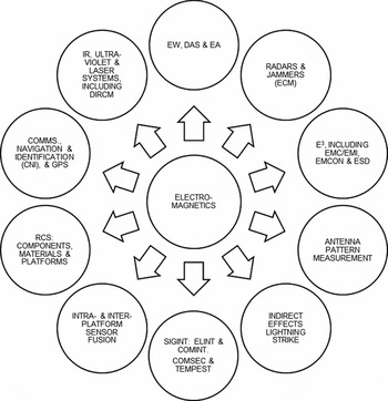
Figure 26. Chambers’ use for other areas of electromagnetics.
9.2 Radars and jammers
9.2.1 T&E of radars and jammers
The importance of airborne radars and RF ECM (on-/off-board self-protection and EA jammers) to military aircraft mission success and platform and aircrew survivability cannot be over-stated. Consequently, these systems’ capabilities, especially Electronic Protection (EP) features and WARM, and any limitations thereof are closely guarded secrets by nations. This particular national sensitivity extends to their T&E and thus anechoic chambers of various sizes, for example those at Leonardo (Edinburgh and Luton) and those described herein, are used to support radar and jammer development. Aircraft-sized anechoic chambers are especially useful when these systems are integrated into the host platform, where their intrinsically high EM security permits platform- and avionic system-level testing that one does not wish non-friendlies to be aware of. Within this unclassified paper, it is not possible to discuss many interesting aspects of radar and jammer T&E. However, the authors intend that the following provides an indication of capabilities available to assist and the challenges applicable to this specialised and secretive test mission.
9.2.2 Radar target generators and ECM simulators
SUT radars can be stimulated via use of radar target generators, for example Chameleon II (Fig. 27) and Advanced Radar Environment Simulator (ARES) (Fig. 28)(14). These generators, produced by EW Simulation Technology Ltd.(27) and RF Simulation Systems Inc.(31), respectively, enable the radar to track and identify targets using tactically appropriate waveforms and to exercise systems’ WARM, in total privacy if conducted in a chamber. Additionally, jammer simulators and/or real jammers can be introduced to the chamber to test the Radar's EP features. Likewise, ESM receivers can be stimulated using threat simulator(s) and then the SUT's jamming response can be captured via a threat response measurement system for analysis post-test (cf. Section 8.4). This provides a true end-to-end test capability from detection to identification to response. Once again, the ability to perform this activity in privacy is paramount to maintaining a fighting edge over adversaries.

Figure 27. Chameleon II radar target and ECM simulator. (© Ultra Electronics Ltd. 2014).

Figure 28. Testing using ARES. (Figure – 412th TW, Benefield Anechoic Facility, Edwards AFB).
Using radar target generators also enables testing other radar performance aspects, e.g.:
-
• cooperative (Identification Friend or Foe (IFF)) and non-cooperative identification (e.g., Jet Engine Modulation (JEM)).
-
• detection and tracking of targets with different RCS, and of other difficult targets, such as low and slow moving objects, e.g. helicopters, which need to be distinguished from the surface clutter in a radar's look-down search.
9.2.3 AESA radars and phased array jammers – a T&E challenge
Radars and jammers are generically already sophisticated and are becoming even more so, posing significant challenges to the T&E community. The current EW T&E paradigm is challenged by upcoming Active Electronically Scanned Array (AESA, a.k.a. Electronically-Scanned (‘E-Scan’)) radars, some with EA capability, and phased-array ECM, e.g. Next-Generation Jammer for the EA-18G ‘Growler’. More complex waveforms can be generated and controlled; multiple, independent beams can be generated, pointed and controlled; and improved beam pointing accuracy can be obtained.
Significant challenges exist and are being addressed by the T&E community(32 , Reference Solt and Monserrate33):
-
• Provision of adequate three-dimensional simulation of land/sea/airborne AESA radars and phased array jammers, using threat simulators, for laboratory/chamber/OAR use.
-
• In-chamber generation of simulations of these types of emitters using novel transmission systems, e.g. Advanced Dynamic Transmit Array (ADTRA) initiative (see Section 10.3.3).
-
• In-chamber measurement of SUT AESA and phased array jammer beams, particularly for characterisation of multiple, inter-dependent jammers that simultaneously jam different targets in different frequency sub-bands at different locations in space. NAVAIR's novel Multi-Jammer Characterization (MJC) system at the ASIL, for example, was introduced under Block A of the Next-Generation EW Environment (NEWEG) programme(Reference Solt and Monserrate33).
Chambers already provide the capability to conduct radar and DASS testing in privacy (Fig. 29) and enable development of novel and innovative SUT functionality. With appropriate development of threat simulators, chamber RF transmission systems and multi-beam measurement and analysis capability, it is thought that chambers could adequately cover much of the T&E envelope for modern AESA-based radar and jammer systems.

Figure 29. Typhoon E-Scan radar and DASS tests in EWTF. (© 2016 BAE SYSTEMS. All rights reserved).
9.3 Electromagnetic compatibility and interference
Chambers are intrinsically useful in whole platform EMC/EMI testing due to their high RF shielding. EMC means that a device is compatible with its operational EM environment, i.e. no interference is caused to it by that environment, and that it does not emit levels of EM energy that cause EMI in other devices operating in that environment. EMC/EMI is part of E3 (US terminology), a.k.a. EM Hazards. EMI types are conducted emissions, e.g. spikes transferred through cabling to other devices; radiated emissions, e.g. free space transmission into and within avionics bays causing disruption to systems; and Electro-Static Discharge (ESD). Chambers are especially useful:
-
• Radiated Susceptibility test capability (Fig. 30) is limited only by available high-power amplifiers and transmit antennas, and chamber RAM capability. Amplifiers used for HIRF testing are usually in the kW range rather than generally lower powers used for EW T&E.
-
• Measurement of antenna-to-antenna isolation and coupling can also be performed (see Section 9.4) to validate modelling and to optimise antenna siting on the platform in support of acceptable interoperability of on-board RF transmission and receiver systems.
-
• Measuring radiated emissions’ content to inform Emission Control (EMCON) policy.

Figure 30. Example of radiated susceptibility test capability. (Figure – 412th TW, Benefield Anechoic Facility, Edwards AFB).
Figure 31 indicates two typical test types. This utility extends to any ‘leaky’ EM test technique, such as indirect effects lightning strike and High-Level Direct Drive (a.k.a. Direct Current Injection)(34). Constraints imposed by increasingly restrictive free-space RF transmission regulations suggest that chambers may soon be the defined location for much of the EM T&E discussed in this paper, not just for nationally sensitive EW and radar testing, but also more generally for HIRF and other EMC/EMI testing involving such transmissions.

Figure 31. Typical chamber EMI testing – HIRF and microwave ‘spot’. (© 2016 BAE SYSTEMS. All rights reserved).
9.4 Antenna pattern measurement
Antennas are key components of RF transmitter and receiver systems, which in turn are essential to modern military operations. These systems operate across much of the RF spectrum, from radios through to ESM and ECM systems, operating at up to 40 GHz and beyond. Optimising antennas’ performance is thus important, to assure robust interoperability with other land/sea/air platforms and, crucially, to optimise survivability when in harm's way during combat. As part of the systems' optimisation process, it is essential to know un-installed and platform-installed antenna patterns and gains for three main reasons, to:
-
• optimise receiver system performance during the SUT design and development phase.
-
• verify performance for un-installed/installed antennas during development and production phases.
-
• programme threat simulators for post-antenna laboratory EW testing during all phases of the platform life cycle.
Figure 32 shows example results of platform-level antenna polar pattern measurements that are possible in a chamber. The patterns of four Radar Warning Receiver (RWR) antennas can be seen, each providing nominally quadrant coverage around the platform. The interested reader is referred to Reference MacnamaraRef. 35 for further information about antenna placement and installation.

Figure 32. Example measured antenna pattern data. (Figure – 412th TW, Benefield Anechoic Facility, Edwards AFB).
Much system-level performance can be confirmed via M&S, but this necessitates prior acquisition of measured data to validate that M&S(Reference Macnamara35). Data for all these purposes can be gathered via a range of measurement facilities, as shown in Fig. 33.

Figure 33. Antenna pattern measurement facilities. (Except Leonardo images, © 2016 BAE SYSTEMS. All rights reserved).
9.5 Indirect effects lightning strike
Lightning strike poses a threat to military and civilian air platforms. On average, a military aircraft gets struck by lightning twice in its life, so the probability is small. The impact of a lightning strike, however, can be catastrophic:
-
• War-time: whether leading to mission abort or, rarely nowadays, to total aircraft loss.
-
• Peace-time: loss of aircraft potentially causing damage to property and loss of life.
A combination of computer modelling and tests is used to confirm safety of flight for a new or significantly modified aircraft type. For example, the Typhoon aircraft was tested, as shown in Fig. 34, using a platform type-specific return conductor, with over 1,800 sub-threat and eight full-threat strikes. Conducting these tests in the EWTF's anechoic chamber meant zero RF interference was caused to Airfield Services, Air Traffic Control and the local community, and there were no weather interruptions to testing.

Figure 34. Typhoon undergoing lightning strike testing in EWTF. (© 2016 BAE SYSTEMS. All rights reserved).
Lightning Strike Simulators (LSS) used by agencies around the world vary in capability. Fibre-optic control and monitoring is utilised – there are no physical electrical connections to the LSS's high-voltage/current generator. BAE Systems’ LSS, as an example, could reproduce the initial return stroke and the subsequent strokes in accordance with the test waveforms of Ref. 36. It could test objects with realistic direct-strike lightning pulses up to a maximum peak current of 200 kA for a single stroke, 100 kA for a subsequent stroke, and several hundred Amperes of continuing current for hundreds of milliseconds. Its output waveform was comparable to natural lightning in pulse rise and fall times, peak current and continuing current amplitude and duration.
10.0 CHAMBER SERVICES, OPERATION AND T&E LIMITATIONS
This section describes main services required to support chamber testing; operational aspects, including provisioning, calibration and maintenance; and limitations and mitigations.
10.1 Chamber services
Whilst this topic could be an entire publication in its own right, only the main services are listed below and two of particular interest discussed. For further information, the interested reader can refer to Annex A of Reference Welch and PywellRef. 1, which provides further services information for chambers of this type.
-
• Platform/SUT Support Services, including turntables (Section 7.3) and hoists (Section 7.4).
-
• High-pressure and flow rate hydraulics; forced air and liquid cooling
-
• High-volume air conditioning
-
• High-capacity alternating and direct current power supplies.
-
• Closed-circuit television monitoring/recording – safety surveillance, security and trials.
-
• EMC-hardened monitoring and remote control systems (Fig. 35).
-
• Fibre-optic and secure communications; data acquisition, simulation and recording.
-
• Fire detection and suppression systems (Fig. 35).
-
• Flight-line access: Whilst not a ‘service’ per se, chambers are generally quick and easy access. Most are adjacent to the flight-line or a taxi-way, thus providing fly-in, test, fly-away capability.

Figure 35. Example services: EM-isolated cameras and gaseous fire suppression systems.
Two of the above are worthy of further discussion:
-
• SUTs and facilities, including their test equipment, are extremely expensive, so chamber fire detection and suppression systems are particularly important. Originally, many chambers had water-based suppression systems, but, unfortunately, water causes irreparable damage to most RAM types, necessitating costly and time-consuming RAM replacement. In recent times, there has been a move towards using gaseous suppression systems in chambers. These are a significant improvement over water-based systems, as they cause no harm to humans, have minimal effects on the SUT and test equipment, and require little post-fire clean-up effort.
-
• Data acquisition, simulation and recording: Besides RF threat simulation, signal measurement and time synchronisation equipment already described, chambers have data acquisition, simulation and recording capabilities.
10.2 Provisioning, operation and maintenance
Figure 36 indicates important aspects when planning and operating chambers. Whilst a full discussion is out of this paper's scope, a number of un-prioritised points of note are made.

Figure 36. Main operational aspects of chamber facilities.
Chamber facilities’ initial provisioning and major upgrade programmes have typical lead times (start specification to ready-for-use) of 3–6 years, based on experience and Reference OlverRef. 9, and a service life (a.k.a. Useful Life) measured in decades. Beyond initial specification and facility provisioning, much effort is expended (see Section 4.0) on obsolescence management, technology refresh and life extension activities; as well as test mission-driven capability upgrades. A particular challenge is deciding when best to replace aged and/or obsolete instrumentation and infrastructure, especially high-value items such as threat simulators. Whilst there is no single figure for complex instrumentation, it is believed to be 10–15 years, with increased risk of degrading performance in the latter years. Infrastructure refurbishment or replacement periodicity is less easy to define, with some items lasting much longer than originally specified.
A key learning point from experience is that, wherever possible and affordable, as much future-proofing should be designed in at the outset. Reasonably foreseeable future upgrades usually cost more if done as an in-service modification than at initial build. As important is the disruption caused to T&E operations when availability of key infrastructure and/or instrumentation is lost to enable upgrade implementation (cf. Section 4.0). This is an ongoing problem for chamber operators and their customers alike.
Staffing models vary between chamber agencies and between platforms’ test and support teams. The total number of staff required to cover a platform trial varies with test mission complexity and trial phase, from pre-trial activities through post-test chamber remediation. The peak total number of staff per shift is typically 11–16 for the most complex trial type covered in this paper. An insight into chamber facility staffing can be gleaned from Reference PearsonRef. 37.
Access control and security management is paramount. Most chambers have multiple controllable and isolatable zones, to cater for high-classification trials and special projects. Such features as automated card key and key-code access provide a layered approach.
Chamber and instrumentation maintenance and calibration are significant, time-consuming tasks, with shielding/RAM performance (including regular inspection and preventative maintenance of chamber doors and access panels), TEMPEST certification and threat simulators’ calibration particularly onerous. As a generic indication of the size of these tasks, Table 4.12 ‘BAF FY06 workload by Type’ of Reference ThirtleRef. 10 shows 39% for ‘Calibration’. Chambers are also unavailable for testing during these periods, as exemplified in Section 4.0. Given chamber facility longevity, emphasis is placed on optimising these tasks, especially vs. high T&E workloads; attainment of cost-effective, whole-life support; and ultra-reliability developments for selected facility components. An example of this emphasis is the potential for significantly reduced threat simulator calibration times via adoption of recently introduced Direct Digital Synthesised (DDS) RF sources.
Chambers’ trials planning is, as for those in other T&E facilities, key to efficiency, effectiveness and affordability. Pre-trial questionnaires assist greatly in this regard and bring clarity to the complex, multi-stakeholder activities required to assure trials’ success. Such documents cover booking and security arrangements; considerations for T&E of a given SUT; chamber and instrumentation pre-trial preparations; day-to-day operational arrangements, including staffing; data recording and analysis requirements; and post-trial reporting. Chamber pre-trial preparation and post-trial remediation to its standard configuration can take appreciable time dependent upon test type and RAM configuration(s) required. For maximum test type flexibility, some chambers have removable floor RAM and this can, if palletised, be removed and replaced relatively quickly using pallet movers (Fig. 37).

Figure 37. Chamber floor RAM pallet and mover. (© 2016 BAE SYSTEMS. All rights reserved).
10.3 T&E limitations and mitigation
This section discusses un-prioritised limitations impacting chambers' use for EW and EM T&E beyond those already mentioned, and identifies some mitigating factors. Other relevant limitations, risks and mitigations are covered elsewhere (e.g., Reference Welch and PywellRef. 1 (Ch. 9) and Reference GilmoreRef. 38).
10.3.1 Chamber sub-capabilities matrix
No known single chamber facility has a fully capable suite of all possible sub-capabilities. Each has a sub-capabilities matrix appropriate to their planned test missions. As mentioned in Section 3.2, government facilities, e.g. BAF and ASIL LAC, have most of the possible sub-capabilities. Industry-owned chambers generally have fewer sub-capabilities by comparison, driven by test mission requirements and affordability. It is worth noting that sub-capabilities that are common across chambers are broadly technically equivalent. Notwithstanding this fact, all such facilities have greater or lesser limitations in at least one area of their capability. Often these limitations do not adversely affect the ability to execute required test missions and in others cases mitigation is available.
In some cases limitations are acceptable, as shortfalls may be adequately covered, see Sections 2 and 3, by other facilities as part of the SUT's ITEA methodology. In other cases, alternate T&E facilities may not be feasible, and engineers then need to consider the viability, impact and acceptability of workarounds, including accepting wider measurement error bounds in return for reduced risk of problems being found later in programmes, including during flight trials.
10.3.2 Far-field (‘Free-space’) constraints
Antenna performance in the reactive (or non-radiating) near-field, radiative (or transition) near-field (Fresnel region) and radiating far-field (Fraunhofer region) is well understood (cf. Reference MacnamaraRefs 35 and Reference Hein39). Whilst not detailed herein, it is an important factor in chamber sizing and specification of transmit and receive instrumentation antennas. A general constraint of this chamber type is that their size cannot fully cater for true far-field testing over the full frequency range of the chamber, for all sizes of SUT and for all test mission types. This would require impractical and unaffordable sizes.
For the in-flight case, the SUT and its installed antennas are generally in the far-field of transmitting antennas of threat/friendly/neutral RF-transmitting antennas on land/sea/air platforms. To adequately simulate this ‘free-space’ transmission case, transmitting antennas in chambers need to be far enough away from the SUT antenna(s) for the test to be valid. This also applies reciprocally, where an SUT's antenna's installed polar pattern is to be measured to verify conformance to specification and to optimise antenna placement.
The far-field distance is considered to be 2D2/λ, where D is the maximum dimension of the antenna, and λ is the wavelength of the radio/radar wave. The value D is highly dependent on the SUT and test to be conducted and can range from the size of a single SUT-installed antenna or chamber instrumentation antenna, to a nose radar antenna, to an ESM antenna array where individual antennas are placed at the extremities of an aircraft. For example, the far-field distance for a 1-m diameter nose radar antenna would be 53 m at 8 GHz rising to 80 m at 12 GHz (the commonly used I/J radar band).
A key feature of far-field testing is that the electromagnetic wave-front should be planar as it impinges on the SUT. In general, a wave approximates to being planar if phase taper across the part of the wave-front impinging on the SUT is <22.5° and if phase variations across that part are sufficiently small. Exactly how much wave-front degradation is tolerable is decided on a test-by-test basis as part of test design, including pre-test accuracy, error budget and pass/fail criteria considerations(Reference Welch and Pywell1 , 2). This constraint is often not a real problem, for example RWR Direction Finding, where pragmatism and appropriate error budgets can suffice to satisfy test missions. As necessary, near-field to far-field measurements’ transformation techniques and, if required, compact antenna ranges can be used to overcome or mitigate this chambers’ constraint for specific test missions.
10.3.3 Fidelity of threat emitter and multi-emitter scenario simulation
Section 8.1 describes RF threat simulators and explains their position as arguably the most important instrumentation in chambers used for EW T&E. Capabilities and limitations of these simulators are considered to be adequately described in Reference Welch and PywellRefs 1 and Reference Pywell24, and in Chapters 4 and 5 of Reference PywellRef. 25. Primary limitations affecting EW T&E are given here and Section 11 indicates mitigating developments.
Single-emitter simulation fidelity, for laboratory and chamber testing: Producing simulations that are identical to real-world threats they are supposed to represent remains an elusive goal. This is exacerbated by threat radar developments and ever-increasing capabilities of ‘digital’ EW receiver systems towards unambiguous identification of threat emitters in next-to-zero time. Primary features impacting a threat simulator's capability in this area are type of RF source used and ability to fine-grain shape pulses in amplitude/frequency/phase domains.
Multi-emitter scenario simulation fidelity for laboratory and chamber testing: This is covered in Reference PywellRef. 25. The primary feature impacting a simulator's capability in this area is its maximum pulse density capability, traditionally its number of RF channels. 1.5–3.5 Million Pulses Per Second (MPPS) is considered adequate for most HITL/SIL testing of modern EW systems. Many chamber tests can be adequately executed with ca.1.5 MPPS, but the highest density and thus most realistic scenarios can only be achieved with much higher MPPS(Reference Pywell25). For example, the BAF has a 24 channel simulator, capable of generating up to 7.35 MPPS in laboratory (‘direct injection’) mode and up to 2.0 MPPS in chamber mode(14). It is being FY2016-upgraded to 36 channels(14) by addition of six extra transmission carts, each with two 2–18 GHz APG channels(40).
This complies with the US Director of Operational T&E's recommendation to upgrade (US) government anechoic chambers with adequate numbers of signal generators for realistic threat density(Reference Gilmore41) and supports the Mission Rehearsal goal discussed later in this sub-section. Figure 38, further to a prior survey (cf. Reference PywellRef. 25, Fig. 5.2), underscores the above, indicating threat simulator quantities vs. MPPS sub-banding.

Figure 38. Pulse density capability.
Additional constraints for chamber testing, involving amplifiers and antennas: Single and multi-emitter scenarios’ fidelity that can be simulated in chambers is additionally constrained. Quantities, types and positioning of transmit antennas, and RF amplifier quantities and powers are constraints. A full suite of antennas and appropriately powerful amplifiers is unaffordable. Much useful work, however, can be done using antenna/amplifier combinations nowadays present in chambers. In addition, initiatives such as the USAF's ADTRA seek to address current limitations on providing adequate simulations of high power and electronically scanned, multi-beam emitters in chambers(42 , 43).
An optimal antenna configuration for EW T&E, if affordable, could be a mix of aforementioned fixed sites and mobile carts, utilising ADTRAs (once available) and MJC, with one chamber sector covered by a higher-resolution antenna's array similar to NRL's Central Target Simulator chamber (Fig. 39). This NRL HITL facility has a missile seeker (the SUT) mounted on a 3-axis flight motion simulator 75 feet from a wall-mounted spherical array of 225 dual-polarised transmit antennas.

Figure 39. High-resolution array of transmit antennas. (Photo – US Naval Research Laboratory, Tactical EW Division).
10.3.4 Chamber size, turntable and hoists
The scope of some test types is limited by the physical size of chamber, aside from the maximum size of SUT the chamber can cater for. Physical constraints and practical considerations also mean that turntables and hoists cannot replicate many aspects of aircraft in flight, in particular flight dynamics. However, the combination of turntables, hoists, modern threat simulators and plentiful and well-located RF threat sites have proven adequate for most test missions.
10.3.5 Chamber RAM performance for T&E below 1 GHz
As indicated in Section 7.2, chamber lining RAM is outset-tailored to required test missions. RAM for chambers that were designed only for radar frequency EW T&E have a useful lower operating frequency of 0.4–1 GHz, noting that the now-closed Grumman AATF had an anechoic range of 60 MHz to 1 GHz via use of ca. 2 m, horse-hair pyramidal RAM. Attenuation and reflectivity performance generally degrades <1 GHz for these chambers and this can prevent or be problematic for conducting other EM T&E types, e.g. EMI and communications systems’ performance.
This useful frequency range can be extended for these chambers, down toward 30 MHz, but this requires one or a combination of special additional configurations of intra-chamber RAM, backing existing RAM cones with ferrite tiles, and replacing existing RAM with newer, hybrid RAM. These options are logistically awkward and not inexpensive, but they are a precursor to maximising pan-EM T&E utility. It is worth noting the two most recent chambers in Table 2 were designed to optimise pan-EM T&E capability and, via use of multiple anechoic materials, have operating ranges of 30 MHz to ≥18 GHz.
10.3.6 Mission rehearsal – the most stretching test mission
To maximise mission success probability, it is necessary to rehearse operational procedures, including tactics and countermeasures to threats. Various flight and other simulators are used to cover much of the rehearsal envelope, but these cannot fully replicate real-world operations without using real sensor systems and platforms and providing their sensors with extensive multi-spectral stimulation.
Full rehearsal is thus currently only possible via flight trials on OARs, albeit scope-limited by available threat types and quantities, where difficult-to-simulate real-world effects such as specular and diffuse reflections from terrain, vegetation, sea, other air platforms and land-/sea-based reflectors are present. Adequate simulation of these features is required to enable threat simulators to mimic real-world effects such as multiple ground reflections in the region of the threat system's radar(s).
The last decade has seen significant developments in key instrumentation, e.g. Table 5 (Reference Pywell25), and computing power increases continue to be a significant enabler. For example, threat simulator calculation of relative host-to-threat geometry was previously constrained to 1–50 Hz update rates, causing stepped outputs for fast moving platforms and high angular rates. Rates of 100–1,000 Hz are now possible, and the ideal, un-constrained real-time geometry on pulse, appears a realisable goal. These developments have increasingly enabled laboratories and chambers to be used to cover more of the mission rehearsal envelope(Reference Pywell25), albeit not yet to the multi-emitter RF scenario fidelity that could be classed as emulation of a particular mission in a specific geographic location and in given seasonal weather conditions.
Table 5 Improvements in threat simulators’ key components and cardinal functions

11.0 TRENDS AND CHALLENGES
This section identifies trend drivers and highlights interesting capability developments, some also applicable to SILs and HITLs. Some are already operational at one or more chambers herein and others are in development. Some will likely enable much of the non-flight dynamics aspects of the mission rehearsal envelope to be conducted using a combination of SILs and chambers. Remaining challenges to optimal use of this chamber type are indicated.
11.1 Trend drivers
As justified by its required test missions and business model, chamber facilities usually have plans or aspirations to enhance their T&E capabilities. Apart from test mission requirements, development trends tend to be driven by three cardinal requirements, the need to:
-
• adequately stimulate and measure responses of ever more complex, multi-spectral and integrated sensor systems as fitted to or being developed as upgrades for manned air platforms and UAS.
-
• move as much T&E from expensive and difficult to repeat flight trials towards adequately validated M&S and SE, via this type of chamber and SILs – to reduce cost, timescales and risk.
-
• significantly drive down costs of development, production and in-service support costs for military platforms – the over-arching and worldwide affordability challenge.
11.2 Improved RF threat and scenario simulation fidelity
Prior limitations (see Section 10.3) are well recognised, as is the trend of increasing EW and radar receiver system performance. This continues to drive the need for improved RF threat and scenario simulation fidelity (Fig. 40). Initiatives such as the DoD-wide, 2011-initiated NEWEG programme(44–47) are seeking to address them, to close the correlation gap between ground-based testing, flight trials and operational use. NEWEG activities continue and are delivering enhancements into ISTFs, for example, in ASIL and within BAF CEESIM upgrade Phases 1–3 and integration studies( 40 , 43 , 48 ).

Figure 40. Simulation fidelity trend.
The key development is DDS source technology, which is now readily available, e.g. CEESIM's Advanced Pulse Generator (APG)(49) and Advanced Architecture Phase, Amplitude and Time Simulator (A2PATS)(50). DDS offers better performance, faster calibration, improved reliability and additional features than traditional high-speed synthesisers, at a lower cost. Of particular interest is DDS's much-improved intra-pulse modulation capability, which enables improved radar pulse shaping. This also enables improved simulation of unintentional modulation on pulse, which some modern EW receivers can use to identify specific threat emitters, a feature known as SEI (a.k.a. RF fingerprinting). Also, by stitching together multiple channels, a high-fidelity ±1 GHz linear frequency modulation on pulse (‘chirp’) can be generated, resolving a limitation of some source types. This is relevant, as modern radars and ECM systems are using bandwidths much larger than previously.
11.3 Replay of recorded RF emitter data via threat simulators
Much effort has been expended understanding EW receiver performance differences, especially in threat emitter identification and geo-location, between combat operations and flight trials on OARs vs. SIL, HITL and ISTF testing using threat simulators. It was established, as discussed in Section 10.3 and Reference PywellRefs 24 and Reference Pywell25, that simulation fidelity required improvement. Each emitter's simulation fidelity needs to be good enough such that the SUT receiver cannot distinguish between simulated RF waveforms and those from real such threat system's radar(s). This topic is well-investigated, see Reference AndersonRef. 51 and Chapter 5.3.2 ‘Simulation fidelity – what is ‘enough’?’of Reference PywellRef. 25, which also discusses the use of non-standardised terms often seen: replica, simulator, emulator and surrogate.
Use of playback of measured RF environment data at pulse descriptor word and RF levels is seen as key to achieving the highest realisable simulation fidelity of emitters of interest for T&E and enables inclusion of real radar features not generally found in EW emitter databases( Reference Anderson 51 , 46 , Reference Pywell 25 , Reference Pywell and Midgley-Davies 6 ). High-grade simulation of real-world emitters, for single emitter testing and for dovetailing these emitters into simulated complex RF emitter scenarios, is now possible using DDS technology. This appears to offer the ability to produce near-perfect replica RF waveforms to those produced by threat weapon system radars. By way of example, CEESIM can replay real-world emitter signals via recorded pulse descriptor words, i.e. what the SUT receiver believed it saw during laboratory and chamber and OAR testing, using its sequence import facility(Reference Anderson51). It can also, using APG sources, replay real-world emitter signals via recorded In-phase and Quadrature (I/Q) RF signals (Fig. 41).

Figure 41. DDS use for RF signal replay – the CEESIM's APG. (© Northrop Grumman – Amherst Systems, approval #16-0901).
Simulator technology progress over the last 2 decades and these DDS developments suggest that the RF threat ‘emulation’ goal, to optimise EW test missions, especially mission data validation, problem evaluation and mission rehearsal, may soon be achievable.
11.4 Testing non-RF and multi-spectral sensor systems
The need for testing platform systems’ IR and Ultra-Violet (UV) sensors has existed for some time. Systems employing these sensors include missile warners, missile launch detectors, IR search and track, forward looking IR, missile seekers and DIRCM. Electro-optic/IR/UV scene simulation, by sensor, system or platform irradiation, or by post-sensor ‘direct injection’ into the SUT, is particularly challenging in the ground test environment. Some chambers have acquired the capability to test platforms with these sensors, e.g. ACETEF's IR Sensor Stimulator and the BAF's IR/UV Source Stimulator(Reference Manzardo52–54).
There is a trend towards extremely integrated, highly sensor-fused, very intelligent military systems and platforms, inter-operating seamlessly with other land/sea/air platforms. Adequate T&E of such systems and systems-of-systems has long been recognised as a complex challenge. A key enabler of such adequate T&E is the provision of multiple stimulations to adequately simulate the battlespace environment, with fully correlated RF and electro-optic/IR stimulation( Reference Welch and Pywell 1 , Reference Sabat 13 , Reference Andrews 28 , Reference Jones 29 ). The advent of systems like the Real-time IR/Electro-Optic Scene Simulator (RISS) (Fig. 42) has provided a step up in laboratory and chamber T&E capability, the ability to provide coordinated multi-spectral threat scenarios(Reference Welch and Pywell1 , 55).

Figure 42. IR scene simulator – RISS. (© Northrop Grumman – Amherst Systems 2016).
Sensor systems will also likely soon be able to digitise signals at the back of the sensor and/or aperture itself over EW/radar-useful frequency ranges, rather than down-wind via receivers. Analogue-to-digital conversion rates of 60 Giga-Samples/second, 2016-reported by the US Defense Advanced Research Projects Agency, could enable this at 30 GHz and below in the near future(56). In conjunction with sensors embedded in truly multi-spectral apertures, such developments may prevent full evaluation of SUTs in the laboratory and chamber unless fully correlated multi-spectral stimulator outputs are employed.
11.5 Realistic closed-loop RF EW testing
Most EW T&E conducted in chambers is open-loop in nature, that is, behaviours of simulated threat radars do not change in response to RF jamming techniques engaged by the SUT's ECM, unlike those of real-world threat systems’ radars. One of the most complex and difficult T&E aspects of air platform survivability is determination of closed-loop EW performance and effectiveness, i.e. where simulated threat radar behaviours are realistic and react correctly dependent on the SUT's jamming.
As described in Reference Welch and PywellRef. 1, HITLs generally present the first opportunity to examine RF ECM closed-loop system performance and effectiveness. This type of testing includes high-fidelity representations of threat radar receiver, tracking loop and radar operator. An example HITL with closed-loop EW T&E capability is the US Navy's Electronic Combat Systems Evaluation Laboratory(Reference Welch and Pywell1). Increasingly, ISTFs are capable of generating high-fidelity threat simulations and some have developed or are developing limited closed-loop capabilities(46 , 47). Additionally, an ISTF can cost-effectively expose ESM-ECM systems to high-fidelity threat representations such that the end-to-end performance of installed ESM-ECM can be evaluated and jamming effectiveness optimised in a secure environment.
Enabling technologies’ development and continuing computing power increases suggest that a step increase in ISTF closed-loop EW T&E capability is on the horizon(46 , 47). A real-time, red/blue/grey radar model is required that is closely coupled between RF threat simulator and signal measurement and analysis system. This model is programmed with modal behaviours of specific threats and other radars, to enable the above closed-loop EW T&E capability (Fig. 43). Benefits include optimisation of EW mission data sets and self-protect jamming techniques, optimisation and pre-flight evaluation of EA techniques, full-platform training and tactics development and optimisation – all in an electromagnetically secure, free-space environment.

Figure 43. Block diagram of closed-loop EW test configuration.
12.0 CONCLUSIONS
-
• Aircraft-sized anechoic chambers, though few worldwide, are essential for secure, repeatable and affordable T&E of EW and other nationally sensitive RF transmission and reception systems. They continue to substantially contribute to optimised platform survivability. Of especial importance is the ability to exercise systems’ war reserve modes in total privacy.
-
• The ability to be able to operate systems without constraints imposed by increasingly restrictive free-space transmission regulations is a particular benefit of these chambers.
-
• Such chambers have proven utility and enable platform, system and equipment problems to be discovered earlier, thus reducing programme time, cost and overall risk. These benefits exist for platform development programmes and support rapid insertion of system enhancements.
-
• Originally developed for EW T&E, their utility has expanded significantly to now cover most other areas of platforms’ multi-spectral EM evaluation. No single chamber facility has the full range of possible capabilities and each's sub-capability mix is driven by required test missions.
-
• Utility expansion is likely to continue, to support evaluation of next generation weapon systems, with their more complex EW and other RF systems, improved intra- and inter-platform sensor fusion capability, and more intelligent and self-aware avionics.
-
• RF threat simulator developments continue to contribute to better correlation between ground and flight trials. This will allow more reliance on ground test results and further reduce T&E costs.
-
• National budget affordability challenges also suggest continued utility expansion. This will support continuing moves from expensive and difficult to repeat flight test and operational evaluation trials toward an affordability-driven optimal balance between M&S and SE, and real-world testing of platforms and their systems.
ACKNOWLEDGEMENTS
The authors thank BAE Systems for permission to publish. Input is acknowledged from Electromagnetic Engineering Department's Messrs. S. Richmond, EWTF Group Leader (1999–2014), A.J. Fortune, Capability and Facilities Lead (2014-) and A.D. Brown, Engineering Manager. Thanks also to Messrs. R. Troll and M. Wright, BAE Systems Photographers. Peer Review thanks to Messrs. Ioannis Vagias (RADAR EW Systems Lecturer, Cranfield University/Defence Academy of the UK), Mike Monk (Typhoon DASS Product Manager, 2007–12) and Gordon Slater (Slater Aerosystems). Particular acknowledgement is made to those below - publications like this would be impossible without their kind co-operation and permission to use images and information.
-
• Public domain information/images ex-web sites (per US DoD Privacy Policy): AFTC 772nd Test Squadron, BAF, Edwards Air Force Base, CA; NAVAIR Integrated Battlespace Simulation & Test Department, Patuxent River, MD; USAF, 96th Test Wing, Eglin Air Force Base, FL; Navy Research Laboratory, Washington, DC; Naval Air Systems Command, China Lake, CA.
-
• Fleming Steel Co.; Frankonia Group; Howland Co.; Leonardo, Airborne & Space Systems and Aircraft Divs.; Lockheed Martin Aeronautics Co.; Northrop Grumman (Amherst Systems and Grumman History & Aeronautical Research Center); QinetiQ; RAF Waddington; Sahajanand Laser Technology; Textron Systems; Ultra Electronics -EW Simulation Technology Ltd.
-
• NATO Science & Technology Organization – Collaboration Support Office: public information: AG-300-V28, NATO EW Test and Evaluation handbook.
-
• Mr. Mario Dorado, Technical Director, 772 TS/CT, Benefield Anechoic Facility.


