NOMENCLATURE
-
 $a_M ,\; a_T \; \left({\rm m/s}^{{\rm 2}} \right)$
missile and target accelerations
-
 $g\; \left({\rm m/s}^{{\rm 2}} \right)$
acceleration due to gravity
-
 $J_{z} \; \left({\rm kg}\bullet {\rm m}^{{\rm 2}} \right)$
moment of inertia
-
 $L\; \left({\rm m}\right)$
reference length
-
 $L_{f} \; \left({\rm N}\right)$
aerodynamic lift force
-
 $M\left({\rm N}\bullet {\rm m}\right)$
aerodynamic pitch moment
-
 $m\; \left({\rm kg}\right)$
missile mass
-
 $Q\; \left({\rm kg/m/s}^{{\rm 2}} \right)$
dynamic pressure
-
 $r\, \left({\rm m}\right)$
relative distance
-
 $S\; \left({\rm m}^{{\rm 2}} \right)$
reference area
-
 $V_{M} ,\; V_{T} \; \left({\rm m/s}\right)$
missile and target velocities
-
 $\alpha \; \left({\rm rad}\right)$
angle-of-attack
-
 $\delta _{z} \left({\rm rad}\right)$
fin deflection angle
-
 $\gamma _{M} ,\; \gamma _{T} \left({\rm rad}\right)$
missile and target flight-path angles
-
 $\lambda \left({\rm rad}\right)$
line-of-sight angle
-
 $\vartheta \, \left({\rm rad}\right)$
pitch angle
-
 $\omega _{z} \, \left({\rm rad/s}\right)$
pitch angular rate
1.0 INTRODUCTION
Owing to the requirements of modern wars, guidance and control system design has remained a technical area of active research for tactical missiles during the past several decades. Usually, the guidance and control systems can be considered separately by neglecting their coupling effect, resulting in a typically-used hierarchical two-loop control scheme(Reference Yan, Tan and He1,Reference Wang and Wang2) . Concerning this methodology, a variety of efficient guidance laws, ranging from proportional navigation guidance (PNG)(Reference Yang and Yang3,Reference Ohimeyer4) to robust control algorithms(Reference Zhou, Mu and Xu5–Reference Lechevin and Rabbath7) have been reported in literature. Thereafter, wide attention has focused on impact angle constrained guidance to improve the killing efficiency of missiles. The impact angle can be defined as the intersect angle between the velocity vectors of the missile and the target when the interception is achieved. As the target's motion generally remains uncertain in practical applications, sliding mode control (SMC) has been widely utilised in impact angle control against manoeuvring targets. Authors of(Reference Shima8) presented a linear sliding surface to construct an impact angle constrained guidance law for both head-on and tail-chase scenarios. To realise the finite-time convergence, terminal sliding mode (TSM) technique was adopted in(Reference Kumar, Rao and Ghose9) to address the impact angle constrained guidance law design problem, and a non-singular TSM (NTSM) algorithm was further proposed in(Reference Kumar, Rao and Ghose10) to avoid the singularity problem suffered by TSM. One drawback of the guidance laws in(Reference Kumar, Rao and Ghose9,Reference Kumar, Rao and Ghose10) is that the settling time relies on the initial conditions, which may not be easily obtained in practical applications. To cope with this problem, an extension of the finite-time stability, named fixed-time stability, was utilised in impact angle constrained guidance law design in(Reference Zhang, Tang and Guo11,Reference Zhang, Tang and Guo12) , featuring a predesigned convergence time regardless of the initial conditions. Although the aforementioned guidance laws have been successfully applied in target interception, the performance of the two-loop control scheme may seriously degrade when intercepting highly manoeuvring targets(Reference Gurfil, Jodorkovskym and Guelman13).
To improve the kill envelope of missiles, the integrated guidance and control (IGC) concept has become an emerging trend. Generally, existing IGC laws can fall into either the autopilot compensation-based guidance or the fully IGC law(Reference Gurfil, Jodorkovskym and Guelman13). For the former guidance scheme, the autopilot is usually assumed to be a first-order or second-order dynamics, and then compensation is added into the guidance law design to handle the time lag of the autopilot(Reference Chwa and Choi14–Reference Zhou, Qu and Sun17). However, accurate estimation of the autopilot cannot be achieved in practical applications due to inevitable uncertainties of aerodynamics. With this in mind, the fully IGC law, which is obtained from the complete guidance and control system, has attracted significant attention in the most recent period. Some control approaches including feedback linearization(Reference Menon and Ohlmeye18), state-dependent Riccati equation (SDRE) method(Reference Vaddo, Menon and Ohlmeye19),
![]() $\theta -D$
method(Reference Xin, Balakrishnan and Ohlmeyer20), model predictive static programming approach(Reference Padhi, Chawla and Das21) and finite horizon optimal control(Reference Kim, Whang and Kim22) have contributed to the development of the IGC law design. However, these IGC laws all involve complicated numerical computations, and the robustness of the closed-loop system cannot be guaranteed(Reference He, Lin and Wang23). To enhance the robustness of the closed-loop system, SMC-based IGC laws were reported in(Reference Shima, Idan and Golan24,Reference Idan, Shima and Golan25) , in which the sliding surfaces were designed to null the line-of-sight angular velocity.
$\theta -D$
method(Reference Xin, Balakrishnan and Ohlmeyer20), model predictive static programming approach(Reference Padhi, Chawla and Das21) and finite horizon optimal control(Reference Kim, Whang and Kim22) have contributed to the development of the IGC law design. However, these IGC laws all involve complicated numerical computations, and the robustness of the closed-loop system cannot be guaranteed(Reference He, Lin and Wang23). To enhance the robustness of the closed-loop system, SMC-based IGC laws were reported in(Reference Shima, Idan and Golan24,Reference Idan, Shima and Golan25) , in which the sliding surfaces were designed to null the line-of-sight angular velocity.
Besides the above approaches, backstepping is widely accepted in the IGC law design as the guidance and control system performs in a strict-feedback form(Reference Shin, Hwang, Tsopurdos, White and Tahk26,Reference Yan, Wang, Yu and Ji27) . However, an obvious drawback for using the backstepping technique is the problem of ‘explosion of complexity’, which is caused by repeated differentiation of the virtual control input in each step(Reference Shen, Yu, Luo, Ai and Jia28). To tackle this problem, a so-called dynamic surface control (DSC) technique has been utilised to develop IGC laws. In(Reference Hou, Liang and Duan29), an adaptive block DSC algorithm was carried out to design an IGC law, which is only suitable for attacking weak manoeuvrable targets. Authors of(Reference Ran, Wang, Hou and Dong30) presented an adaptive fuzzy DSC-based IGC law in which a fuzzy system was introduced to estimate and compensate lumped uncertainties. Nonetheless, this algorithm is somewhat complicated, and the introduced fuzzy system may significantly raise computation time. To simplify the IGC law design, authors in(Reference He, Song and Lin31) proposed a smooth second-order sliding mode (SSOSM) differentiator to estimate the derivatives of the virtual control inputs, based on which an impact angle constrained IGC law was proposed with the consideration of aerodynamic uncertainties. One drawback of the aforementioned results is that the actuator saturation constraint is not taken into account in the IGC law design. Because the actuator saturation may severely degrade the performance of the guidance and control system, it has practical significance for studying IGC law design with actuator saturation.
Motivated by the aforementioned observation, the full impact angle constrained IGC law design problem with actuator saturation constraint and aerodynamic uncertainties is considered in this study for manoeuvring target interception. The target acceleration and aerodynamic uncertainties are considered as lumped disturbances, which are compensated by a proposed adaptation law in the IGC law design. Then, the backstepping approach is utilised to carry out the IGC law, where a fixed-time differentiator is presented to avoid the problem of ‘explosion of complexity’. Additionally, an auxiliary fist-order filter is proposed to cope with the actuator saturation problem. The major contributions of this study can be summarised as follows: 1) the proposed IGC law does not require any information within the bounds of both the target acceleration and uncertain aerodynamics; 2) the difficulty arises from the stability analysis in the presence of actuator saturation; 3) both the aerodynamic uncertainties and actuator saturation constraint taken into consideration generally broadens practical applications of proposed IGC law, which is significantly different from existing IGC algorithms.
The rest of this paper is organised as follows. The problem formulation is presented in Section 2. Section 3 gives the proposed IGC law together with the stability analysis in detail. In Section 4, comparison examples are illustrated, and the simulation results are also provided. Finally, conclusions are drawn in Section 5.
2.0 PROBLEM FORMULATION
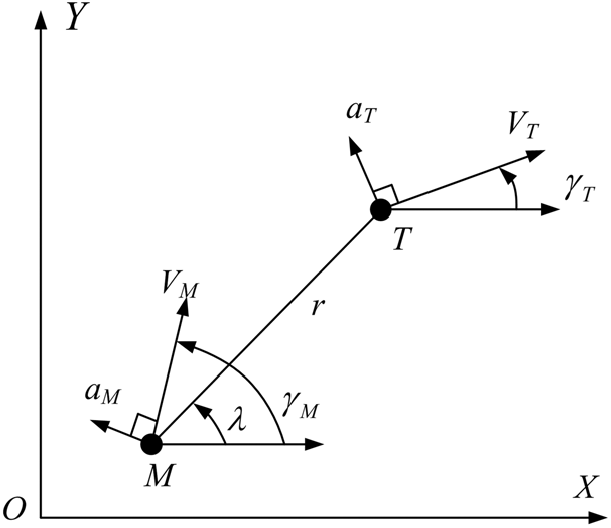
This study considers the impact angle constrained IGC law design problem within the perpendicular plane. Figure 1 depicts a schematic view of 2D planar homing engagement geometry, where
![]() $V_{M} $
and
$V_{M} $
and
![]() $V_{T}$
are missile and target velocities satisfying
$V_{T}$
are missile and target velocities satisfying
![]() $V_{T} /V_{M} >1$
,
$V_{T} /V_{M} >1$
,
![]() $a_{M} $
and
$a_{M} $
and
![]() $a_{T} $
are missile and target accelerations being normal to their corresponding velocities,
$a_{T} $
are missile and target accelerations being normal to their corresponding velocities,
![]() $\gamma _{M} $
and
$\gamma _{M} $
and
![]() $\gamma _{T} $
are missile and target flight-path angles and r and
$\gamma _{T} $
are missile and target flight-path angles and r and
![]() $\lambda $
denote the relative range between the missile and the target and the line-of-sight (LOS) angle, respectively. For simplicity, the missile and the target are regarded as point masses moving with constant velocities.
$\lambda $
denote the relative range between the missile and the target and the line-of-sight (LOS) angle, respectively. For simplicity, the missile and the target are regarded as point masses moving with constant velocities.
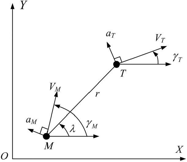
Figure 1. Planar engagement geometry.
The corresponding kinematic engagement equations describing the relative motion between the target and the missile can be formulated as(Reference He, Song and Lin31)
Let
![]() $V_{\lambda } =r\dot{\lambda }$
and differentiating Equations (1) and (2) with respect to time yields that
$V_{\lambda } =r\dot{\lambda }$
and differentiating Equations (1) and (2) with respect to time yields that
Generally, the acceleration along the missile’s velocity cannot be controlled in the terminal guidance phase; hence, only the second-order dynamics between the missile’s normal acceleration
![]() $a_{M} $
and the LOS angle
$a_{M} $
and the LOS angle
![]() $\lambda $
is utilised to address the IGC problem in the terminal guidance phase(Reference Wang, Zheng and Lin32,Reference Wang, Xiong, Wang, Song and Lai33) .
$\lambda $
is utilised to address the IGC problem in the terminal guidance phase(Reference Wang, Zheng and Lin32,Reference Wang, Xiong, Wang, Song and Lai33) .
The missile considered in this study is an aerodynamically controlled vehicle, and the planar dynamics can be given by(Reference He, Song and Lin31)
 $$\left\{ {\matrix{
{\dot \alpha = {1 \over {m{V_M}}}\left( { - {L_f} + mg\cos {\gamma _M}} \right) + {\omega _z}} \hfill \cr
{{{\dot \omega }_z} = {{{M_z}} \over {{J_z}}}} \hfill \cr
{\dot \vartheta = {\omega _z}} \hfill \cr
{\alpha = \vartheta - {\gamma _M}} \hfill \cr
} } \right.$$
in which m is the missile mass,
![]() $\alpha $
denotes the angle-of-attack, g is the acceleration due to gravity,
$\alpha $
denotes the angle-of-attack, g is the acceleration due to gravity,
![]() $J_{z} $
is the moment of inertia,
$J_{z} $
is the moment of inertia,
![]() $\omega _{z} $
represents the pitch angular rate and
$\omega _{z} $
represents the pitch angular rate and
![]() $\vartheta $
is the pitch angle. Besides,
$\vartheta $
is the pitch angle. Besides,
![]() $L_{f} $
and
$L_{f} $
and
![]() $M_{z} $
, representing the aerodynamic lift force and pitch moment without considering direct aerodynamic force from the control surfaces, can be modelled as(Reference He, Song and Lin31)
$M_{z} $
, representing the aerodynamic lift force and pitch moment without considering direct aerodynamic force from the control surfaces, can be modelled as(Reference He, Song and Lin31)
 $$\left\{ {\matrix{
{L = QSc_y^\alpha \alpha } \hfill \cr
{{M_z} = QSLm_z^\alpha \alpha + {{QS{L^2}m_z^{{\omega _z}}} \over {{V_M}}}{\omega _z} + QSLm_z^{{\delta _z}}{\rm{sat}}\left( {{\delta _z}} \right)} \hfill \cr
} } \right.$$
where Q denotes the dynamic pressure, S denote the reference area, L is the reference length and
![]() $\delta _{z} $
is the actuator deflection angle under the following saturation constraint
$\delta _{z} $
is the actuator deflection angle under the following saturation constraint
 \begin{equation}
{\rm sat}\left(\delta _{z} \right)=\left\{\begin{array}{cc} {\delta _{z} } & {{\rm if}\; \left|\delta _{z} \right|\le \delta _{\max } } \\[5pt] {\delta _{\max } sign\left(\delta _{z} \right)} & {{\rm if}\; \left|\delta _{z} \right|>\delta _{\max } } \end{array}\right.
\end{equation}
with
![]() $\delta _{\max } $
being the upper bound. The notation
$\delta _{\max } $
being the upper bound. The notation
![]() $c_{y}^{\alpha } $
is the lift force co-efficient derivative with respect to
$c_{y}^{\alpha } $
is the lift force co-efficient derivative with respect to
![]() $\alpha $
. Similarly,
$\alpha $
. Similarly,
![]() $m_{z}^{\alpha } ,m_{z}^{\omega _{z} } $
, and
$m_{z}^{\alpha } ,m_{z}^{\omega _{z} } $
, and
![]() $m_{z}^{\delta _{z} } $
are the pitch moment co-efficient derivatives with respect to
$m_{z}^{\delta _{z} } $
are the pitch moment co-efficient derivatives with respect to
![]() $\alpha ,\omega _{z} $
, and
$\alpha ,\omega _{z} $
, and
![]() $\delta _{z}$
.
$\delta _{z}$
.
Because of Equations (7) and (8), the missile acceleration can be rewritten as(Reference He, Song and Lin31)
In practical applications, the precise values of the aforementioned aerodynamic parameters cannot be measured in wind-tunnel experiments. Therefore, it is necessary and reasonable to take aerodynamic uncertainties into consideration in IGC design, and then the aforementioned aerodynamic parameters can be further formulated as(Reference He, Song and Lin31)
where the parameters with subscripts n and u indicate the nominal values and uncertain values, respectively.
Usually, the impact angle can be defined as the intersect angle between the velocity vectors of the missile and the target when the interception is achieved(Reference He, Wang and Wang34). Hence, the IGC law considered in this study tries to obtain precise target capture with a desired impact angle
![]() $\gamma _{d} $
, that is
$\gamma _{d} $
, that is
where
![]() $t_{f} $
is the interception time. As indicated in(Reference He, Wang and Wang35) that for a perfect interception (e.g.,
$t_{f} $
is the interception time. As indicated in(Reference He, Wang and Wang35) that for a perfect interception (e.g.,
![]() $\dot{\lambda }=V_{\lambda } =0$
) with an expected impact angle, there always exists a unique desired LOS angle
$\dot{\lambda }=V_{\lambda } =0$
) with an expected impact angle, there always exists a unique desired LOS angle
![]() $\lambda _{d} $
, which can be obtained by(Reference He, Wang and Wang35)
$\lambda _{d} $
, which can be obtained by(Reference He, Wang and Wang35)
where
![]() ${\rm atan}2$
is the arctangent function returning the angle in its appropriate quadrant. Hence, the control objective of the impact angle constrained IGC problem considered in this paper can be stated as designing an IGC law for
${\rm atan}2$
is the arctangent function returning the angle in its appropriate quadrant. Hence, the control objective of the impact angle constrained IGC problem considered in this paper can be stated as designing an IGC law for
![]() $\delta _{z} $
, such that the manoeuvring target interception can be achieved with a desired LOS angle in the presence of aerodynamic uncertainties with actuator saturation constraint.
$\delta _{z} $
, such that the manoeuvring target interception can be achieved with a desired LOS angle in the presence of aerodynamic uncertainties with actuator saturation constraint.
Remark 1. As pointed out in(Reference Zhang, Tang and Guo11,Reference Zhang, Tang and Guo12) , the target flight-path angle
![]() $\gamma _{T} $
can always be measured or predicted by a tracking filter no matter if the target is stationary or manoeuvring. Therefore, it is reasonable to assume that the value of
$\gamma _{T} $
can always be measured or predicted by a tracking filter no matter if the target is stationary or manoeuvring. Therefore, it is reasonable to assume that the value of
![]() $\gamma _{T} $
is known in the IGC law design.
$\gamma _{T} $
is known in the IGC law design.
3.0 IGC LAW DESIGN AND STABILITY ANALYSIS
3.1 IGC law design
In this section, a novel adaptive backstepping-based IGC law is presented to address the impact angle constrained IGC problem with actuator saturation. Before moving on, the following assumption is given firstly, which is usually utilised in the stability analysis.
Assumption 1. There exist two positive constants
![]() $\bar{r}$
and
$\bar{r}$
and
![]() $\underline{r}$
, such that
$\underline{r}$
, such that
![]() $\underline{r} < r < \bar{r}$
is satisfied during the overall guidance phase. Moreover, the lower bound
$\underline{r} < r < \bar{r}$
is satisfied during the overall guidance phase. Moreover, the lower bound
![]() $\underline{r}$
can be given according to the target physical size.
$\underline{r}$
can be given according to the target physical size.
With the above assumption in mind, the proposed IGC law will be given step by step in the following text.
Step 1: Let
![]() $s_{1} =\left(\lambda -\lambda _{d} \right)/r$
; differentiating
$s_{1} =\left(\lambda -\lambda _{d} \right)/r$
; differentiating
![]() $s_{1} $
with respect to time yields that
$s_{1} $
with respect to time yields that
where
![]() $V_{\lambda }^{*} $
denotes a virtual control input, and
$V_{\lambda }^{*} $
denotes a virtual control input, and
![]() $\Delta _{1} =-a_{T} /V_{T} $
is considered as an external disturbance with unknown upper bound
$\Delta _{1} =-a_{T} /V_{T} $
is considered as an external disturbance with unknown upper bound
![]() $d_{1} $
, that is
$d_{1} $
, that is
![]() $\left|\Delta _{1} \right|\le d_{1} $
. To stabilise the system shown in Equation (14), one can select the following virtual control input:
$\left|\Delta _{1} \right|\le d_{1} $
. To stabilise the system shown in Equation (14), one can select the following virtual control input:
where
![]() $k_{1} >0$
and
$k_{1} >0$
and
![]() $\varepsilon _{1} >0$
are design parameters, and
$\varepsilon _{1} >0$
are design parameters, and
![]() $\hat{d}_{1} $
is the estimation of
$\hat{d}_{1} $
is the estimation of
![]() $d_{1} $
governed by the following adaptive law
$d_{1} $
governed by the following adaptive law
with constants
![]() $c_{1} >0$
and
$c_{1} >0$
and
![]() $\sigma _{1} >0$
.
$\sigma _{1} >0$
.
Step 2: Let
![]() $s_{2} =\left(V_{\lambda } -V_{\lambda }^{*} \right)/r$
, differentiating
$s_{2} =\left(V_{\lambda } -V_{\lambda }^{*} \right)/r$
, differentiating
![]() $s_{2} $
based on Equations (6) and (7) with respect to time yields that
$s_{2} $
based on Equations (6) and (7) with respect to time yields that
 $$\matrix{
{{{\dot s}_2} = {1 \over r}\left[ { - {{QSc_{y,n}^\alpha \cos \left( {{\gamma _M} - \lambda } \right)} \over m}\alpha - \dot r{s_2} - \dot \lambda \dot r - \dot V_\lambda ^*} \right.} \hfill \cr
{\quad \quad \;\left. {{\mkern 1mu} {\mkern 1mu} + g\cos {\gamma _M}\cos \left( {{\gamma _M} - \lambda } \right) + {\Delta _2}} \right]} \hfill \cr
} $$
 $$\matrix{
{\quad = {1 \over r}\left[ { - {{QSc_{y,n}^\alpha \cos \left( {{\gamma _M} - \lambda } \right)} \over m}{\alpha ^*} - {{QSc_{y,n}^\alpha \cos \left( {{\gamma _M} - \lambda } \right)} \over m}\left( {\alpha - {\alpha ^*}} \right)} \right.} \hfill \cr
{\quad \quad \;\left. {{\mkern 1mu} {\mkern 1mu} - \dot r{s_2} - \dot \lambda \dot r - \dot V_\lambda ^* + g\cos {\gamma _M}\cos \left( {{\gamma _M} - \lambda } \right) + {\Delta _2}} \right]} \hfill \cr
} $$
where
![]() $\alpha ^{*} $
denotes a virtual control input, and
$\alpha ^{*} $
denotes a virtual control input, and
![]() $\Delta _{2} =a_{T} \cos \left(\gamma _{T} -\lambda \right)-\frac{QSc_{y,u}^{\alpha } \alpha \cos \left(\gamma _{M} -\lambda \right)}{m} $
is considered as an external disturbance with unknown upper bound
$\Delta _{2} =a_{T} \cos \left(\gamma _{T} -\lambda \right)-\frac{QSc_{y,u}^{\alpha } \alpha \cos \left(\gamma _{M} -\lambda \right)}{m} $
is considered as an external disturbance with unknown upper bound
![]() $d_{2} $
, that is
$d_{2} $
, that is
![]() $\left|\Delta _{2} \right|\le d_{2} $
. For the subsystem in Equation (17), select the following virtual control input:
$\left|\Delta _{2} \right|\le d_{2} $
. For the subsystem in Equation (17), select the following virtual control input:
 $$\matrix{
{{\alpha ^*} = {m \over {QSc_{y,n}^\alpha \cos \left( {{\gamma _M} - \lambda } \right)}}\left[ { - \dot \lambda \dot r - \dot V_\lambda ^* + g\cos {\gamma _M}\cos \left( {{\gamma _M} - \lambda } \right)} \right.} \hfill \cr
{\left. {\quad \quad \quad \quad \quad \quad \quad \quad \quad \quad {\mkern 1mu} {\mkern 1mu} + {k_2}{s_2} + {s_1} + {{{s_2}\hat d_2^2} \over {2{\varepsilon _2}}} - \dot r{s_2}} \right]} \hfill \cr
} $$
where
![]() $k_{2} >0$
and
$k_{2} >0$
and
![]() $\varepsilon _{2} >0$
are design parameters, and
$\varepsilon _{2} >0$
are design parameters, and
![]() $\hat{d}_{2} $
is the estimation of
$\hat{d}_{2} $
is the estimation of
![]() $d_{2} $
governed by the following adaptive law
$d_{2} $
governed by the following adaptive law
with constants
![]() $c_{2} >0$
and
$c_{2} >0$
and
![]() $\sigma _{2} >0$
.
$\sigma _{2} >0$
.
Step 3: Let
![]() $s_{3} =\alpha -\alpha ^{*} $
, and differentiating
$s_{3} =\alpha -\alpha ^{*} $
, and differentiating
![]() $s_{3} $
with respect to time yields that
$s_{3} $
with respect to time yields that
where
![]() $\omega _{z}^{*} $
denotes virtual control input, and
$\omega _{z}^{*} $
denotes virtual control input, and
![]() $\Delta _{3} =-\frac{QSc_{y,u}^{\alpha } \alpha }{mV_{M} } $
is considered as an external disturbance with unknown upper bound
$\Delta _{3} =-\frac{QSc_{y,u}^{\alpha } \alpha }{mV_{M} } $
is considered as an external disturbance with unknown upper bound
![]() $d_{3} $
, that is
$d_{3} $
, that is
![]() $\left|\Delta _{3} \right|\le d_{3}$
. For the subsystem in Equation (20), consider the following virtual control law:
$\left|\Delta _{3} \right|\le d_{3}$
. For the subsystem in Equation (20), consider the following virtual control law:
 \begin{equation}
\begin{array}{l} {\omega _{z}^{*} =-k_{3} s_{3} +\frac{QSc_{y,n}^{\alpha } \cos \left(\gamma _{M} -\lambda \right)}{mr} s_{2} +\frac{QSc_{y.n}^{\alpha } \alpha }{mV_{M} } } \\ {\quad \quad -\frac{g\cos \gamma _{M} }{V_{M} } +\dot{\alpha }^{*} -\frac{s_{3} \hat{d}_{3}^{2} }{2\varepsilon _{3} } } \end{array}
\end{equation}
where
![]() $k_{3} >0$
and
$k_{3} >0$
and
![]() $\varepsilon _{3} >0$
are design parameters, and
$\varepsilon _{3} >0$
are design parameters, and
![]() $\hat{d}_{3} $
is the estimation of
$\hat{d}_{3} $
is the estimation of
![]() $d_{3} $
governed by the following adaptive law
$d_{3} $
governed by the following adaptive law
with constants
![]() $c_{3} >0$
and
$c_{3} >0$
and
![]() $\sigma _{3} >0$
.
$\sigma _{3} >0$
.
Step 4: Let
![]() $s_{4} =\omega _{z} -\omega _{z}^{*} $
, and differentiating
$s_{4} =\omega _{z} -\omega _{z}^{*} $
, and differentiating
![]() $s_{4} $
with respect to time yields that
$s_{4} $
with respect to time yields that
 $$\matrix{
{{{\dot s}_4} = {{QSLm_{z,n}^{{\delta _z}}} \over {{J_z}}}{\rm{sat}}\left( {{\delta _z}} \right) + {{QSLm_{z,n}^\alpha \alpha } \over {{J_z}}} + {{QS{L^2}m_{z.n}^{{\omega _z}}{\omega _z}} \over {{J_z}{V_M}}} - \dot \omega _z^* + {\Delta _4}} \hfill \cr
{\quad = {{QSLm_{z,n}^{{\delta _z}}} \over {{J_z}}}{\delta _z} + {{QSLm_{z,n}^\alpha \alpha } \over {{J_z}}} + {{QS{L^2}m_{z.n}^{{\omega _z}}{\omega _z}} \over {{J_z}{V_M}}} - \dot \omega _z^* + {\Delta _4} + {{QSLm_{z,n}^{{\delta _z}}} \over {{J_z}}}{{\bar \delta }_z}} \hfill \cr
} $$
where
![]() $\Delta _{4} =\frac{QSLm_{z,u}^{\alpha } \alpha }{J_{z} } +\frac{QSL^{2} m_{z,u}^{\omega _{z} } \omega _{z} }{J_{z} V_{M} } +\frac{QSLm_{z,u}^{\delta _{z} } {\rm sat}\left(\delta _{z} \right)}{J_{z} } $
is considered as an external disturbance with unknown upper bound
$\Delta _{4} =\frac{QSLm_{z,u}^{\alpha } \alpha }{J_{z} } +\frac{QSL^{2} m_{z,u}^{\omega _{z} } \omega _{z} }{J_{z} V_{M} } +\frac{QSLm_{z,u}^{\delta _{z} } {\rm sat}\left(\delta _{z} \right)}{J_{z} } $
is considered as an external disturbance with unknown upper bound
![]() $d_{4} $
, that is
$d_{4} $
, that is
![]() $\left|\Delta _{4} \right|\le d_{4} $
and
$\left|\Delta _{4} \right|\le d_{4} $
and
![]() $\bar{\delta }_{z} ={\rm sat}\left(\delta _{z} \right)-\delta _{z} $
is utilised to deal with the input saturation. We pass
$\bar{\delta }_{z} ={\rm sat}\left(\delta _{z} \right)-\delta _{z} $
is utilised to deal with the input saturation. We pass
![]() $\bar{\delta }_{z} $
through a first-order filter with a time constant
$\bar{\delta }_{z} $
through a first-order filter with a time constant
![]() $\tau _{\delta } $
to obtain a filtered virtual control
$\tau _{\delta } $
to obtain a filtered virtual control
![]() $\delta _{e} $
:
$\delta _{e} $
:
 \begin{equation}
\dot{\delta }_{e} =-\frac{1}{\tau _{\delta } } \delta _{e} +\left|\frac{QSLm_{z,n}^{\delta _{z} } }{J_{z} } \right|\bar{\delta }_{z} .
\end{equation}
in which the design variable is selected as
 \begin{equation}
\frac{1}{\tau _{\delta } } =k_{\delta } +\frac{\left|\frac{4QSLm_{z,n}^{\delta _{z} } }{J_{z} } \right|\left|s_{4} \right|\left|\bar{\delta }_{z} \right|+\left(\frac{QSLm_{z,n}^{\delta _{z} } }{J_{z} } \right)^{2} \bar{\delta }_{z}^{2} }{4\delta _{e}^{2} +\varphi \left(\delta _{e} \right)}
\end{equation}
with
![]() $k_{\delta } >0$
and
$k_{\delta } >0$
and
![]() $\varphi \left(\delta _{e} \right)=\left\{\begin{array}{cc} {0} & {{\rm if}\; \delta _{e} \ne 0} \\ {1} & {{\rm if}\; \delta _{e} =0} \end{array}\right.$
.
$\varphi \left(\delta _{e} \right)=\left\{\begin{array}{cc} {0} & {{\rm if}\; \delta _{e} \ne 0} \\ {1} & {{\rm if}\; \delta _{e} =0} \end{array}\right.$
.
For the subsystem in Equation (23), consider the following virtual control law:
 \begin{equation}
\delta _{z} =\frac{J_{z} }{QSLm_{z,n}^{\delta _{z} } } \left(-k_{4} s_{4} -s_{3} -\frac{QSLm_{z,n}^{\alpha } \alpha }{J_{z} } -\frac{QSL^{2} m_{z.n}^{\omega _{z} } \omega _{z} }{J_{z} V_{M} } +\dot{\omega }_{z}^{*} -\frac{s_{4} \hat{d}_{4}^{2} }{2\varepsilon _{4} } \right)
\end{equation}
where
![]() $k_{4} >0$
and
$k_{4} >0$
and
![]() $\varepsilon _{4} >0$
are design parameters, and
$\varepsilon _{4} >0$
are design parameters, and
![]() $\hat{d}_{4} $
is the estimation of
$\hat{d}_{4} $
is the estimation of
![]() $d_{4} $
governed by the following adaptive law
$d_{4} $
governed by the following adaptive law
with constants
![]() $c_{4} >0$
and
$c_{4} >0$
and
![]() $\sigma _{4} >0$
.
$\sigma _{4} >0$
.
The aforementioned presentation gives an IGC law design approach based on the typical backstepping design. It can be seen from Equations (18), (21) and (26) that the virtual control inputs' derivative
![]() $\dot{V}_{\lambda }^{*} $
,
$\dot{V}_{\lambda }^{*} $
,
![]() $\dot{\alpha }^{*} $
and
$\dot{\alpha }^{*} $
and
![]() $\dot{\omega }_{z}^{*} $
are included in the IGC law, while these variables may not be easily acquired in reality, and an direct differential of
$\dot{\omega }_{z}^{*} $
are included in the IGC law, while these variables may not be easily acquired in reality, and an direct differential of
![]() $V_{\lambda }^{*}$
,
$V_{\lambda }^{*}$
,
![]() $\alpha ^{*} $
and
$\alpha ^{*} $
and
![]() $\omega _{z}^{*} $
leads to the so-called “explosion of complexity” in the sequel. To cope with this problem, a fixed-time differentiator is proposed based on the result in(Reference Basin, Yu and Shtessel36) as a feasible way to reconstruct
$\omega _{z}^{*} $
leads to the so-called “explosion of complexity” in the sequel. To cope with this problem, a fixed-time differentiator is proposed based on the result in(Reference Basin, Yu and Shtessel36) as a feasible way to reconstruct
![]() $\dot{V}_{\lambda }^{*}$
,
$\dot{V}_{\lambda }^{*}$
,
![]() $\dot{\alpha }^{*} $
and
$\dot{\alpha }^{*} $
and
![]() $\dot{\omega }_{z}^{*} $
in the IGC law design. Accordingly, we have
$\dot{\omega }_{z}^{*} $
in the IGC law design. Accordingly, we have
where
![]() $z_{d} $
can be set as
$z_{d} $
can be set as
![]() $V_{\lambda }^{*}$
,
$V_{\lambda }^{*}$
,
![]() $\alpha ^{*} $
or
$\alpha ^{*} $
or
![]() $\omega _{z}^{*}$
,
$\omega _{z}^{*}$
,
![]() $z_{1} $
is the estimated value of
$z_{1} $
is the estimated value of
![]() $z_{d}$
$z_{d}$
![]() $z_{2} $
is the estimated derivative of
$z_{2} $
is the estimated derivative of
![]() $z_{d} $
corresponding to
$z_{d} $
corresponding to
![]() $\dot{V}_{\lambda }^{*}$
$\dot{V}_{\lambda }^{*}$
![]() $\dot{\alpha }^{*} $
or
$\dot{\alpha }^{*} $
or
![]() $\dot{\omega }_{z}^{*}$
, and
$\dot{\omega }_{z}^{*}$
, and
![]() $\tau _{1}$
,
$\tau _{1}$
,
![]() $\tau _{2} $
are observer gains. Moreover,
$\tau _{2} $
are observer gains. Moreover,
![]() $a_{1} \in \left(1-\upsilon ,1\right)$
,
$a_{1} \in \left(1-\upsilon ,1\right)$
,
![]() $b_{1} \in \left(1,1+\upsilon \right)$
,
$b_{1} \in \left(1,1+\upsilon \right)$
,
![]() $a_{2} =2a_{1} -1$
and
$a_{2} =2a_{1} -1$
and
![]() $b_{2} =2a_{2} -1$
where
$b_{2} =2a_{2} -1$
where
![]() $\upsilon $
is a sufficiently small constant. It was indicated in(Reference Basin, Yu and Shtessel36) that, based on the differentiator Equation (28), the estimation errors are globally bounded and can converge to zero within a bounded finite time
$\upsilon $
is a sufficiently small constant. It was indicated in(Reference Basin, Yu and Shtessel36) that, based on the differentiator Equation (28), the estimation errors are globally bounded and can converge to zero within a bounded finite time
![]() $T_{sd} >0$
. Considering this, the virtual control inputs presented in the aforementioned text can be transformed into the following form:
$T_{sd} >0$
. Considering this, the virtual control inputs presented in the aforementioned text can be transformed into the following form:
 $$\left\{ {\matrix{
{V_\lambda ^* = - {k_1}\left( {\lambda - {\lambda _d}} \right) + \dot r\left( {\lambda - {\lambda _d}} \right) - {{r{s_1}\hat d_1^2} \over {2{\varepsilon _1}}}} \hfill \cr
{\matrix{
{{\alpha ^*} = {m \over {QSc_{y,n}^\alpha \cos \left( {{\gamma _M} - \lambda } \right)}}\left[ { - \dot \lambda \dot r - {{\dot V}_{\lambda ,d}} + g\cos {\gamma _M}\cos \left( {{\gamma _M} - \lambda } \right)} \right.} \hfill \cr
{\left. {\quad \quad \quad \quad \quad \quad \quad \quad \quad \quad {\mkern 1mu} {\mkern 1mu} + {k_2}{s_2} + {s_1} + {{{s_2}\hat d_2^2} \over {2{\varepsilon _2}}} - \dot r{s_2}} \right]} \hfill \cr
} } \hfill \cr
{\matrix{
{\omega _z^* = - {k_3}{s_3} + {{QSc_{y,n}^\alpha \cos \left( {{\gamma _M} - \lambda } \right)} \over {mr}}{s_2} + {{QSc_{y.n}^\alpha \alpha } \over {m{V_M}}}} \hfill \cr
{\quad \quad - {{g\cos {\gamma _M}} \over {{V_M}}} + {{\dot \alpha }_d} - {{{s_3}\hat d_3^2} \over {2{\varepsilon _3}}}} \hfill \cr
} } \hfill \cr
{{\delta _z} = {{{J_z}} \over {QSLm_{z,n}^{{\delta _z}}}}\left( { - {k_4}{s_4} - {s_3} + - {{QSLm_{z,n}^\alpha \alpha } \over {{J_z}}} - {{QS{L^2}m_{z.n}^{{\omega _z}}{\omega _z}} \over {{J_z}{V_M}}} - {{{s_4}\hat d_4^2} \over {2{\varepsilon _4}}} + {{\dot \omega }_{z,d}}} \right)} \hfill \cr
} } \right.$$
where
![]() $\dot{V}_{\lambda ,d}^{}$
,
$\dot{V}_{\lambda ,d}^{}$
,
![]() $\dot{\alpha }_{d} $
and
$\dot{\alpha }_{d} $
and
![]() $\dot{\omega }_{z,d}^{} $
are the estimations of
$\dot{\omega }_{z,d}^{} $
are the estimations of
![]() $\dot{V}_{\lambda }^{*} $
,
$\dot{V}_{\lambda }^{*} $
,
![]() $\dot{\alpha }^{*} $
and
$\dot{\alpha }^{*} $
and
![]() $\dot{\omega }_{z}^{*} $
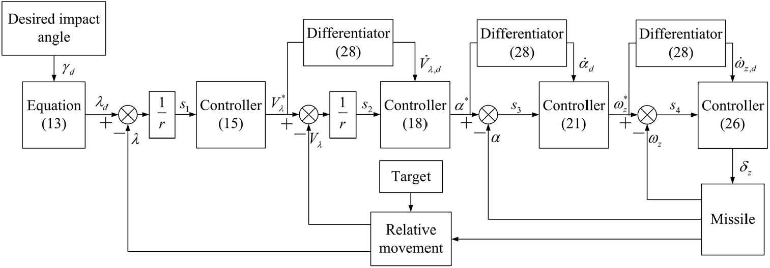
, respectively, and can be obtained based on the fixed-time differentiator in Equation (28). The overall controller structure is shown in Fig. 2.
$\dot{\omega }_{z}^{*} $
, respectively, and can be obtained based on the fixed-time differentiator in Equation (28). The overall controller structure is shown in Fig. 2.
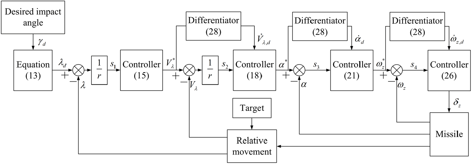
Figure 2. Controller structure.
Remark 2. In the typical DSC design, a first-order filter is commonly used to cope with the ‘explosion of complexity’ problem, where a sufficiently small time constant is required to obtain fast and precise estimation leading to the peaking phenomenon during the initial moment. Compared with the typical DSC design, the fixed-time differentiator in Equation (28) can avoid this unexpected phenomenon efficiently.
Remark 3. By using the adaptation laws in Equations (16), (19), (22) and (27), the upper bounds of the target acceleration and the uncertain aerodynamics are not required in the proposed IGC law, which helps to broaden the scope of practical applications. Moreover, the
![]() $\sigma {\rm -modification}$
–modification terms are introduced in Equations (16), (17), (22) and (27) to avoid the over-estimation of uncertain parameters. This contributes to improve the steady-state performance of the closed-loop system.
$\sigma {\rm -modification}$
–modification terms are introduced in Equations (16), (17), (22) and (27) to avoid the over-estimation of uncertain parameters. This contributes to improve the steady-state performance of the closed-loop system.
3.2 Stability analysis
Based on the above analysis, the closed-loop system can be rewritten as
 $$\left\{ {\matrix{
{{{\dot s}_1} = {1 \over r}\left( { - {k_1}{s_1} + {\Delta _1} - {{{s_1}\hat d_1^2} \over {2{\varepsilon _1}}} + {s_2}} \right)} \hfill \cr
{{{\dot s}_2} = {1 \over r}\left( { - {k_2}{s_2} + {\Delta _2} - {{{s_2}\hat d_2^2} \over {2{\varepsilon _2}}} - {s_1} - {{QSc_{y,n}^\alpha \cos \left( {{\gamma _M} - \lambda } \right)} \over m}{s_3} + {{\dot V}_{\lambda ,d}} - \dot V_\lambda ^*} \right)} \hfill \cr
{{{\dot s}_3} = - {k_3}{s_3} + {\Delta _3} - {{{s_3}\hat d_3^2} \over {2{\varepsilon _3}}} + {{QSc_{y,n}^\alpha \cos \left( {{\gamma _M} - \lambda } \right)} \over {mr}}{s_2} + {s_4} + {{\dot \alpha }_d} - {{\dot \alpha }^*}} \hfill \cr
{{{\dot s}_4} = - {k_4}{s_4} - {s_3} + {\Delta _4} - {{{s_4}\hat d_4^2} \over {2{\varepsilon _4}}} + {{\dot \omega }_{z,d}} - \dot \omega _z^* + {{QSLm_{z,n}^{{\delta _z}}} \over {{J_z}}}{{\bar \delta }_z}} \hfill \cr
} } \right.$$
Next, the following theorem is given to show the main results achieved in this study.
Theorem 1
For the error systems in Equation (30) with the adaptation laws of Equations (16), (19), (22) and (27) and the fixed-time differentiator in Equation (28), the closed-loop errors can be stabilised in the arbitrarily small neighbourhood of the origin.
Proof. Consider the following Lyapunov candidate:
where
![]() $\tilde{d}_{i} =d_{i} -\hat{d}_{i} \left(i=1,...,4\right)$
denote the estimation error of the lumped disturbance.
$\tilde{d}_{i} =d_{i} -\hat{d}_{i} \left(i=1,...,4\right)$
denote the estimation error of the lumped disturbance.
Differentiating V with respect to time along trajectories, Equation (30) yields:
 $$\matrix{
{\dot V = \sum\limits_{i = 1}^4 {{s_i}} {{\dot s}_i} - {1 \over {{c_i}}}\sum\limits_{i = 1}^4 {{{\tilde d}_i}} {{\dot \hat d}_i} + {\delta _e}{{\dot \delta }_e}} \hfill \cr
{\;\;\; = {1 \over r}\left( { - {k_1}s_1^2 - {{s_1^2\hat d_1^2} \over {2{\varepsilon _1}}} + {s_1}{\Delta _1} - {{\tilde d}_1}\left| {{s_1}} \right|} \right) + {1 \over r}\left( { - {k_2}s_2^2 - {{s_2^2\hat d_2^2} \over {2{\varepsilon _2}}} + {s_2}{\Delta _2} - {{\tilde d}_2}\left| {{s_2}} \right|} \right)} \hfill \cr
{\quad \;{\mkern 1mu} + \left( { - {k_3}s_3^2 - {{s_3^2\hat d_3^2} \over {2{\varepsilon _3}}} + {s_3}{\Delta _3} - {{\tilde d}_3}\left| {{s_3}} \right|} \right) + \left( { - {k_4}s_4^2 - {{s_4^2\hat d_4^2} \over {2{\varepsilon _4}}} + {s_4}{\Delta _4} - {{\tilde d}_4}\left| {{s_4}} \right|} \right)} \hfill \cr
{\quad \;{\mkern 1mu} - {1 \over {{\tau _\delta }}}\delta _e^2 + {{{s_2}} \over r}\left( {{{\dot V}_{\lambda ,d}} - \dot V_\lambda ^*} \right) + {s_3}\left( {{{\dot \alpha }_d} - {{\dot \alpha }^*}} \right) + {s_4}\left( {{{\dot \omega }_{z,d}} - \dot \omega _z^*} \right)} \hfill \cr
{\quad \;{\mkern 1mu} + {{QSLm_{z,n}^{{\delta _z}}} \over {{J_z}}}{{\bar \delta }_z}{s_4} + \left| {{{QSLm_{z,n}^{{\delta _z}}} \over {{J_z}}}} \right|{{\bar \delta }_z}{\delta _e} + \sum\limits_{i = 1}^4 {{{{\sigma _i}} \over {{c_i}}}} {{\tilde d}_i}{{\hat d}_i}.} \hfill \cr
} $$
Applying the following facts
 $$\left\{ {\matrix{
{{s_i}{\Delta _i} \le \left| {{s_i}} \right|\left| {{\Delta _i}} \right| \le \left| {{s_i}} \right|{d_i}} \hfill \cr
{ - {{s_i^2\hat d_i^2} \over {2{\varepsilon _i}}} \le - \left| {{s_i}} \right|{{\hat d}_i} + {{{\varepsilon _i}} \over 2}} \hfill \cr
{{{{\sigma _i}} \over {{c_i}}}{{\tilde d}_i}{{\hat d}_i} \le - {{{\sigma _i}} \over {2{c_i}}}\tilde d_i^2 + {{{\sigma _i}} \over {2{c_i}}}d_i^2} \hfill \cr
} } \right.\quad i = 1,...,4$$
to Equation (32) yields
 $$\matrix{
{\dot V \le - {{{k_1}} \over r}s_1^2 - {{{k_2}} \over r}s_2^2 - {k_3}s_3^2 - {k_4}s_4^2 - \sum\limits_{i = 1}^4 {{{{\sigma _i}} \over {2{c_i}}}} \tilde d_i^2} \hfill \cr
{\quad \;\; + \sum\limits_{i = 1}^4 {{{{\sigma _i}} \over {2{c_i}}}} d_i^2 + {{{\varepsilon _1} + {\varepsilon _1}} \over {2r}} + {{{\varepsilon _3} + {\varepsilon _4}} \over 2}} \hfill \cr
{\quad \;\;\; + {{{s_2}} \over r}\left( {{{\dot V}_{\lambda ,d}} - \dot V_\lambda ^*} \right) + {s_3}\left( {{{\dot \alpha }_d} - {{\dot \alpha }^*}} \right) + {s_4}\left( {{{\dot \omega }_{z,d}} - \dot \omega _z^*} \right){\mkern 1mu} } \hfill \cr
{\quad \;\;\; + \left| {{{QSLm_{z,n}^{{\delta _z}}} \over {{J_z}}}} \right|\left| {{{\bar \delta }_z}} \right|\left| {{s_4}} \right| + \left| {{{QSLm_{z,n}^{{\delta _z}}} \over {{J_z}}}} \right|{{\bar \delta }_z}{\delta _e} - {1 \over {{\tau _\delta }}}\delta _e^2} \hfill \cr
{\;\;{\mkern 1mu} \le - {{{k_1}} \over r}s_1^2 - \left( {{{2{k_2} - 1} \over {2r}}} \right)s_2^2 - \left( {{k_3} - {1 \over 2}} \right)s_3^2 - \left( {{k_4} - {1 \over 2}} \right)s_4^2} \hfill \cr
{\quad \;\; - \sum\limits_{i = 1}^4 {{{{\sigma _i}} \over {2{c_i}}}} \tilde d_i^2 - \left( {{k_\delta } - 1} \right)\delta _e^2 + \sum\limits_{i = 1}^4 {{{{\sigma _i}} \over {2{c_i}}}} d_i^2 + {{{\varepsilon _1} + {\varepsilon _1}} \over {2r}} + {{{\varepsilon _3} + {\varepsilon _4}} \over 2}} \hfill \cr
{\quad \;\; + {{{{\left( {{{\dot V}_{\lambda ,d}} - \dot V_\lambda ^*} \right)}^2}} \over {2r}} + {{{{\left( {{{\dot \alpha }_d} - {{\dot \alpha }^*}} \right)}^2}} \over 2} + {{{{\left( {{{\dot \omega }_{z,d}} - \dot \omega _z^*} \right)}^2}} \over 2}{\mkern 1mu} } \hfill \cr
{\;\;{\mkern 1mu} \le - 2{\kappa _1}V + {\kappa _2} + {\kappa _3}} \hfill \cr
} $$
where
 $$\matrix{
{{\kappa _1} = \min \left\{ {{{{k_1}} \over r},\;{{2{k_2} - 1} \over {2r}},\;{{2{k_3} - 1} \over 2},\;{{2{k_4} - 1} \over 2},\;{{{\sigma _1}} \over 2},\;{{{\sigma _2}} \over 2},\;{{{\sigma _3}} \over 2},\;{{{\sigma _4}} \over 2},{k_\delta } - 1} \right\}} \cr
{{\kappa _2} = \sum\limits_{i = 1}^4 {{{{\sigma _i}} \over {2{c_i}}}} d_i^2 + {{{\varepsilon _1} + {\varepsilon _1}} \over {2r}} + {{{\varepsilon _3} + {\varepsilon _4}} \over 2}} \cr
{{\kappa _3} = {{{{\left( {{{\dot V}_{\lambda ,d}} - \dot V_\lambda ^*} \right)}^2}} \over {2r}} + {{{{\left( {{{\dot \alpha }_d} - {{\dot \alpha }^*}} \right)}^2}} \over 2} + {{{{\left( {{{\dot \omega }_{z,d}} - \dot \omega _z^*} \right)}^2}} \over 2}} \cr
} $$
According to Assumption 1,
![]() $\kappa _{1}$
and
$\kappa _{1}$
and
![]() $\kappa _{2}$
are both bounded. Additionally, Theorem 1 indicates that
$\kappa _{2}$
are both bounded. Additionally, Theorem 1 indicates that
![]() $\left|\dot{V}_{\lambda ,d} -\dot{V}_{\lambda }^{*} \right|,\; \left|\dot{\alpha }_{d} -\dot{\alpha }^{*} \right|$
and
$\left|\dot{V}_{\lambda ,d} -\dot{V}_{\lambda }^{*} \right|,\; \left|\dot{\alpha }_{d} -\dot{\alpha }^{*} \right|$
and
![]() $\left|\dot{\omega }_{z,d} -\dot{\omega }_{z}^{*} \right|$
are globally bounded, which means that
$\left|\dot{\omega }_{z,d} -\dot{\omega }_{z}^{*} \right|$
are globally bounded, which means that
![]() $\kappa _{3} $
is also bounded. Consequently, selecting parameters
$\kappa _{3} $
is also bounded. Consequently, selecting parameters
![]() $k_{2} >1/2,\; k_{3} >1/2,\; k_{4} >1/2$
and
$k_{2} >1/2,\; k_{3} >1/2,\; k_{4} >1/2$
and
![]() $k_{\delta } >1$
yields that
$k_{\delta } >1$
yields that
![]() $\kappa _{1} >0$
. With this in mind, it follows from Equation (34) that
$\kappa _{1} >0$
. With this in mind, it follows from Equation (34) that
which means that the error states are bounded during the convergent phase of the fixed-time differentiator.
Furthermore, as indicated in(Reference Basin, Yu and Shtessel36), the estimation errors
![]() $\left|\dot{V}_{\lambda ,d} -\dot{V}_{\lambda }^{*} \right|,\; \left|\dot{\alpha }_{d} -\dot{\alpha }^{*} \right|$
and
$\left|\dot{V}_{\lambda ,d} -\dot{V}_{\lambda }^{*} \right|,\; \left|\dot{\alpha }_{d} -\dot{\alpha }^{*} \right|$
and
![]() $\left|\dot{\omega }_{z,d} -\dot{\omega }_{z}^{*} \right|$
can converge to zero within a bounded finite time
$\left|\dot{\omega }_{z,d} -\dot{\omega }_{z}^{*} \right|$
can converge to zero within a bounded finite time
![]() $T_{sd} >0$
, that is,
$T_{sd} >0$
, that is,
![]() $\kappa _{3} =0$
holds for all
$\kappa _{3} =0$
holds for all
![]() $t>T_{sd}$
. Considering this, it follows from Equations (34) and (35) that when
$t>T_{sd}$
. Considering this, it follows from Equations (34) and (35) that when
![]() $t>T_{sd} $
, the following inequality holds.
$t>T_{sd} $
, the following inequality holds.
The above analysis indicates all error signals are uniformly and ultimately bounded by
![]() $\frac{\kappa _{2} }{2\kappa _{1} } $
. This completes the proof of Theorem 1. Moreover, tuning design parameters appropriately, such that the upper bound
$\frac{\kappa _{2} }{2\kappa _{1} } $
. This completes the proof of Theorem 1. Moreover, tuning design parameters appropriately, such that the upper bound
![]() $\frac{\kappa _{2} }{2\kappa _{1} } $
is arbitrarily small, helps to improve the steady performance of the proposed IGC law.
$\frac{\kappa _{2} }{2\kappa _{1} } $
is arbitrarily small, helps to improve the steady performance of the proposed IGC law.
4.0 SIMULATION RESULTS
This section carries out numerical simulations to verify the performance of the proposed IGC law, where a typical air defence interception engagement is considered. The target's acceleration is assumed to be
![]() $a_{T} =10\sin \left(0.1\pi t\right) \; {\rm m/s}^{{\rm 2}}$
. The nominal aerodynamic parameters are listed as follows:
$a_{T} =10\sin \left(0.1\pi t\right) \; {\rm m/s}^{{\rm 2}}$
. The nominal aerodynamic parameters are listed as follows:
 $$\matrix{
{{{QSc_{y,n}^\alpha } \over {m{V_M}}} = 0.3487,} & {{{QSLm_{z,n}^\alpha } \over {{J_z}}} = - 17.801,} \cr
{{{QS{L^2}m_{z,n}^{{\omega _z}}} \over {{J_z}{V_M}}} = - 0.2741,} & {{{QSLm_{z,n}^{{\delta _z}}} \over {{J_z}}} = - 56.267.} \cr
} $$
The aerodynamic coefficients are assumed to have 30% uncertain variations with respect to their nominal values in this paper. The maximum of the fin deflection angle is
![]() $\delta _{\max } =30\; {\rm Deg}$
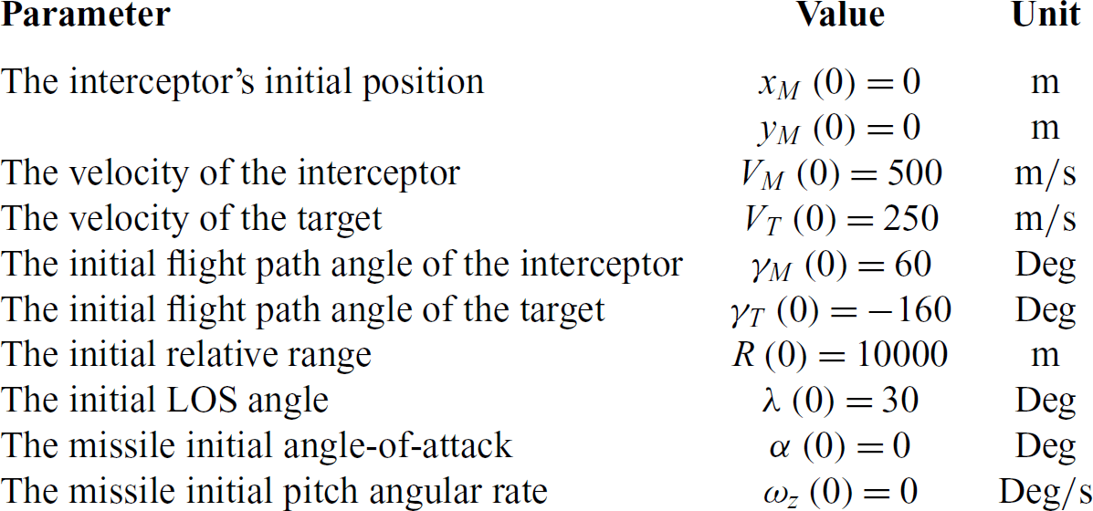
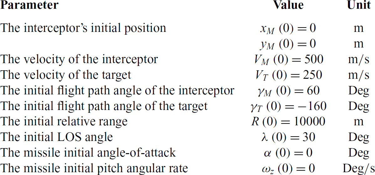
. The initial conditions of the interceptor and the target are given in Table 1.
$\delta _{\max } =30\; {\rm Deg}$
. The initial conditions of the interceptor and the target are given in Table 1.
Table 1 Initial parameters for simulation
4.1 Interception with different desired impact angles
In this case, the simulation results of weaving target interception with various desired impact angles are investigated. The desired impact angles
![]() $\gamma _{d} $
are chosen as
$\gamma _{d} $
are chosen as
![]() $-120\; {\rm Deg},\; -150\; {\rm Deg}, -180\; {\rm Deg}$
and
$-120\; {\rm Deg},\; -150\; {\rm Deg}, -180\; {\rm Deg}$
and
![]() $-210\; {\rm Deg}$
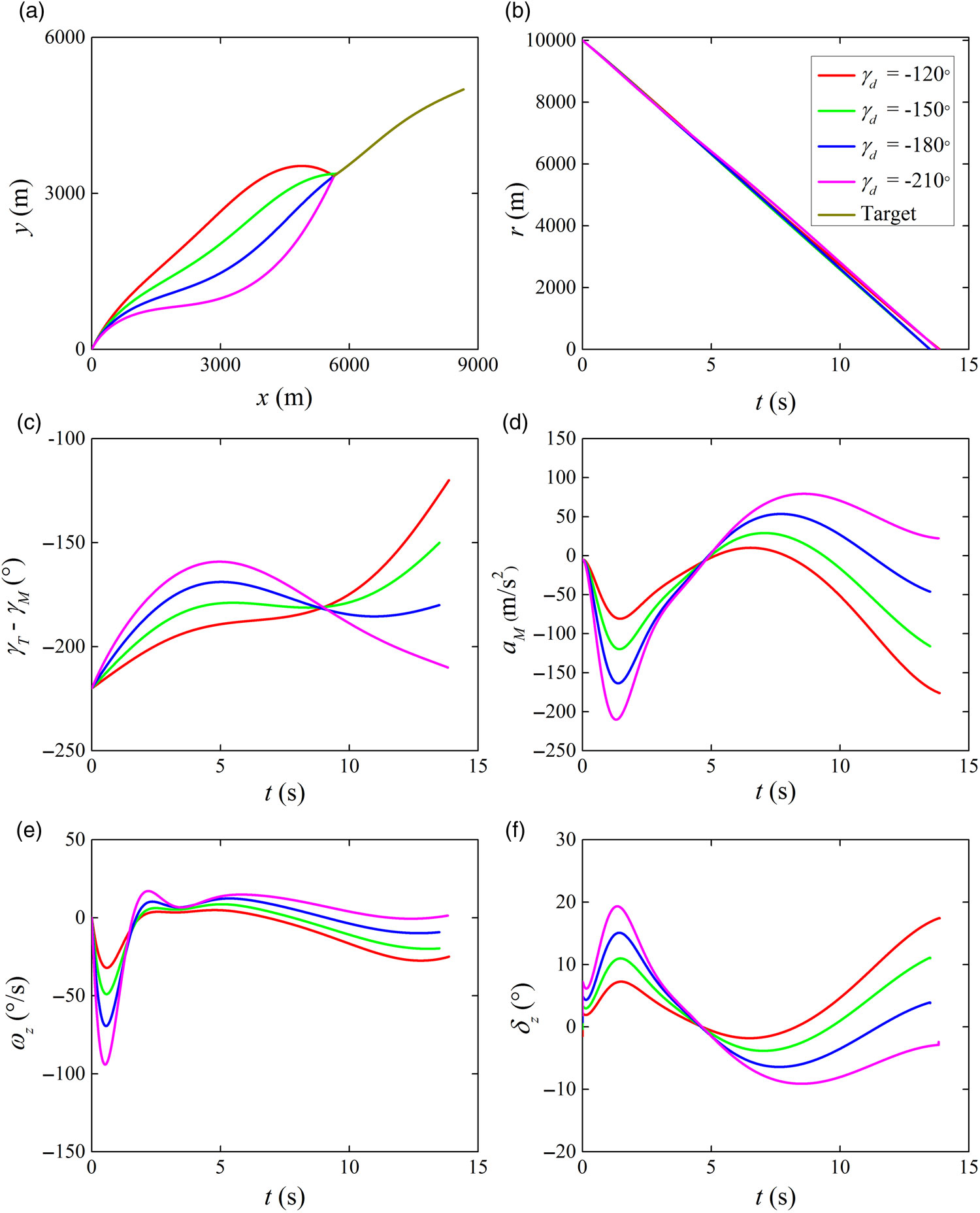
, respectively. The simulation results are shown in Fig. 3. The terminal miss distance and impact angle error are presented in Table 2. It follows from Table 2 and Fig. 3 that small acceptable miss distances and impact angle errors are obtained by the proposed IGC law for impact angle constrained target capture. Specifically, the impact angle error and the miss distance are less than 0.005 Deg and 0.5 m, respectively. Also, it can be seen from Fig. 3 that fin deflection angle command is within the allowable maximum value and quite smooth during the homing engagement. Consequently, hard constraints on the impact angle error and miss distance are both guaranteed by the proposed IGC law against an unknown-manoeuvring target with the limit of actuator resource.
$-210\; {\rm Deg}$
, respectively. The simulation results are shown in Fig. 3. The terminal miss distance and impact angle error are presented in Table 2. It follows from Table 2 and Fig. 3 that small acceptable miss distances and impact angle errors are obtained by the proposed IGC law for impact angle constrained target capture. Specifically, the impact angle error and the miss distance are less than 0.005 Deg and 0.5 m, respectively. Also, it can be seen from Fig. 3 that fin deflection angle command is within the allowable maximum value and quite smooth during the homing engagement. Consequently, hard constraints on the impact angle error and miss distance are both guaranteed by the proposed IGC law against an unknown-manoeuvring target with the limit of actuator resource.
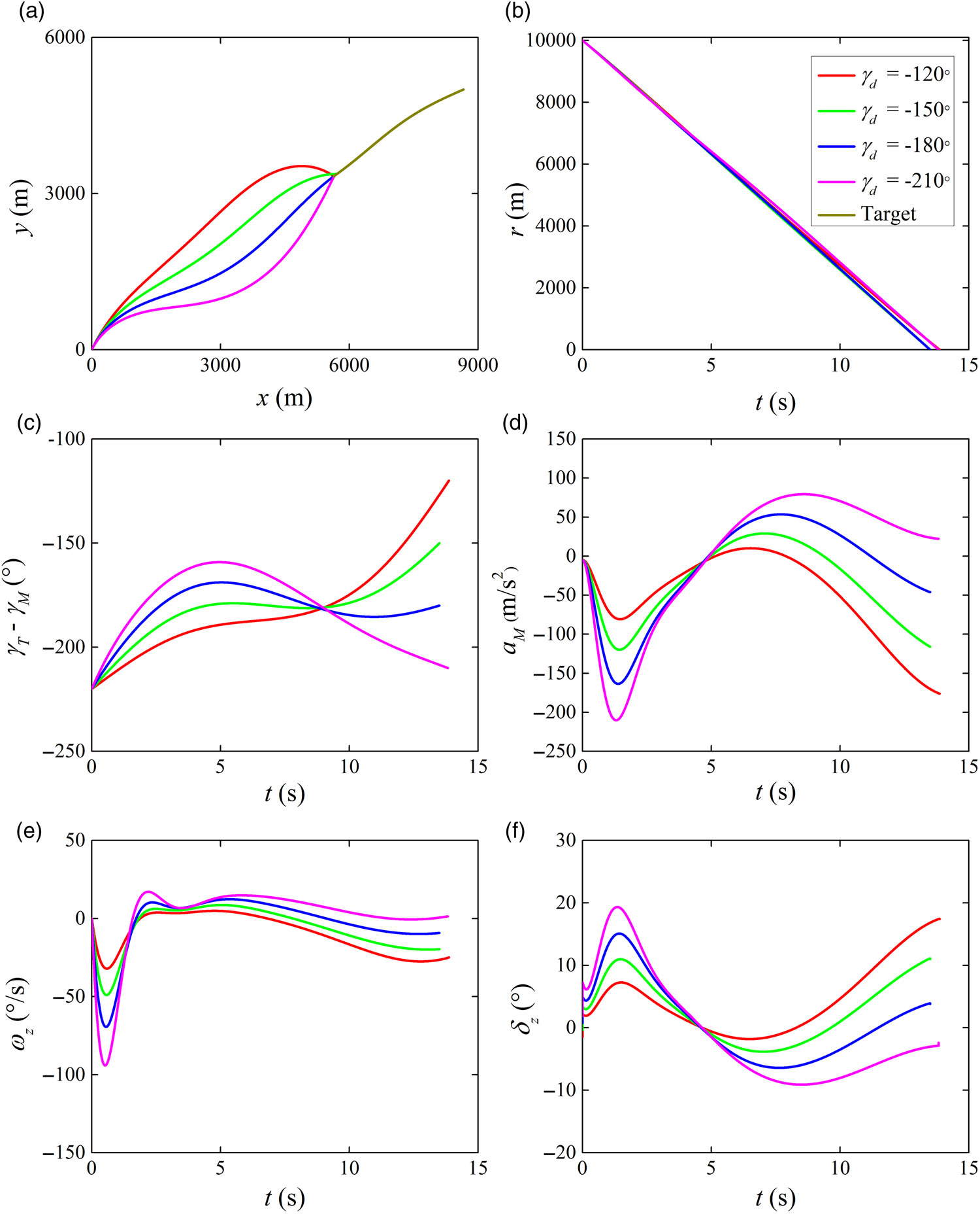
Figure 3. Simulation results with various desired impact angles: (a) interception trajectories, (b) relative distances, (c) LOS angles, (d) missile achieved accelerations, (e) pitch angular rates and (f) fin deflections.
Table 2 Miss distance and impact angle error

4.2 Comparison with the NTSM law
To evaluate the superiority of the proposed IGC law, a comparison simulation with the well-known NTSM law is carried out in this case. The NTSM law is defined as
 $$\matrix{
{s = \left( {\lambda - {\lambda _d}} \right) + \beta {{\left( {\dot \lambda - {{\dot \lambda }_d}} \right)}^\alpha },\;\;\alpha = {p \over q},\;\;p > q} \cr
{{a_M} = {r \over {\cos \left( {{\gamma _M} - \lambda } \right)}}\left( { - {{2\dot r\dot \lambda } \over r} + {1 \over {\alpha \beta }}{{\dot \lambda }^{\left( {2 - \alpha } \right)}}} \right) + {{\varepsilon sgn\left( s \right)} \over {sgn\left( {\cos \left( {{\gamma _M} - \lambda } \right)} \right)}}} \cr
} $$
where
![]() $\beta >0$
and
$\beta >0$
and
![]() $\varepsilon >0$
are design gains; p and q are two positive odd integers, such that
$\varepsilon >0$
are design gains; p and q are two positive odd integers, such that
![]() $1<\alpha <2$
. To improve the performance of the NTSM law, it is assumed that the desired acceleration
$1<\alpha <2$
. To improve the performance of the NTSM law, it is assumed that the desired acceleration
![]() $a_{M} $
generated by the NTSM law can be produced without any autopilot lag. Whereas the proposed IGC law acts on the missile dynamics in Equation (7). The acceleration limit is considered as
$a_{M} $
generated by the NTSM law can be produced without any autopilot lag. Whereas the proposed IGC law acts on the missile dynamics in Equation (7). The acceleration limit is considered as
![]() $\left|a_{M} \right|\le 200\; {\rm m/s}^{{\rm 2}} $
for the NTSM method. The desired impact angle is selected as
$\left|a_{M} \right|\le 200\; {\rm m/s}^{{\rm 2}} $
for the NTSM method. The desired impact angle is selected as
![]() $\gamma _{d} =-160{\rm Deg}$
.
$\gamma _{d} =-160{\rm Deg}$
.
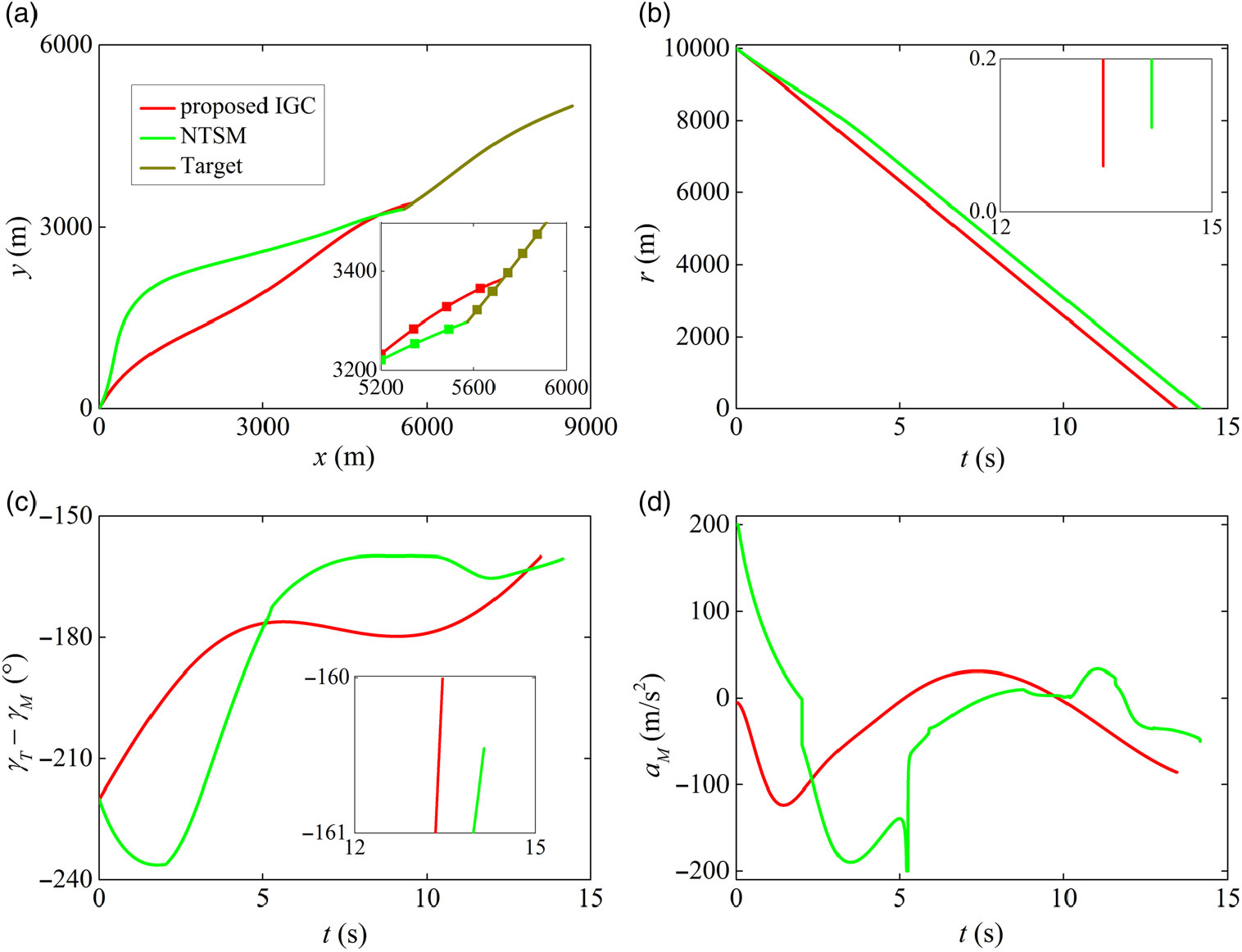
Figure 4 illustrates the simulation results in detail. It can be seen from this figure that both the proposed IGC law and the well-known NTSM approach can successfully navigate the missile to attack the target with desired impact angle; however, the proposed IGC law achieves better accuracy with relatively less acceleration than the NTSM law. Moreover, Equation (38) indicates that the NTSM law requires the acceleration information of the target in sliding surface design, which may not be suitable for practical applications because the future action of the target usually cannot be predicted beforehand. Compared with the NTSM method, the introduction of the adaptive law in the IGC law design contributes to overcome this drawback effectively.
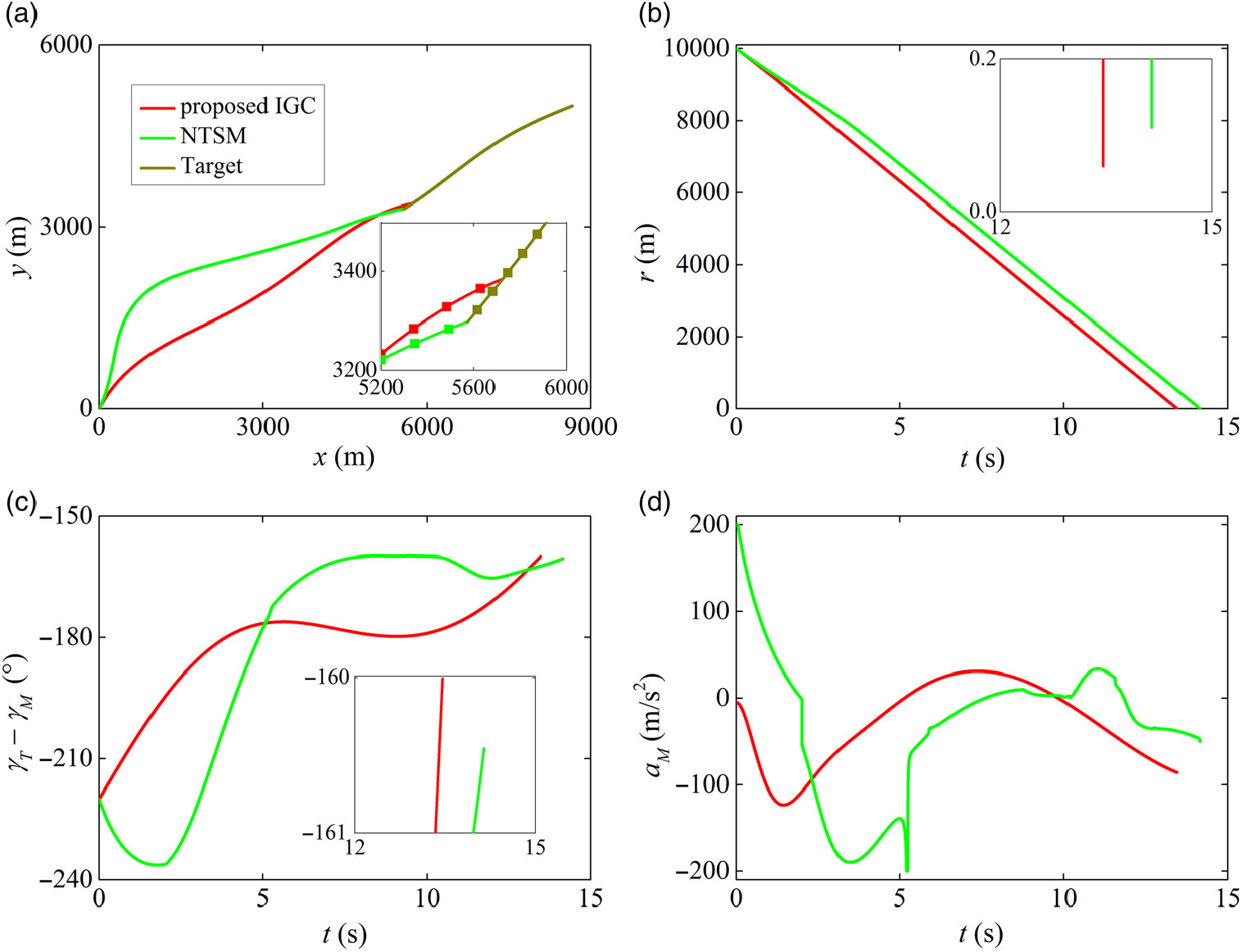
Figure 4. Comparison results with the NTSM law: (a) interception trajectories, (b) relative distances, (c) LOS angles and (d) missile achieved accelerations.
5.0 CONCLUSIONS
This study considers the full impact angle constrained IGC law design problem for manoeuvring target interception with actuator saturation. By regarding the target acceleration and aerodynamic uncertainties as lumped disturbances, an adaptation law is proposed to estimate the upper bound of the disturbances. Based on the adaptation law, the proposed IGC law is preformed via the typical backstepping process, where a fixed-time differentiator is introduced to avoid the problem of ‘explosion of complexity’. Moreover, an auxiliary first-order filter is also presented to cope with the actuator saturation problem. Stability analysis is carried out by selecting a typical Lyapunov function candidate. Simulation results with comparison examples are given to demonstrate the superiority of the proposed integrated guidance and control law.
Supplementry Material
To view supplementary material for this article, please visit https://doi.org/10.1017/aer.2019.71.


